


INC
JAA78151-R.3584.A
AF-S VR Zoom-Nikkor ED 70-200mm f/2.8G IF
REPAIR MANUAL
NIKON CORPORATION
Tokyo, Japan
|
Copyright 2003 by Nikon Corporation. |
Recycled paper |
All Rights Reserved. |
|
|
Printed in Japan February 2003 |
|
INC
JAA78151-R.3584.A
SPECIFICATIONS
Type of lens |
G-typeAF ZoomNikkor lens having built-in CPU and Nikon bayonet mount |
|
|
Focal length |
70mm-200mm |
|
|
Maximum aperture |
f/2.8 |
|
|
Lens construction |
21 elements in 15 groups (5 ED lens elements) |
|
|
Picture angle |
34°20′-12°20′(27°40′-9°50′with IX 240 system cameras, |
|
22°50′-8°with Nikon Digital Camera D1/D1H/D1X/D100) |
|
|
Focal length scale |
70, 80, 105, 135, 200 mm |
|
|
Distance information |
Output to camera body |
|
|
Zoom control |
Manually via separate zoom ring |
|
|
Focusing |
Nikon Internal Focusing (IF) system (utilizing an internal Silent Wave Motor); |
|
manually via separate focus ring |
|
|
Shooting distance scale |
Graduated in meters and feet from 1.5m (5ft.) to infinity (∞) |
|
|
Closest focus distance |
1.5m at all zoom settings :Auto Focus |
|
1.4m at all zoom settings : Manual Focus |
|
|
Diaphragm |
Fully automatic |
|
|
Aperture range |
f/2.8 to f/22 |
|
|
Exposure measurement |
Via full-aperture method with cameras having CPU interface system |
|
|
Attachment size |
77mm (P 0.75mm) |
|
|
Dimensions |
Approx. 87mm dia. ×215mm extension from the camera's lens mount flange |
|
|
Weight |
Approx.1,470g |
|
|
|
|
- M1 AF-S VR 70-200/2.8G -
INC
JAA78151 R.3584.A
BEFORE DISASSEMBLING, DISASSEMBLING AND ADJUSTING
This lens loads the VR (Vibration Reduction) unit to perform the vibration reduction function.
To maintain the accuracy of the vibration reduction function, be sure to perform the VR adjustment by using the VR lens adjustment equipment (J15380) when removing the VR unit and Gyro PCB.
However, the VR adjustment is not necessary when disassembling the other parts.
The optical axis between the 1st lens group and the VR unit has been adjusted so that the optical axis would not dislocate when the 1st group lens injects at zooming operation.
When replacing the 1st lens group or removing the VR unit, it is necessary to adjust the optical axis by using the auto collimator and the special tool.
At the service facilities where [VR lens adjustment equipment] and [ Auto Collimator and Special Tool] are not set up, do not repair or disassemble the product applicable to the above.
INC
JAA78151-R.3584.A
DISASSEMBLING/ASSEMBLING/ADJUSTMENT
DISASSEMBLING
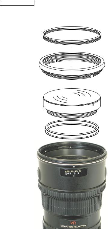
1st LENS GROUP
74
B111
1st lens group
Ref.
#74 is fixed with the frosted black paint190 and B111 is with the Screw Lock.
If the solvent (e.g. ethanol, etc) is poured into the clearance between #74 and B111, it is easier to detach them.
- L1 AF-S VR 70-200/2.8G -
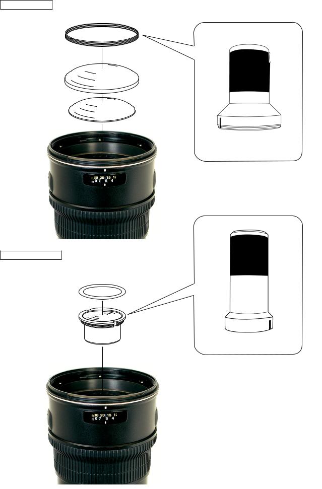
G4 G5 LENS
2nd LENS GROUP
Changed page  ×
×
INC
JAA78151-R.3584.A
47
Addition
J11296
Addition
J11295
●The sheet #202 is attached with the both-sided adhesive tape.
Note:As there is a risk of deformation of the internal mechanism, when detaching the 2nd lens group, take it out where the zoom ring is positioned on the TELE side (200mm) rather than the WIDE one (80mm).
September. 20. 2007
- L AF-S VR 70-200/2.8G -
INC
JAA78151-R.3584.A
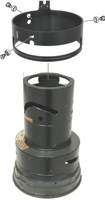
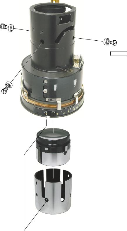
TRIPOD RING
B117
194 × 2
196 × 2
Tripod ring
 155 × 3
  157 × 3
Detach #155 and #157 by turning the tripod socket ring as shown in the above.
Note : There are 3 parts each for #155 and #157.
Detach the tripod socket ring as shown in the left .
- L3 AF-S VR 70-200/2.8G -
INC
JAA78151-R.3584.A
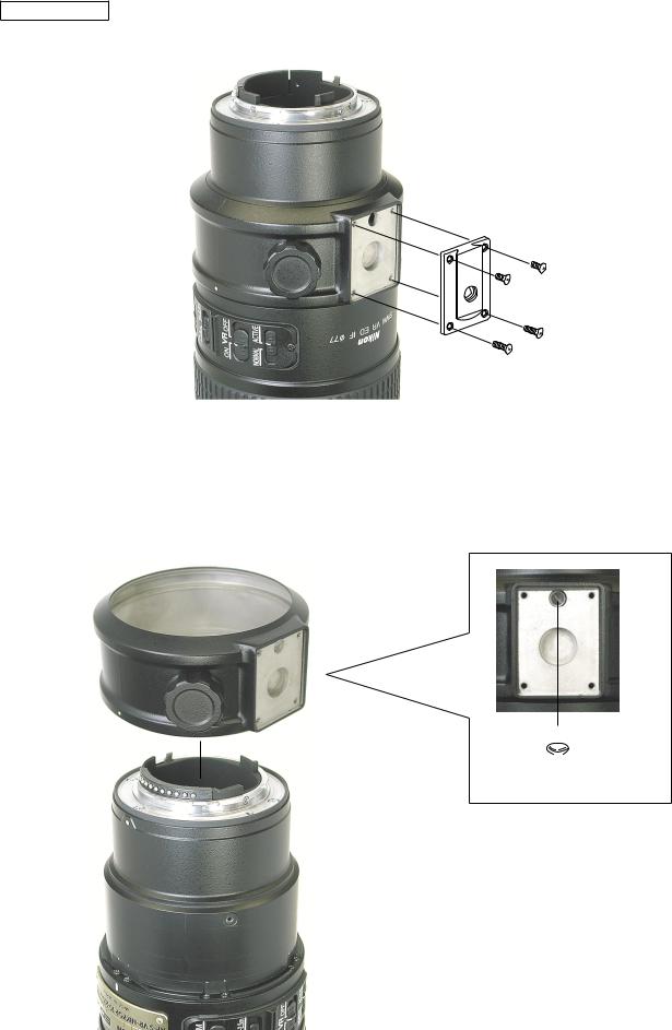
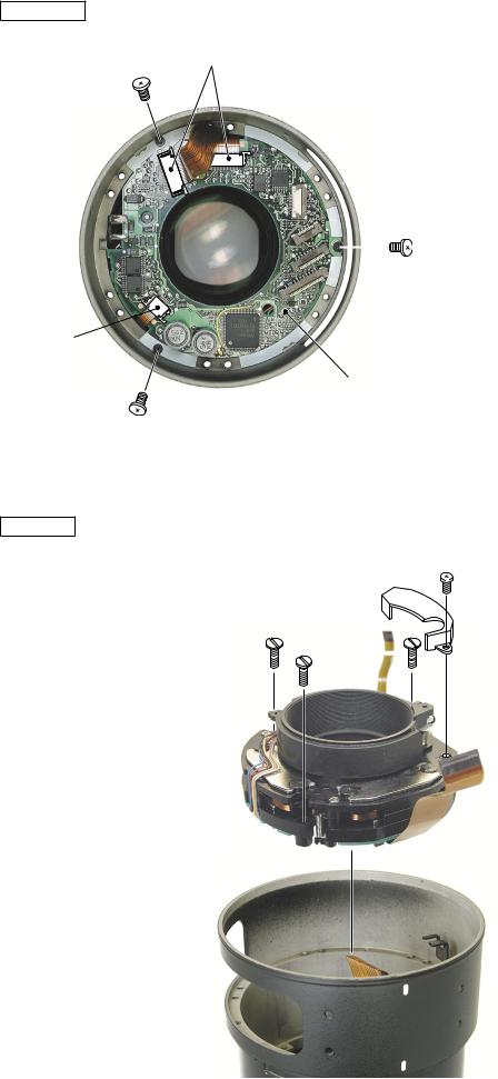
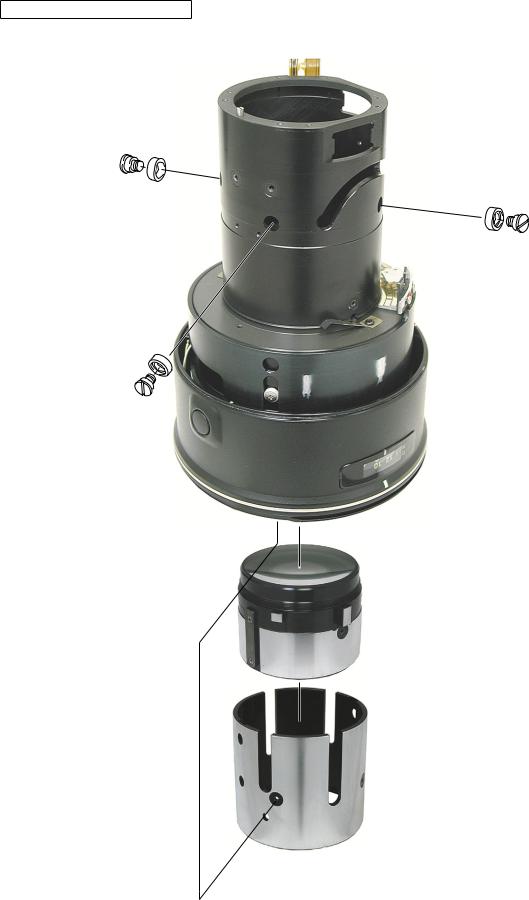
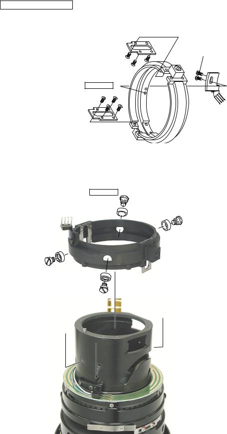
SELECTOR SWITCH UNIT
82 × 2
B107
Connectors
●If the selector switch B107 is lifted and removed, it is seen that the FPCs are connected to the connectors on the main PCB.
Disconnect the FPC that comes from the selector switch and the other 2 FPCs from the 3 connectors.
SEPARATION OF THE REAR GROUP
138 × 11
101
113
99 × 4
- L4 AF-S VR 70-200/2.8G -
INC
MAIN PCB
connector
149 × 3
connector 
Main PCB
VR UNIT
JAA78151-R.3584.A
Detach the FPCs from the 3 connectors.
Remove the 3 screws #149 and detach the main PCB.
351
B108
135 × 3
VR UNIT
- L5 AF-S VR 70-200/2.8G -
INC
JAA78151-R.3584.A
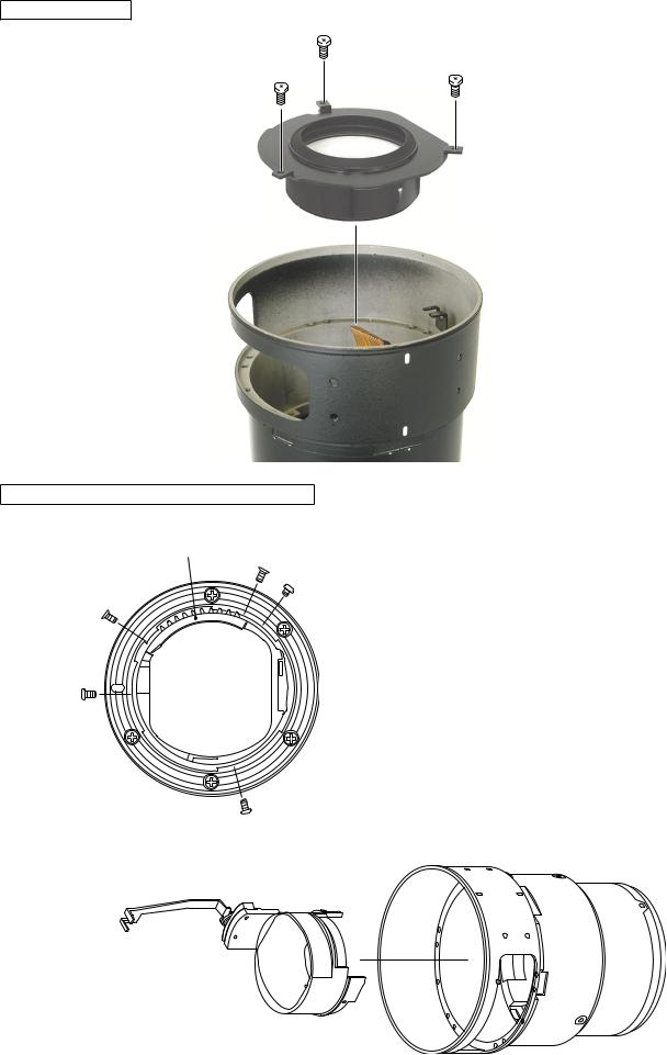
6th LENS GROUP
143 × 3
6th lens group
REAR COVER RING,APERTURE LEVR UNIT
AF Contact
79
191 × 2
● By unscrewing the 2 screws #191, theAF contact part can be detached.
67 × 2
Rear cover ring,Aperture lever unit
- L6 AF-S VR 70-200/2.8G -
INC
JAA78151-R.3584.A
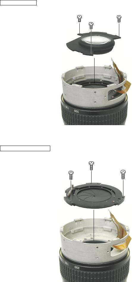
4.th LENS GROUP
142 × 3
4th lens group
APERTURE BLADE UNIT
76 × 3
- L7 AF-S VR 70-200/2.8G -
INC
JAA78151-R.3584.A
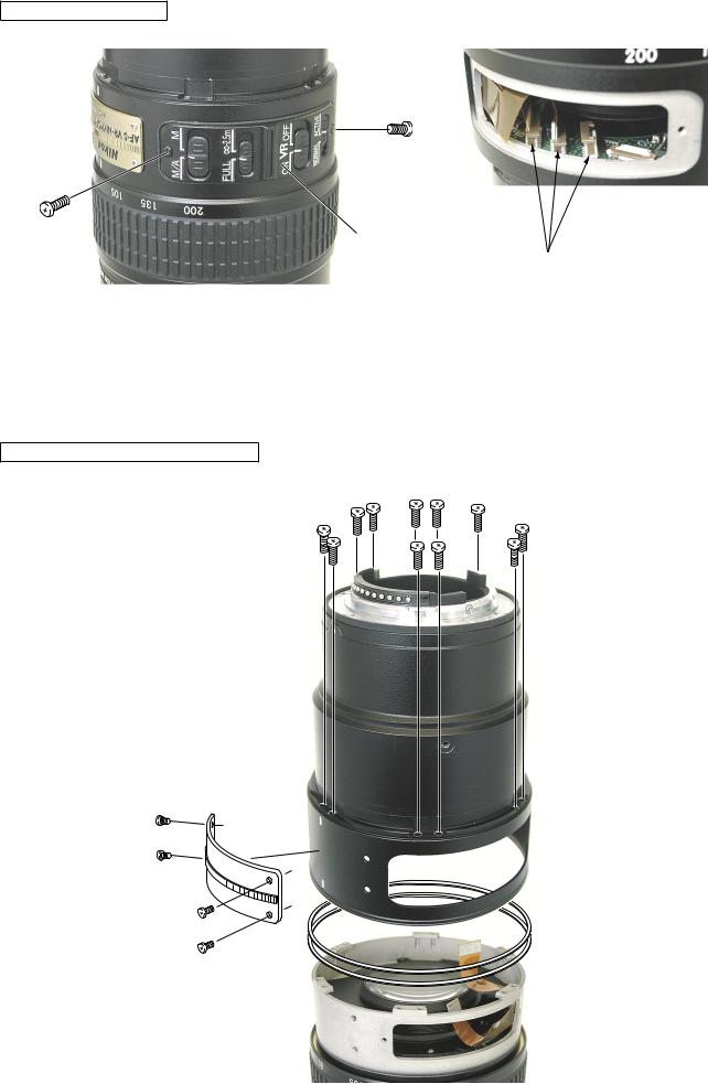
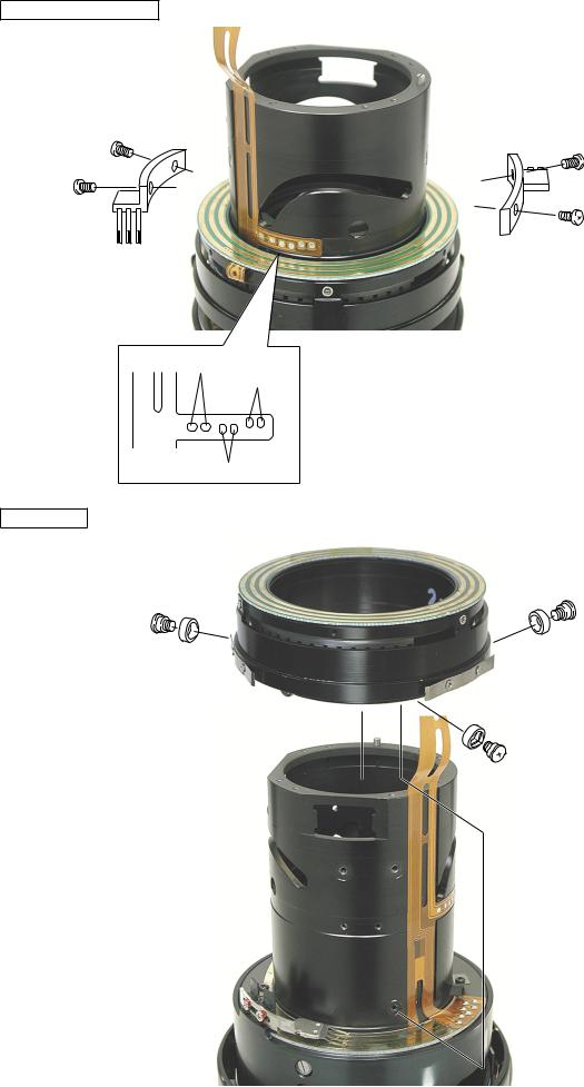
ZOOM RING
35
Tape
Zoom ring
122 × 2
121 × 2
113
176 × 2
- L8 AF-S VR 70-200/2.8G -

INC
JAA78151-R.3584.A
ZOOM FIXED RING, MF RING
86 × 8
Zoom fixed ring
113
MF ring
- L9 AF-S VR 70-200/2.8G -

INC
JAA78151-R.3584.A
ZOOM MIDDLE RING
136 × 2 |
130 × 2 |
|
127 × 2
131 × 2
170 × 2
154 × 4
 155 × 4
Zoom middle ring
- L10 AF-S VR 70-200/2.8G -
INC
JAA78151-R.3584.A
POWER BRUSH UNIT
133 × 4
Black
Blue
White
SWM UNIT
Note : Remove the solder completely from the wire-soldering pattern that is shown in the left.
SWM unit
172 × 3
173 × 3
- L11 AF-S VR 70-200/2.8G -
INC
JAA78151-R.3584.A
CAM RING, 3rd LENS GROUP
152 × 3
151 × 3
- L12 AF-S VR 70-200/2.8G -

INC
JAA78151-R.3584.A
FOCUS LOCK RING UNIT
137 × 6
Focus Lock Ring Unit
DISTANCE ENCODER BRUSH, FOCUS INDEX UNIT
B10
146 × 2
216
218 × 2
B66
96 × 2
- L13 AF-S VR 70-200/2.8G -
INC
JAA78151-R.3584.A
MR HEAD, BRUSH UNIT,AF-L FPC
Solder Bridge |
|
|
● Remove the solding bridges and the solder for each wire. |
||
|
|
|
|
|
|
|
|
|
|
|
|
|
White Brush unit |
White AF-L FPC |
Yellow Brush unit |
Green AF-L FPC |
|
112
B89
MR head
96 × 2
B65
140 × 3
- L14 AF-S VR 70-200/2.8G -

INC
JAA78151-R.3584.A
G4 G5 LENS HOUSING
24
179 × 2
 180 × 2170 × 3
125 |
134 |
|
|
136 126 |
|
FOCUS MIDDLE RING
 129 × 2
128 × 2
- L15 AF-S VR 70-200/2.8G -
INC
JAA78151-R.3584.A
128 × 3
129 × 3
B61
- L16 AF-S VR 70-200/2.8G -
INC
JAA78151-R.3584.A
ASSEMBLING/ADJUSTMENT
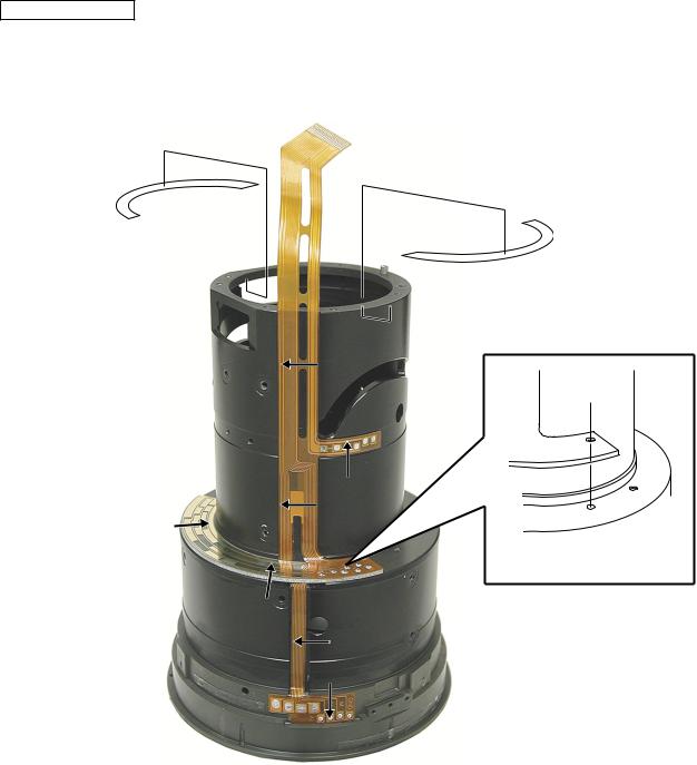
RELAY FPC UNIT
B59
227 × 2
(Align the positions of the holes.)
● As shown in the above, attach the B59 by moving towards the direction of arrow for each position.
- L17 AF-S VR 70-200/2.8G -
INC
JAA78151-R.3584.A
FOCUS MIDDLE RING
Lock End B
128 × 3
129 × 3
B61
I-40
 129 × 2
128 × 2
Lock End B
- L18 AF-S VR 70-200/2.8G -

INC
JAA78151-R.3584.A
G4 G5 LENS HOUSING
24
I-40
Lock End B
179 × 2
 180 × 2170 × 3
125 |
134 |
|
126
Lock End B
AF-L FPC
B65
140 × 3
Lock End B
- L19 AF-S VR 70-200/2.8G -

INC
JAA78151-R.3584.A
MR HEAD, BRUSH UNIT
Screw Lock
112
B89
MR head
96 × 2
Solder bridge
● Solder the soldering bridges and each wire.
|
White Brush unit |
White AF-L FPC |
Yellow Brush unit |
Green AF-L FPC |
|
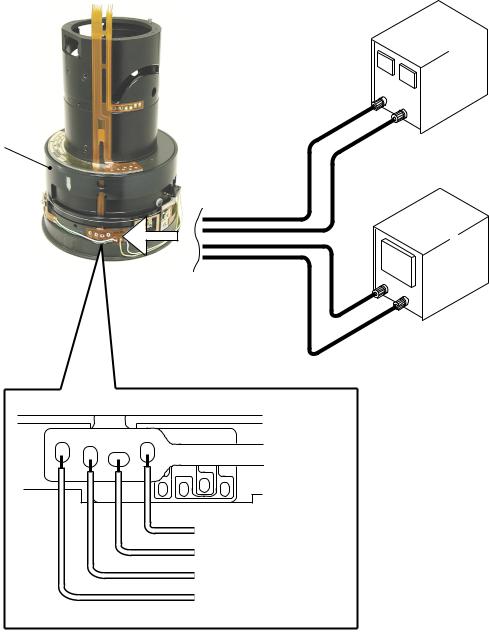
INSPECTIONANDADJUSTMENT FOR THE WAVEFORM OUTPUT FROM MR ENCODER
● In case of disassembling or replacing the MR head, be sure to conduct adjustment.
Equipment and tools to be required
Single output rated voltage power supply: 1 unit With 5.0V and 100mA, applicable to the self-made toolOscilloscope: 1 unit
Self-made tool: 1 unit
Prepare the measuring lens
Solder the lead wire on the soldering bridge that attatches the MR head and connect with each measuring instrument.ref. the next page
- L20 AF-S VR 70-200/2.8G -
INC
JAA78151-R.3584.A
Connection diagram
Power supply
 Set values
.
B61
Oscilloscope
2ch
Oscilloscope (2ch)
Power supply (+)
Oscilloscope (1ch)
Power supply (GND)
- L21 AF-S VR 70-200/2.8G -
INC
JAA78151-R.3584.A
How to conduct inspection and adjustment
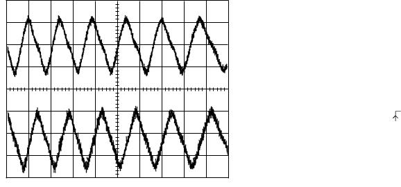
Make sure that the current and voltage of the connected rated voltage power supply are set values.If they meet the set values, turn on the power.
Set the oscilloscope and drive the focus ring by hand.
Note Since the shape of waveform varies according to the driving speed of B61, particularly and properly set Time/Div.
In case of detecting any wider waveform noise, use the filter function.
How to set the filer function in the employment case of Yokogawa-manufactured DL1540
Press the filter button.
Select "Smooth" in the menu on the PC screen.
CH1=20mV |
CH2=20mV |
5ms/div |
AC 10:1 |
AC 10:1 |
|
|
|
NORM 200KS/s |
● Setting of oscilloscope
V/Div CH1 |
|
V/Div CH2 |
|
Coupling |
|
Time/Div |
m Sec |
Trigger Mode |
NORMAL |
Trigger Coupling |
|
Trigger Source |
|
Trigger Position |
div |
Trigger Type |
EDGE |
Trigger Level |
|
Standard The amplitude of every pulse/waveform should be 50mV or more.
Note Check the waveform by letting the B61 to travel from the infinity-end position to the near distance end position and vice versa.
- L22 AF-S VR 70-200/2.8G -
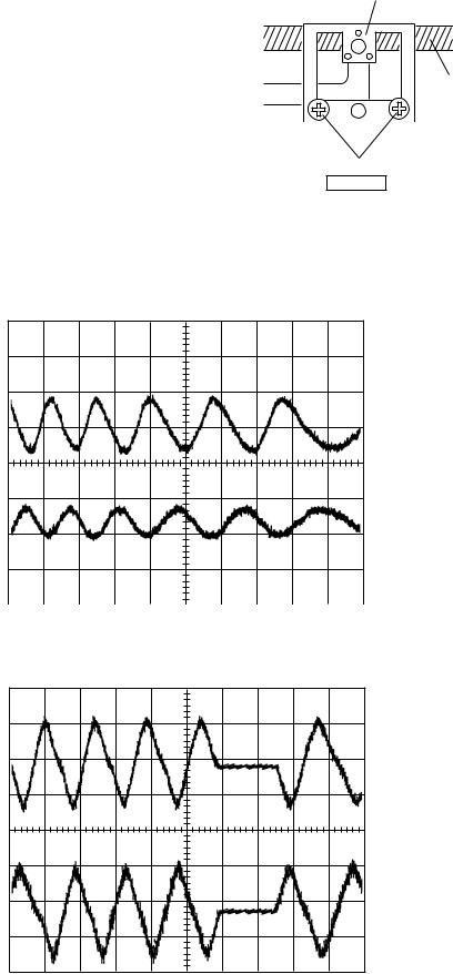
In the case of smaller amplitude, for adjustment, loosen
the two screws #96 and then shift the MR head position
as shown in the right figure.
Note During adjustment, prevent the magnetic tape and MRhead from touching the magnetized driver bit, or the magneticdata may be damaged.
INC
JAA78151-R.3584.A
MR head
Magnetic tape
96 × 2
Screw lock
Reference
● In case the amplitude of either CH1 or CH2 seems smaller, one of the two screws #96 may be loosened.
Then, check the screws. In case the screws are fully tightened, the MR head may be troubled. Then, be sure to
replace the MR head unit B88 and adjust it again.
CH1=20mV |
CH2=20mV |
5ms/div |
AC 10:1 |
AC 10:1 |
|
|
|
NORM 200KS/s |
● In case there is a drop partially in the amplitude of vibration between the infinity and the closest, replace the magnetictape (attached to B61) and readjust it because the data on magnetic tape may be damaged.
CH1=20mV |
CH2=20mV |
5ms/div |
AC 10:1 |
AC 10:1 |
|
|
|
NORM 200KS/s |
Turn the power supply OFF.
- L23 AF-S VR 70-200/2.8G -
INC
JAA78151-R.3584.A
DISTANCE ENCODER BRUSH, FOCUS INDEX UNIT
Apply a quick-dry adhesive
B10
146 × 2
216
218 × 2
Lock End B
B66
96 × 2
Screw temporarily the 2 screws each for #146 and # 96.
3rd LENS GROUP
lead key
 ● Apply I-40 grease to the 2 parts of the B77 lead key, and lead key B77 to the 4 parts of the U groove and the entire periphery of
#48.
48
- L24 AF-S VR 70-200/2.8G -
INC
JAA78151-R.3584.A
152 × 3
151 × 3
Lock End B
- L25 AF-S VR 70-200/2.8G -

INC
JAA78151-R.3584.A
SWM UNIT
SWM unit
Lock End B
POWER BRUSH UNIT
Screw Lock
133 × 4
Black
Blue
White
- L26 AF-S VR 70-200/2.8G -
INC
JAA78151-R.3584.A
ZOOM MIDDLE RING
139 × 2
141 × 2
B11
Lock End B
144 × 8
37
Lock End B
154 × 4
 155 × 4
37
● Apply the G92KA on the inside ofthe zoom middle ring #37.
- L27 AF-S VR 70-200/2.8G -
 Loading...