


INC
JAA80251-R.3723.A
AF-S Zoom-Nikkor ED
24-70mm/F2.8G(IF)
JAA80251
REPAIR MANUAL
Copyright 2007 by Nikon Corporation. All Rights Reserved.
!!
Printed in Japan November 2007

INC
JAA80251-R.3723.A
Before Disassembly / Reassembly / Adjustment
When disassembling/(re)assembling, be sure to use the conductive mat (J5033) and wrist strap (J5033-5) for static protection of electrical parts.
When disassembling, make sure to memorize the processing state of wires, screws to be fixed and their types, etc.
When FPCs are connected to PCBs, etc, put the FPCs in connectors, etc, straightforward so that they are all the way seated.
Because prototypes are used for "Disassembly/(Re)assembly/Adjustment", they may differ from the actual products in forms, etc.
Because pictures are processed by a special method, they may differ from the actual ones in texture.
This lens will need the optical lens-alignment work in case of performing the below work. Therefore, after the work, adjust optical lens-alignment at service facilities where such work can be carried out.
Disassembly of 1-1 lens group unit, 4th lens group unit
Replacement of 1-1 lens group unit, 1-2 lens group unit, 3rd lens group unit, 4th lens group unit, 1st lens-G lead ring, helicoid tube unit
Points to notice for Lead-free solder products
Lead-free solder is used for this product.
For soldering work, the special solder and soldering iron are required.
Do NOT mix up lead-free solder with traditional solder.
Use the special soldering iron respectively for lead-free solder and lead solder.
They cannot be used in common.
- AF-S 24-70/2.8G -
INC
JAA80251-R.3723.A
1. Disassembly
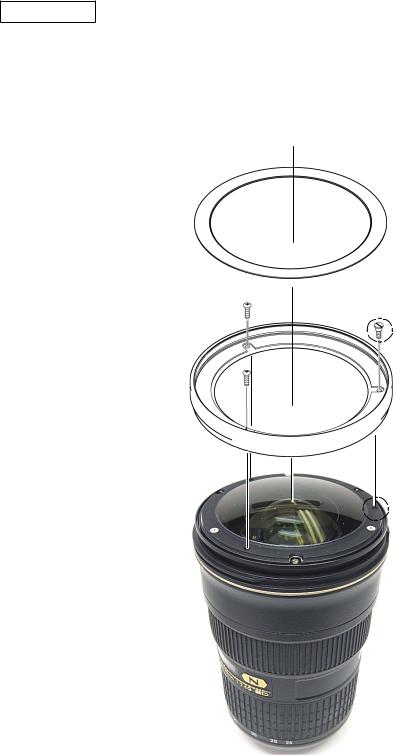
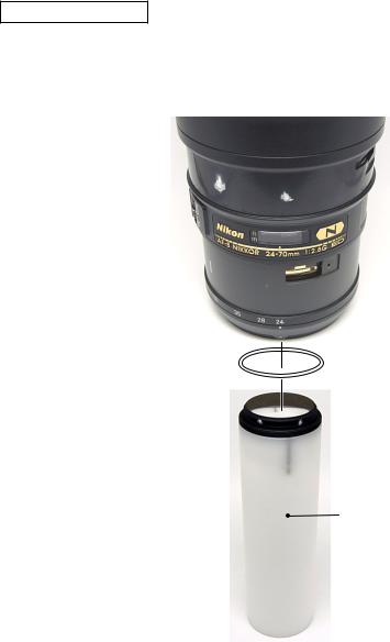
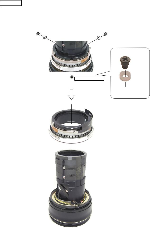
Filter ring
Remove the sheet.
Take out the two screws (#63) and the screw (#79), and remove the filter ring.
Sheet
#63×2
#79 Shoulder screw
Filter ring
- AF-S 24-70/2.8G -
INC
JAA80251-R.3723.A
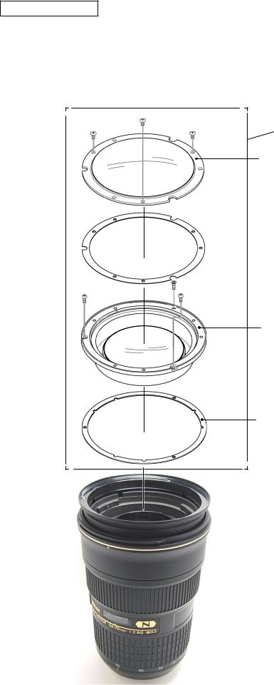
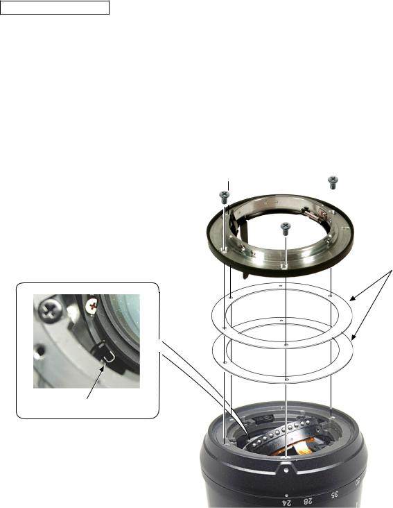
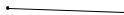
1st lens-G unit
Take out the two screws (#50) and the screw (#61), and remove the 1st lens-G unit.
Caution: If the G1 lens is removed, the lens alignment work will be necessary.
#72×3
1st lens group
G1 lens
#76
#61 (Countersunk screw)
#50×2
G2, G3 lens
#77
Adjustment washer (A-I)
- AF-S 24-70/2.8G -
INC
JAA80251-R.3723.A
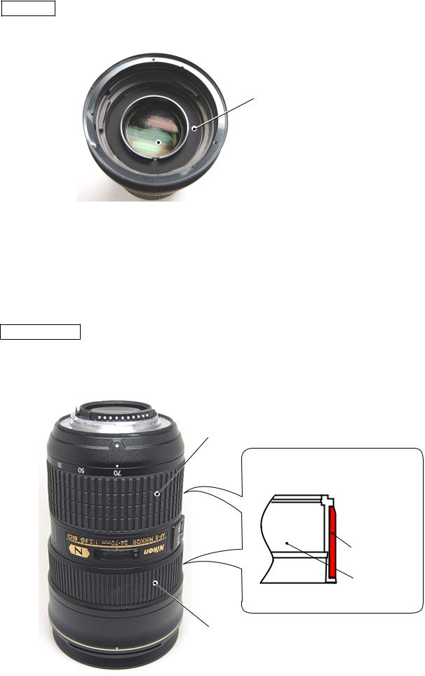
Sheet
Remove the sheet (#163).
#163
 G4 lens
G4 lens is the hybrid aspheric lens.
R1-surface of G4 lens is plastic surface, so dip a wiping cloth (Savina Minimax) a little in ethanol, and wipe the surface lightly. If dust/dirt is attached, blow them away with a blower as much as possible.
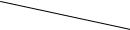
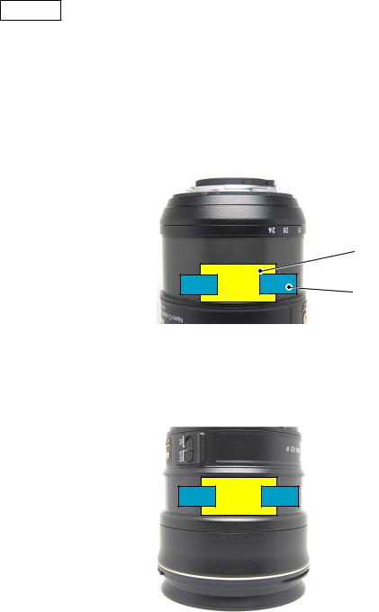
Rubber ring
Remove the zoom rubber ring.
Remove the focus rubber ring.
Zoom rubber ring
Bayonet side
 Sloped
Rubber ring
Zoom ring
Cross-section view of Focus ring/Zoom ring
Focus rubber ring
- AF-S 24-70/2.8G -
INC
JAA80251-R.3723.A
Tape
Peel off the four pieces of the tape (#193) of - , and remove the two cover plates (#194).
Zoom brush
#194
#193 |
M/A brush
- AF-S 24-70/2.8G -

INC
JAA80251-R.3723.A
5th lens Group
Take out the three screws (#182) of the 5th lens group.
Take out the two screws (#180) of the contacts unit.
Caution: For [#182], a thicker screw (1K010-343) may be used to fit with the larger screw hole caused by adjustments. So check the screw diameter. [#182] has M1.4-diameter, while [1K010-343] has M1.7-diameter. 
5th lens group
 #182×3
Thicker screws may be used.
 #180×2
Zoom brush
Take out the screw (#96), and remove the zoom brush.
Zoom brush
#96
M/A brush
Take out the screw (#100), and remove the M/A brush.
M/A brush
#100
- AF-S 24-70/2.8G -
INC
JAA80251-R.3723.A
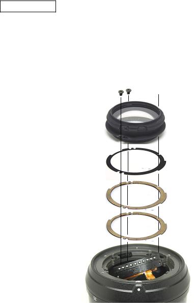
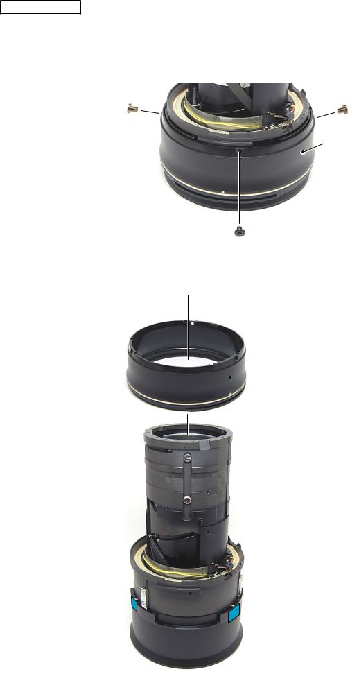
Bayonet mount unit
Take out the four screws (#172).
Remove the bayonet mount unit.
Remove the Bf adjustment washer (#78).
Caution: Handle the blade actuating plate spring with care, because it can be easily deformed.
 #172×4
 Bayonet mount unit
#78
Blade actuating plate spring
- AF-S 24-70/2.8G -
INC
JAA80251-R.3723.A
4th lens group
Remove the 4th lens group.
Caution: Removing the 4th lens group needs the lens alignment work.
 #81×3
#81×3
4th lens group
Washer
Washer
Washer
with being light-shielding tape attached
The hybrid aspheric lens is used for the bayonet side of the 4th lens group. If dust/dirt is attached, blow them away with a blower as much as possible.
If such dust/dirt can not be removed, dip a wiping cloth (Savina Minimax) a little in ethanol, and wipe the surface lightly.
- AF-S 24-70/2.8G -
INC
JAA80251-R.3723.A
3rd lens group
Remove the 3rd lens group with [J11346].
Washer
 3rd lens group
J11346
- AF-S 24-70/2.8G -
INC
JAA80251-R.3723.A
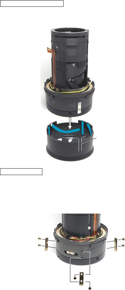
Rear fixed tube
Take out the five screws (#174), and remove the rear fixed tube.
 #174×5
Rear fixed tube
Set the cam tube to WIDE-end. Take out the two screws (#67) and remove the zoom coupling key.
#67×2
Zoom coupling key
- 10 AF-S 24-70/2.8G -
INC
JAA80251-R.3723.A
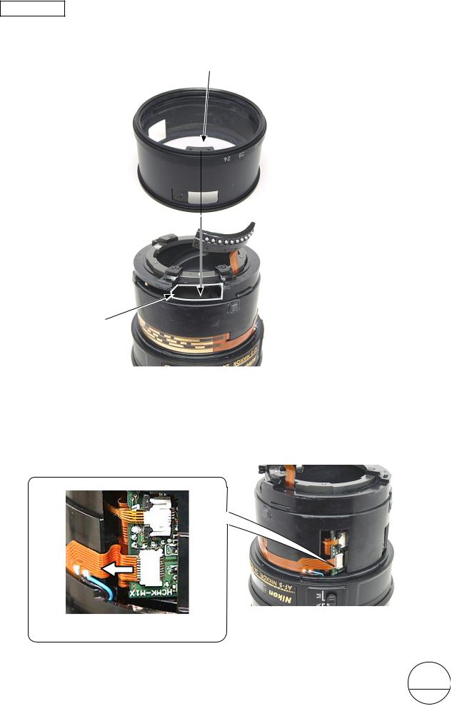
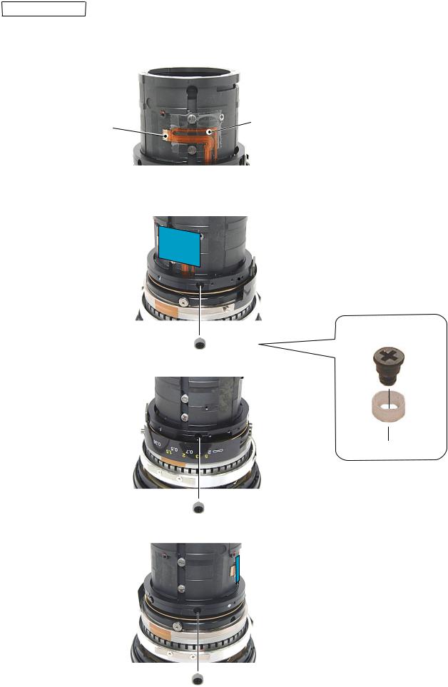
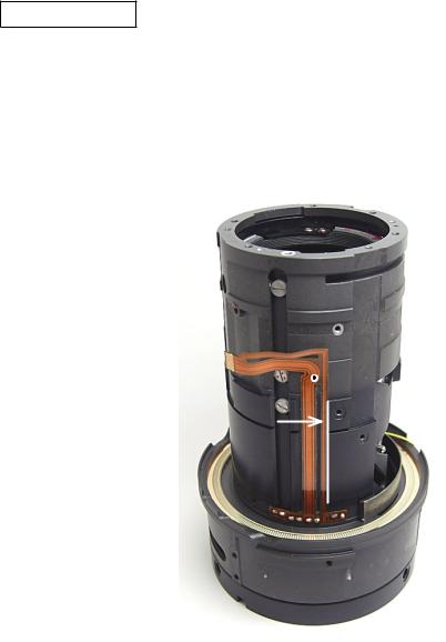
Zoom ring
Align the cutout section of the exterior fixed tube with the convex portion of the zoom ring. Then detach the zoom ring.
Convex portion
Zoom ring
Exterior fixed tube
Cutout section
(Revision)
Disconnect the focus zoom-FPC from the connector of the main PCB.
FocusZoom-FPC
(Revision)
Changed Page × 2 |
- 11 AF-S 24-70/2.8G - |
December.15.2007 |
INC
JAA80251-R.3723.A
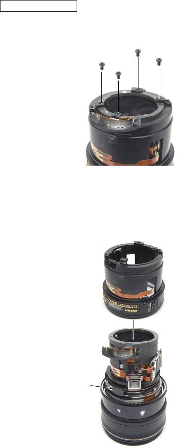
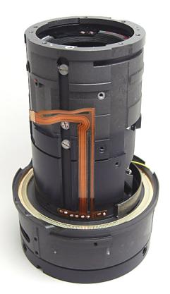
Exterior fixed tube
Take out the four screws (#174) of the exterior fixed tube.
#174×4
Remove the exterior fixed tube.
Caution:When the exteriorfixed tube is removed, be careful not to touch the main PCB and the focus index sheet.
Exterior fixed tube
 Main PCB
Focus index sheet
- 12 AF-S 24-70/2.8G -
INC
JAA80251-R.3723.A
MF ring
Detach the MF ring and washer (#169) from the SWM unit.
#169
MF ring
 SWM unit
- 13 AF-S 24-70/2.8G -

INC
JAA80251-R.3723.A
GMR unit
Peel off the tape (#196).
#196
Disconnect the GMR-FPC from the connector of the main PCB.
Slide the connector in the direction of the arrow, and remove the FPC.
Main PCB
Take out the screw (#73) and remove the GMR unit.
Back
GMR unit |
|
|
|
|
|
Caution |
|
|
|
|
|
|
|
|
NEVER touch the sensor area |
|
|
|
directly by hand. |
|
#73 |
||
|
|
|
|
|
- 14 AF-S 24-70/2.8G - |
||
|
|
||

INC
JAA80251-R.3723.A
Main PCB unit
Take out the screw (#120).
#120
Remove the contact-FPC from the main PCB.
Remove the focus-FPC from the main PCB.
Remove the SWM relay-FPC from the main PCB.
SWM relay-FPC
Contact-FPC
Focus-FPC
Main PCB
Take out the two screws (#81) and two washers (#74), and remove the main PCB unit.
#74×2
#81×2
- 15 AF-S 24-70/2.8G -
INC
JAA80251-R.3723.A
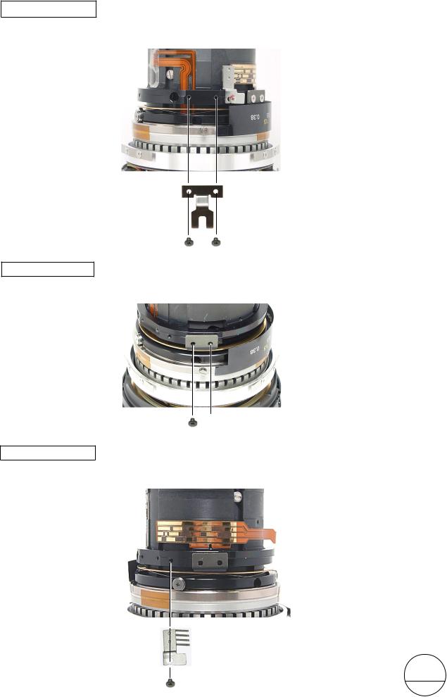
SWM coupling key
Take out the two screws (#96) and remove the SWM coupling key.
SWM coupling key
#96×2
Focus coupling key
(Deletion)
Take out the two screws (#96), and remove the focus coupling key.
 Focus coupling key
 #96×2
#96×2
Focus encoder brush
Take out the screw (#96) and remove the focus encoder brush.
Focus encoder brush
|
|
|
#96 |
|
|
|
||
|
Changed page × 1 |
- 16 AF-S 24-70/2.8G - |
January.10.2008 |
INC
JAA80251-R.3723.A
Focus fixed tube
Attach the protection tape to the SWM relay-FPC. (Do NOT attach the FPC-contacts area.)
SWM relay-FPC |
|
Protection tape |
|
||
|
|
|
|
|
|
Remove the rollers from the focus fixed tube (by following the order from "Fig.1" to "Fig.3".
 Focus fixed tube
|
Roller |
Fig.1 |
#158 |
|
#157 |
Fig.2
Fig.3
- 17 AF-S 24-70/2.8G -
INC
JAA80251-R.3723.A
Focus fixed tube (continued)
Remove the focus fixed tube from the inner fixed tube.
Be careful so that fingers or a screwdriver do NOT touch the magnetic surface.
Magnetic tape
Focus fixed tube
Inner fixed tube
- 18 AF-S 24-70/2.8G -
INC
JAA80251-R.3723.A
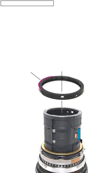
Focus coupling key
Set the zoom to TELE-end position, and disengage the focus coupling key from the focus coupling pin.
Focus coupling key
Lens (front)
Focus coupling pin
∞ infinity-end)
Zoom: TELE-end position
- 19 AF-S 24-70/2.8G -
INC
JAA80251-R.3723.A
Removal of Washer
With alcohol, remove each screw lock that was applied to the washers (#160) at three places.
Push down the washer (#160) at the position of the concave portion of the inner fixed tube, and turn the washer rightwards. (Fig.1 )
Align the convex portion of the washer with the grooved guide track (indicated by white dot lines), then remove the washer (#160) by pushing upwards. (Fig.1 )
Remove the washers (#156 and #161).
Convex portion of Washer
#156
As a result of adjustments, [#156] is not used in some cases.
#161
Inner fixed tube
 Grooved guide track
 Protection tape
Procedure for removing washer
Concave portion of Inner fixed tube

Convex portion of Washer
Fig.1
- 20 AF-S 24-70/2.8G -
INC
JAA80251-R.3723.A
SWM unit
Remove the three rollers of the SWM unit.
Remove the SWM unit from the inner fixed tube.
#158
Roller ×3 |
#159 |
Adhesive: Lockend
Be careful of the facing direction of #159 when assembled.
SWM unit
Inner fixed tube
- 21 AF-S 24-70/2.8G -
INC
JAA80251-R.3723.A
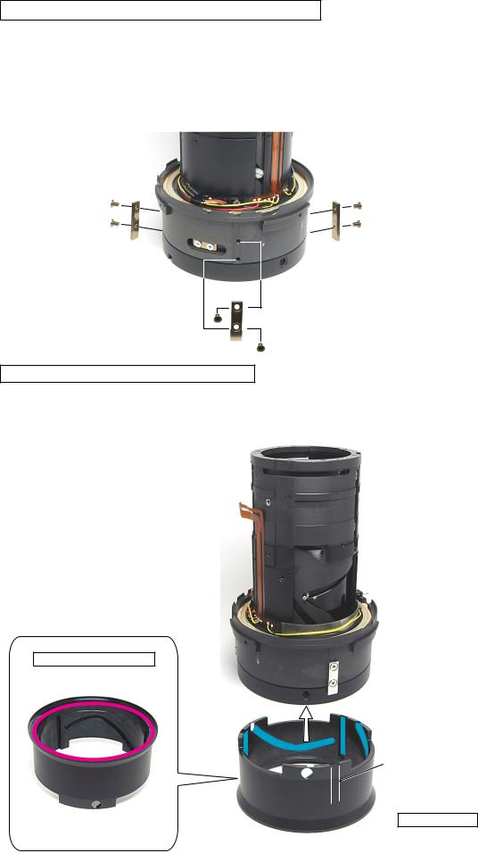
Hood fixed ring
Take out the three screws (#174).
Hood fixed ring
#174×3
Set the zoom to WIDE-end position, and remove the hood fixed ring from the inner fixed tube.
 Hood fixed ring
Inner fixed tube
- 22 AF-S 24-70/2.8G -

INC
JAA80251-R.3723.A
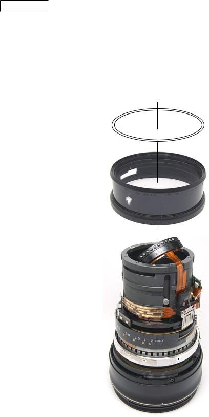
1st lens-G lead ring
Peel off the three pieces of tape (#107).
 #107×3
Remove the three rollers.
Roller ×3
#80
#87
- 23 AF-S 24-70/2.8G -
INC
JAA80251-R.3723.A
1st lens-G lead ring (continued)
Detach the 1st lens-G lead ring by disengaging the three 1st lens-G lead keys from the key grooves.
 1st lens-G lead key
Key groove
1st lens-G lead ring
1st lens-G lead key
Take out the two screws (#191) each at three places, and remove the three 1st lens-G lead keys.
1st lens-G lead key×3
#191×6
- 24 AF-S 24-70/2.8G -
INC
JAA80251-R.3723.A
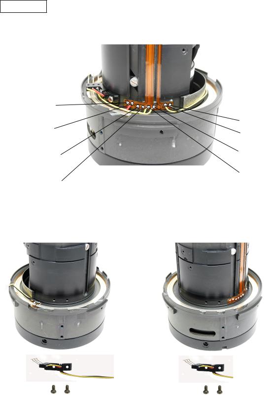
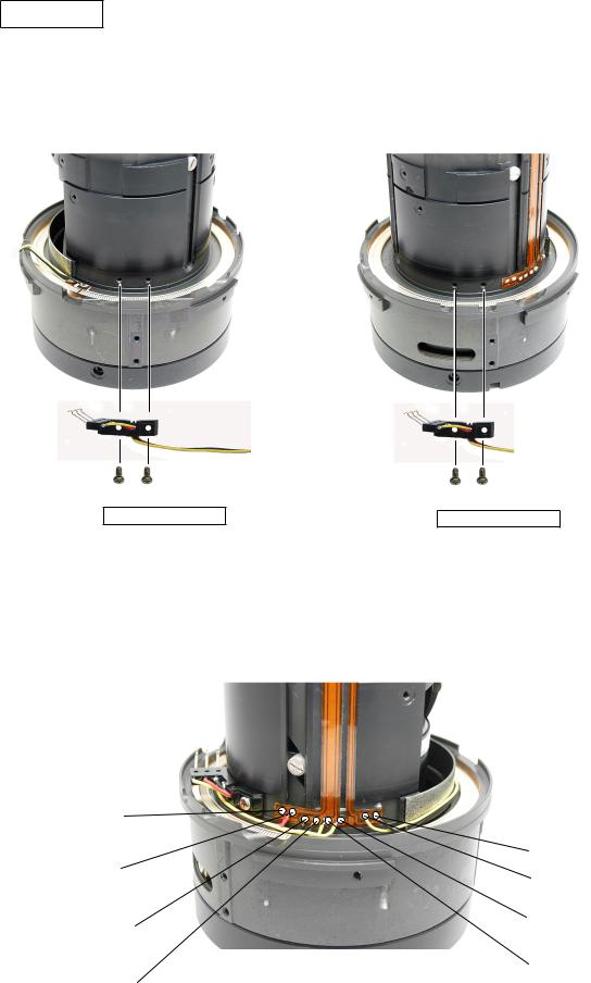
SWM brush
Remove the solders of the eight lead wires (which are connected from the followings) from the SWM relay-FPC.
Red: SWM brush |
Black: M-ring detection |
|
Lead wire/short) |
||
PCB |
||
|
||
Red: SWM brush |
Yellow: M-ring detection |
|
Lead wire/long) |
||
PCB |
Yellow: SWM brush Black: SWM brush (Lead wire/long) (Lead wire/short)
Yellow: SWM brush Black: SWM brush (Lead wire/short) (Lead wire/long)
Take out the two screws (#50) each at two places from the SWM brushes (lead wires/long and short).
|
|
|
SWM brush |
|
|
SWM brush |
|
|
|
|
|||
|
|
|
(Lead wire/long) |
|
|
(Lead wire/short) |
|
|
|
|
|
|
|
#50×2 |
|
|
#50×2 |
|
||
- 25 AF-S 24-70/2.8G -
INC
JAA80251-R.3723.A
Caution:
In order to maintain optical accuracy, the inner fixed tube (1C999-528) is set as assembled unit.
If disassembled, therefore, it will be unrepairable at repair service facilities.
Inner fixed tube (1C999-528)
- 26 AF-S 24-70/2.8G -
INC
JAA80251-R.3723.A
2 Assembly / Adjustment
SWM relay-FPC
Attach the SWM relay-FPC to the inner fixed tube, based on the reference position.
Inner fixed tube
 SWM relay-FPC

 Reference position for attachment
- AF-S 24-70/2.8G -
INC
JAA80251-R.3723.A
SWM brush
Attach the SWM brushes (lead wires/long and short) to the inner fixed tube, and tighten two screws (#50) each at two places.
Inner fixed tube
SWM brush (Lead wire/long)
#50×2
Adhesive: Screw lock
Solder the eight lead wires on the SWM relay-FPC.
Red: SWM brushLead wire/short)
Red: SWM brushLead wire/long)
Black: SWM brush (Lead wire/short)
Black: SWM brush (Lead wire/long)
SWM brush (Lead wire/short)
#50×2
Adhesive: Screw lock
Black: M-ring detection PCB
Yellow: M-ring detection PCB
Yellow: SWM brushLead wire/long)
Yellow: SWM brush (Lead wire/short)
- AF-S 24-70/2.8G -
INC
JAA80251-R.3723.A
Selection and Temporary attachment of 1st lens-G lead key
Select the 1st lens-G lead key from A to C, based on the groove width of the 1st lens-G lead key.
Attach temporarily the three 1st lens-G lead keys to the inner fixed tube with two screws (#191) each at three places with the each 1st lens-G lead key being movable.
Inner fixed tube
1st lens-G lead key×3 (Standard: A)
#191×6
Temporary assembly of 1st lens-G lead ring
Align the three 1st lens-G lead keys with the appropriate three grooves for the 1st lens-G lead key, then assemble the inner fixed tube and the 1st lens-G lead ring.
Oil barrier: OS-30MEL
1st lens-G lead ring
Inner fixed tube
 1st lens-G lead key
Groove for 1st lens-G lead key 1st lens-G lead ring
Grease: GN-20S
Apply to the Cam groove and the lead key groove
- AF-S 24-70/2.8G -
 Loading...