


INC
VMA17003-R.3746.A
VMA17003(Silver)
VMA17113(Black)
VMA17313(Blue)
VMA17413(Red)
REPAIR MANUAL
Copyright 2008 by Nikon Corporation. All Rights Reserved.
!!
Printed in Japan February 2008

INC
VMA17003-R.3746.A
Contents
DISASSEMBLY
WARNING D1 REAR COVER UNIT D2-D4 DISCHARGE OF MAIN CONDENSER D5 LCD PANEL UNIT D6 FRONT COVER UNIT D7 MIDDLE COVER UNIT D8 BRACKET UNIT D9 BATTERY COVER UNIT D10 SPEED LIGHT PCB UNIT D11-D12 MAIN PCB UNIT D13-D14 LENS UNIT D15-D16 CCD UNIT D17 CONDENSER UNIT D18 LED UNIT D19 STRAP RING D20
ASSEMBLY
STRAP RING A1 LED UNIT A2 CONDENSER UNIT A3 CHASSIS UNIT A4 LENS UNIT A5 BARRIER UNIT A6-A8
A8-A9 MAIN PCB UNIT A10-A12 SPEED LIGHT PCB A12-A13 SPEED LIGHT PCB UNIT A14-A15 BATTERY COVER UNIT A16 BRACKET UNIT A17 MIDDLE COVER UNIT A18 FRONT COVER UNIT A18 LCD PANEL UNIT A19 REAR COVER UNIT A20-A21
ADJUSTMENT A22-A42
CIRCUIT DIAGRAM E1-E12 FUSE ARRANGEMENT (MAIN PCB UNIT) E13 INSPECTION STANDARDS R1 - R6 TOOL LIST T1 - T3
Changed page (Overall revision) |
- L18 - |
March. 19. 2008 |
INC
VMA17003-R.3746.A
Disassembly
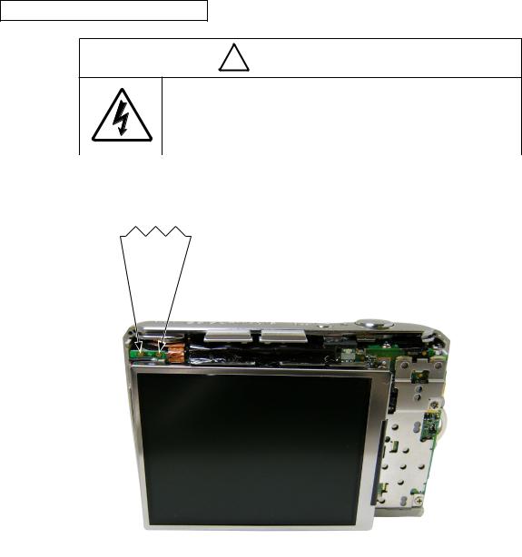
! WARNING
 There are high voltege parts inside. Be careful of this electric shock, when you remove the cover.
 You must discharge the main condenser according to the instruction of this repair manual after you remove the cover.
Points to notice for Lead-free solder products
Lead-free solder is used for this product.
For soldering work, the special solder and soldering iron are required.
Do not mix the lead-free solder with the conventional solder.
Use the special soldering iron respectively for lead-free solder and lead solder. They cannot be used in common.
Note : Before disassembling, remove the SD card and battery.
When disassembling, make sure to memorize the processing state of wires, screws to be fixed and their types, etc.
Because electrical parts are easily damaged by static electricity, make sure that you are well earthed/grounded.
- D L18 -
INC
VMA17003-R.3746.A
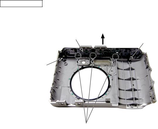
REAR COVER UNIT
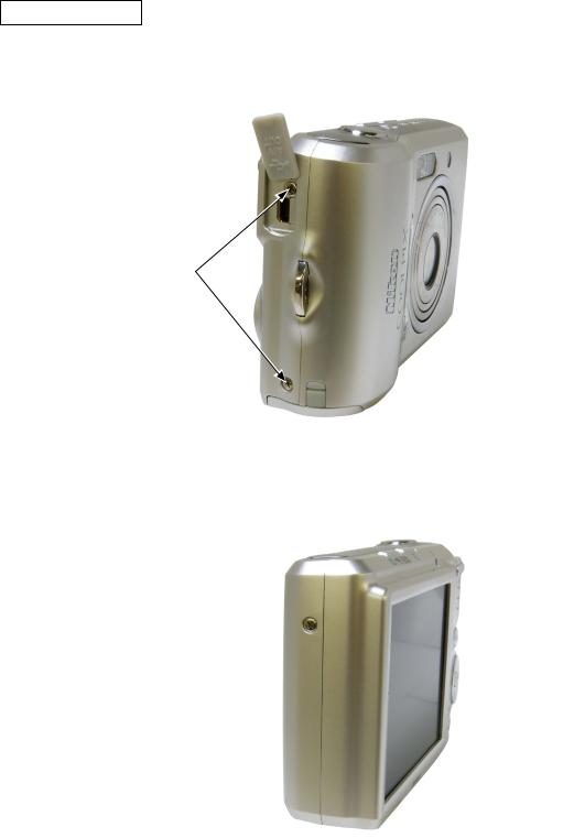
Open the USB COVER [#153].
Remove the two screws [#804].
USB COVER [#153] 
Screw [#804]
Remove the other screw [#804].
Screw [#804] 
- D L18 -

INC
VMA17003-R.3746.A
Remove the three screws [#804].
Screw [#804]
Open the BATTERY COVER UNIT [A001].
Unhook and remove the REAR COVER UNIT [E001].
 Unhook here.
 BATTERY COVER UNIT [A001]
Hook
 Hook
Hook
 Hook
Hook
 REAR COVER UNIT [E001]
Remove from the lower part.
- D L18 -

INC
VMA17003-R.3746.A
Remove the USB COVER [#153].
USB COVER [#153] 
- D L18 -
INC
VMA17003-R.3746.A
DISCHARGE OF MAIN CONDENSER
! WARNING
 There are high voltege parts inside. Be careful of this electric shock, when you remove the cover.
 You must discharge the main condenser according to the instruction of this repair manual after you remove the cover.
Discharge the main condenser. 2K Ω /5W
- D L18 -

INC
VMA17003-R.3746.A
LCD PANEL UNIT
Remove the LCD PANEL UNIT [I000].
LCD PANEL UNIT [I000]
Remove the FPC.
FPC
- D L18 -
INC
VMA17003-R.3746.A
FRONT COVER UNIT
Open the BATTERY COVER UNIT [A001].
Remove the FRONT COVER UNIT [C001].
Remove the front cover unit while slightly raising the release unit.
If the release unit is stuck, it may be damaged.
FRONT COVER UNIT [C001]
Open the front cover unit not completely but slightly, while keeping parallel to the main body.
BATTERY COVER UNIT [A001]
FRONT COVER UNIT [C001]
- D L18 -
INC
VMA17003-R.3746.A
MIDDLE COVER UNIT
Remove the two screws [#803].
Unhook at three places and remove the MIDDLE COVER UNIT [D001].
MIDDLE COVER UNIT [D001]
Screw [#803]
Screw [#803]
Unhook here
- D L18 -
INC
VMA17003-R.3746.A
BRACKET UNIT
Remove the six screws [#804].
Remove the BRACKET UNIT [J000].
Screw [#804]
BRACKET UNIT [J000]
Screw [#804]
Screw [#804]
- D L18 -
INC
VMA17003-R.3746.A
BATTERY COVER UNIT
Remove the SHAFT [#151].
Remove the BATTERY COVER UNIT [A001].
SHAFT [#151]
Open the BATTERY COVER UNIT [A001] slightly.
Be careful that opening [A001] all the way (completely) makes it impossible to remove the SHAFT [#151].
BATTERY COVER UNIT [A001]
- D10 L18 -

SPEED LIGHT PCB UNIT
Peel off the TAPE [#705].
Peel off the SPONGE [#753].Peel off the TAPE [#701].
Addition
Deletion
TAPE [#701]
Remove the soldering bridge (at two places).
Soldering bridge
Remove the three screws [#804].
Remove the SPEED LIGHT PCB UNIT [K000].
SPEED LIGHT PCB UNIT [K000]
Screw [#804] |
Screw [#804] |
INC
VMA17003-R.3746.A
TAPE [#705]
Changed page |
× |
- D11 L18 - |
March. 19. 2008 |
|
|
|
INC
VMA17003-R.3746.A
Unsolder the WIRES [Red] and [Black].
SPEED LIGHT PCB UNIT [K000] 
 WIRE [Red]
WIRE [Black]
- D12 L18 -

INC
VMA17003-R.3746.A
MAIN PCB UNIT
Unsolder the WIRES.
Unsolder the BATTERY CONTACT.
Remove the adhesive from the solder of the FPC, then remove the solder.
Remove the FPC (at two places).
Remove the LUG PLATE [#731].
BATTERY CONTACT
Unsolder the WIRES.
LUG PLATE [#731]
Solder of FPC
Unsolder the WIRE [Black].
FPC
- D13 L18 -
INC
VMA17003-R.3746.A
Remove the MAIN PCB UNIT [B001].
MAIN PCB UNIT [B001]
Be careful of the FPC.
- D14 L18 -

INC
VMA17003-R.3746.A
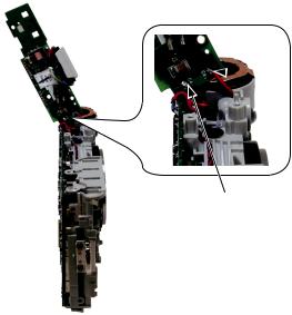
LENS UNIT
Remove the screw [#802].
Remove the WASHER [#751].
Screw [#802]
Screw [#802]
1]
Remove the adhesive from the screw [#801].Remove the screw [#801].
Screw [#801]
- D15 L18 -

INC
VMA17003-R.3746.A
Remove the screw [#802].
Remove the WASHER [#751].
Screw [#802]
 WASHER [#751]
 Screw [#802]
Remove the LENS UNIT [N055].
LENS UNIT [N055]
- D16 L18 -

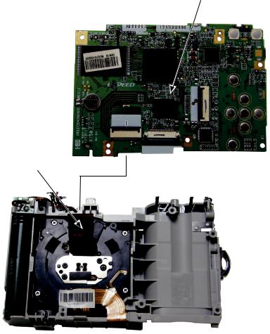
CCD UNIT
Remove the three screws [#717].
Remove the CCD UNIT [P045].
Screw [#717]
INC
VMA17003-R.3746.A
CCD UNIT [P045]
Screw [#717]
[#717]
CCD [P045]
- D17 L18 -
INC
VMA17003-R.3746.A
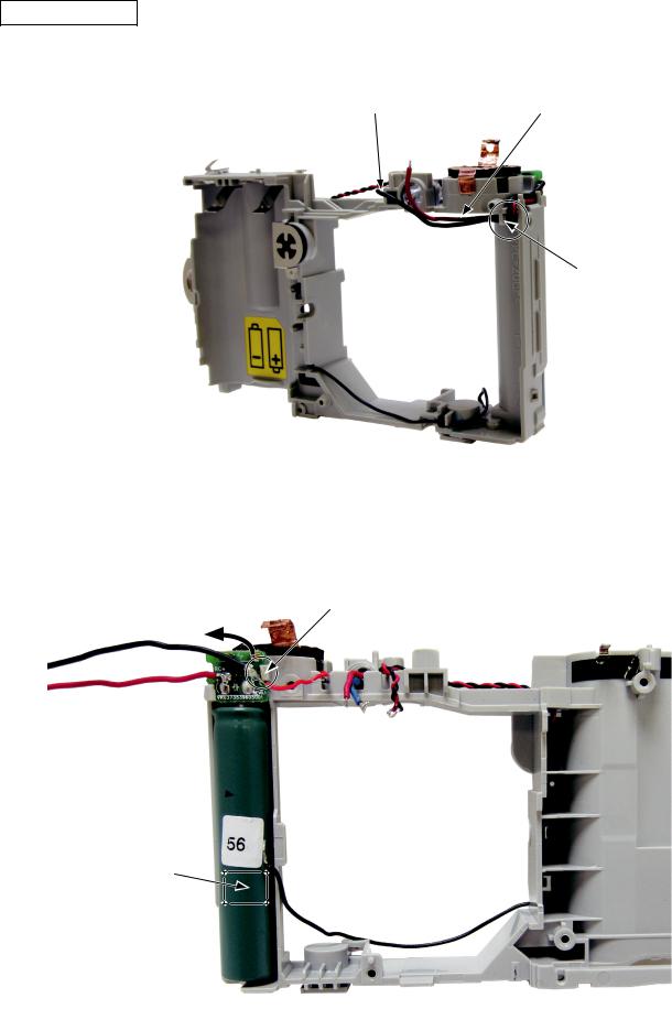
CONDENSER UNIT
Remove the WIRES [Red] and [Black].
WIRE [Black] |
WIRE [Red] |
Release from the hook.
Remove the CONDENSER UNIT [F000].
Be careful not to break the claw.
Remove the right side of the PCB first.
CONDENSER UNIT [F000] 
[F000] is adhered with the DOUBLE-STICK TAPE [#702].
- D18 L18 -
INC
VMA17003-R.3746.A
LED UNIT
Remove the LED UNIT [G000].
LED UNIT [G000] |
Remove the adhesive. |
- D19 L18 -
INC
VMA17003-R.3746.A
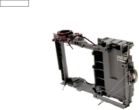
STRAP RING
Remove the two screws [#803].
Remove the STRAP RING [#150].
 STRAP RING [#150]
Screw [#803]
- D20 L18 -

INC
VMA17003-R.3746.A
ASSEMBLY
STRAP RING
Attach the strap ring [#150].
Tighten the two screws [#803].
 STRAP RING [#150]
Screw [#803]
Fit with the boss.
- A L18 -

INC
VMA17003-R.3746.A
LED UNIT
Mount the LED UNIT [G000].
LED UNIT [G000]
Adhesive: Cemedine high super 5
Put the WIRES [Blue] and [Red] into the grooves.
- A L18 -

INC
VMA17003-R.3746.A
CONDENSER UNIT
Mount the CONDENSER UNIT [F000].
Hook the left side of the PCB and push in the right side.
CONDENSER UNIT [F000] 
Arrange the WIRES [Black] and [Red] as shown in the figure.
WIRE [Red]
 Pass the WIRE through the notch of the PCB.
WIRE [Black]
- A L18 -

INC
VMA17003-R.3746.A
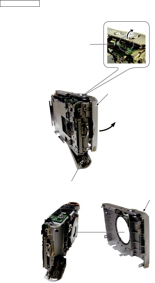
CHASSIS UNIT
Unhook each, and remove the microhpne-use lug plate. Direction of removal
Microhpne-use lug plate
Unhook here.
Solder the wire [#203] on the microhpne-use lug plate.
Reattach the microhpne-use lug plate by hooking to the chassis unit [H000], the way it used to be.
Direction of attachment
Microhpne-use lug plate
Hook
Additional page |
- A L18 - |
March. 19. 2008 |
 Loading...