


En
Fr
Ru
BLACK FORCE1000 1-4×24 IL SPEEDFORCE BLACK X1000 4-16×50SF IL X-MOA BLACK X1000 6-24×50SF IL X-MOA
BLACK X1000 4-16×50SF X-MOA BLACK X1000 4-16×50SF IL X-MRAD BLACK X1000 6-24×50SF IL X-MRAD
Instruction manual/Mode d'emploi/Инструкция по эксплуатации

CONTENTS
Instruction manual |
|
4 |
Mode d’emploi................................................................................................................................. |
|
42 |
Инструкция по эксплуатации |
|
80 |
3
|
|
Congratulations on your choice of a Nikon BLACK FORCE1000/BLACK X1000 Riflescope. Your new scope is the finest example of Nikon's rugged and durable construction and precision bright optics; important qualities |
|
En |
|||
|
for a serious shooter's riflescope. |
||
|
|
||
|
|
This riflescope was developed for the sportsperson who mainly uses it for shooting competitions. We hope that this product will enhance your enjoyment with stable accuracy and high performance. To mount the scope, |
|
|
|
a set of high-quality mounts which have a standard diameter of 30 mm (1.2 in.) are required. Follow the ring manufacturer's instructions for mounting procedures. After mounting the scope on your rifle, follow the |
|
|
|
procedures for reticle alignment. |
|
|
|
|
|
|
|
IMPORTANT INFORMATION |
|
|
|
IT IS IMPORTANT THAT YOUR NIKON RIFLESCOPE IS MOUNTED PROPERLY AND THAT CAREFUL CONSIDERATION BE GIVEN WHEN MOUNTING YOUR NIKON RIFLESCOPE ON A FIREARM. |
|
|
|
UNLESS YOU ARE EXPERIENCED IN MOUNTING RIFLESCOPES, WE HIGHLY RECOMMEND THAT YOUR NIKON RIFLESCOPE BE MOUNTED ON YOUR FIREARM BY AN EXPERIENCED, REPUTABLE GUNSMITH. |
|
|
|
THE USER ASSUMES ALL RESPONSIBILITY AND LIABILITY FOR HAVING THE NIKON RIFLESCOPE PROPERLY MOUNTED TO A FIREARM AND USING THE NIKON RIFLESCOPE PROPERLY. |
|
|
|
ALWAYS CHECK THE CONDITION OF YOUR MOUNTING SYSTEM PRIOR TO USING YOUR FIREARM. |
|
|
|
|
4

SUPPLIED ITEM(S)
Body······································ 1 piece Eyepiece cap1························ 1 piece Objective cap1······················· 1 piece
Battery (3V Lithium battery: CR2032)2·····················1 piece |
En |
|
|
Battery-chamber cover opener2································1 piece |
|
Sunshade3··································································1 piece |
|
1Rubber band linked (This type connects the objective and eyepiece caps using a rubber band.)
2Included for IL models (illuminated reticle models; illumination control functions are incorporated in the side focus adjustment section) only.
3Included except for BLACK FORCE1000 1-4×24 IL SPEEDFORCE.
Caution
(1)Do NOT look at the sun through the riflescope. It will permanently damage your eye. This precaution applies to all optical devices, such as cameras and binoculars.
(2)The riflescope is effectively sealed against moisture and dust. You may use your scope safely either in the rain or in dusty climates. To preserve the appearance of the scope, we recommend that it be dried and cleaned prior to storage. Use a soft cloth for cleaning metal surfaces and use photographic lens tissue to clean the scope's lenses.
(3)Never leave the device in the sun for extended periods without the Eyepiece/Objective cap. The objective lens and eyepiece can function as a burning glass and damage the interior components.
(4)When not in use for an extended period, please remove the battery from the body.
(5)If the battery-chamber cover is damaged, or if it emits a strange sound due to dropping or some other cause, remove the battery immediately and stop using.
5
|
|
Caution (Lithium battery) |
En |
||
|
|
If handled incorrectly, the battery may rupture and leak, corroding equipment and staining clothing. Be sure to observe the following: |
|
|
•Install the battery with the + and - poles positioned correctly. |
|
|
•The battery should be removed when exhausted or during extended periods of non-use. |
|
|
•Do not short the end terminal of the battery chamber. |
|
|
•Do not carry together with keys or coins in a pocket or bag, it may short and cause overheating. |
|
|
•Do not expose the battery to water, or a flame. Never disassemble the battery. |
|
|
•Do not charge the lithium battery. |
|
|
•If liquid from a damaged battery comes into contact with clothing or skin, rinse immediately with plenty of water. If liquid from a damaged battery enters the eyes, rinse immediately with clean water, then consult a doctor. |
|
|
•When disposing of the battery, follow your local area regulations. |
|
|
|
6

This device complies with Part 15 of the FCC Rules. Operation is subject to the following two conditions: |
|
En |
(1)This device may not cause harmful interference, and
(2)This device must accept any interference received, including interference that may cause undesired operation.
This equipment has been tested and found to comply with the limits for a Class B digital device, pursuant to Part 15 of the FCC Rules and to EU EMC directive. These limits are designed to provide reasonable protection against harmful interference in a residential installation. This equipment generates, uses and can radiate radio frequency energy and, if not installed and used in accordance with the instructions, may cause harmful interference to radio communications. However, there is no guarantee that interference will not occur in a particular installation. If this equipment does cause harmful interference to radio or television reception, which can be determined by turning the equipment off and on, the user is encouraged to try to correct the interference by one or more of the following measures:
•Reorient or relocate the receiving antenna.
•Increase the separation between the equipment and receiver.
•Consult the dealer or an experienced radio/TV technician for help.
This Class B digital apparatus meets all requirements of the Canadian Interference-Causing Equipment Regulations.
7

|
|
Symbol for separate collection applicable in European countries |
Symbol for separate collection applicable in European countries |
|||||
En |
||||||||
|
|
This symbol indicates that this battery is to be collected separately. |
|
|
|
This symbol indicates that this product is to be collected separately. |
||
|
|
|
|
|
||||
|
|
The following apply only to users in European countries. |
|
|
|
The following apply only to users in European countries. |
||
|
|
• |
Thisbatteryisdesignatedforseparatecollectionatanappropriatecollectionpoint.Do |
|
|
|
• |
Thisproductisdesignatedforseparatecollectionatanappropriatecollectionpoint.Do |
|
|
|
not dispose of as household waste. |
|
|
|
|
not dispose of as household waste. |
|
|
|
|
|
|
|
||
|
|
|
|
|
|
|
||
|
|
• |
For more information, contact the retailer or the local authorities in charge of waste |
|
|
|
• |
For more information, contact the retailer or the local authorities in charge of waste |
|
|
|
management. |
|
|
|
|
management. |
|
|
|
|
|
|
|
|
|
When setting the reticle for shooting, you should determine your standard range and then adjust the reticle based upon that target distance. For targets which vary from that standard distance, according to personal preference, you may simply adjust the position of the reticle in relation to your target, or you may wish to use the procedure for trajectory compensation.
We hope that you will enjoy your new Nikon Riflescope for many years to come. Enjoy using it, and above all, always follow safe shooting procedures.
N.B. Export of the products* in this manual may be controlled under the laws and relatives of the exporting country. Appropriate export procedure, such as obtaining of export license, shall be required in case of export. *Products: Hardware and its technical information (including software)
8

1. Nomenclature
•BLACK FORCE1000 1-4×24 IL SPEEDFORCE
0 b a
Fig. 1-1
1 Objective lens |
En |
|
2Eyepiece lens
3Elevation adjustment turret
4Windage adjustment turret
5Eyepiece adjustment
6Power index
7Power scale
8Power selector ring
9Diopter index dot
0 Rheostat intensity dial
ARheostat intensity index
BBattery-chamber cover
9

•BLACK X1000 4-16×50SF X-MOA
En
|
|
1 Objective lens |
|
|
2 Eyepiece lens |
|
|
3 Elevation adjustment turret |
|
|
4 Windage adjustment turret |
|
|
5 Eyepiece adjustment |
|
|
6 Power index |
|
|
7 Power scale |
|
|
8 Power selector ring |
|
|
9 Diopter index dot |
a 0 |
b |
0 Side focus adjustment turret |
|
|
|
Fig. 1-2 |
|
A Distance scale |
|
|
B Distance index |
|
|
C Sunshade |
10
•BLACK X1000 4-16×50SF IL X-MOA
•BLACK X1000 4-16×50SF IL X-MRAD
•BLACK X1000 6-24×50SF IL X-MOA
•BLACK X1000 6-24×50SF IL X-MRAD
| <![if ! IE]> <![endif]>50 |
<![if ! IE]> <![endif]>60 |
<![if ! IE]> <![endif]>75 |
<![if ! IE]> <![endif]>100 |
f a0c e d b
Fig. 1-3
1 Objective lens |
|
|
En |
||
2 Eyepiece lens |
||
|
||
3 Elevation adjustment turret |
|
|
4 Windage adjustment turret |
|
|
5 Eyepiece adjustment |
|
|
6 Power index |
|
|
7 Power scale |
|
|
8 Power selector ring |
|
|
9 Diopter index dot |
|
|
0 Side focus adjustment turret |
|
|
A Distance scale |
|
|
B Distance index |
|
|
C Rheostat intensity dial |
|
|
D Rheostat intensity index |
|
|
E Battery-chamber cover |
|
|
F Sunshade |
|
11

|
Adjustment mechanism of BLACK FORCE1000 Riflescope |
||
En |
|||
Elevation adjustment |
Windage adjustment |
||
|
|||
|
|
1 Adjustment turret |
|
Shipped attached to |
2 Screw for adjustment turret |
|
riflescope |
||
3 Cap for adjustment turret |
||
|
||
|
Shipped attached to |
|
|
riflescope |
Fig. 1-5
Fig. 1-4
12

Adjustment mechanism of BLACK X1000 Riflescope Series |
En |
|
Elevation adjustment |
Windage adjustment |
|
1 Adjustment turret |
Shipped attached to |
2 Screw for adjustment turret |
|
|
riflescope |
Shipped attached to |
|
|
|
riflescope |
Fig. 1-7
Fig. 1-6
13

En
14
2. Specifications
Model |
|
BLACK FORCE1000 1-4×24 IL SPEEDFORCE |
BLACK X1000 4-16×50SF X-MOA |
BLACK X1000 4-16×50SF IL X-MOA |
BLACK X1000 4-16×50SF IL X-MRAD |
BLACK X1000 6-24×50SF IL X-MOA |
BLACK X1000 6-24×50SF IL X-MRAD |
Actual magnification |
(×) |
1-4 |
4-16 |
4-16 |
4-16 |
6-24 |
6-24 |
Effective objective diameter |
(mm) |
24 |
50 |
50 |
50 |
50 |
50 |
Exit pupil*1 |
(mm) |
24-6 |
12.5-3.1 |
12.5-3.1 |
12.5-3.1 |
8.3-2.1 |
8.3-2.1 |
Eye relief *1 |
(mm)/(in.) |
104.1-96.5/4.1-3.8 |
101.6-91.4/4.0-3.6 |
101.6-91.4/4.0-3.6 |
101.6-91.4/4.0-3.6 |
101.6-88.9/4.0-3.5 |
101.6-88.9/4.0-3.5 |
Tube diameter |
(mm)/(in.) |
30/1.2 |
30/1.2 |
30/1.2 |
30/1.2 |
30/1.2 |
30/1.2 |
Objective outside diameter |
(mm)/(in.) |
30/1.2 |
60.3/2.4 |
60.3/2.4 |
60.3/2.4 |
60.3/2.4 |
60.3/2.4 |
Eyepiece outside diameter |
(mm)/(in.) |
44/1.7 |
44/1.7 |
44/1.7 |
44/1.7 |
44/1.7 |
44/1.7 |
Adjustment graduation |
|
1 click: 1/2 MOA*2 |
1 click: 1/4 MOA*2 |
1 click: 1/4 MOA*2 |
1 click: 0.1 MRAD*3 |
1 click: 1/4 MOA*2 |
1 click: 0.1 MRAD*3 |
|
|
1 revolution: 24 MOA*2 |
1 revolution: 12 MOA*2 |
1 revolution: 12 MOA*2 |
1 revolution: 5 MRAD*3 |
1 revolution: 12 MOA*2 |
1 revolution: 5 MRAD*3 |
|
|
1 revolution: 48 clicks |
1 revolution: 48 clicks |
1 revolution: 48 clicks |
1 revolution: 50 clicks |
1 revolution: 48 clicks |
1 revolution: 50 clicks |
Max. internal adjustment |
|
350 MOA*2 |
90 MOA*2 |
90 MOA*2 |
25 MRAD*3 |
60 MOA*2 |
17 MRAD*3 |
Parallax setting |
(m)/(yd.) |
91.4/100 |
45.7-∞/50-∞ |
45.7-∞/50-∞ |
45.7-∞/50-∞ |
45.7-∞/50-∞ |
45.7-∞/50-∞ |
Field of view at 100 m*1 |
(m) |
36.7-9.1 |
9.1-2.3 |
9.1-2.3 |
9.1-2.3 |
6.0-1.5 |
6.0-1.5 |
Field of view at 100 yd.*1 |
(ft) |
110.1-27.2 |
27.2-6.8 |
27.2-6.8 |
27.2-6.8 |
18.0-4.5 |
18.0-4.5 |
Length (a) |
(mm)/(in.) |
266/10.5 |
375/14.8 |
375/14.8 |
375/14.8 |
387/15.2 |
387/15.2 |
Mount length (b) |
(mm)/(in.) |
75.5/3.0 |
81.1/3.2 |
81.1/3.2 |
81.1/3.2 |
81.1/3.2 |
81.1/3.2 |
Mount length (c) |
(mm)/(in.) |
34.0/1.3 |
35.8/1.4 |
35.8/1.4 |
35.8/1.4 |
35.8/1.4 |
35.8/1.4 |
Mount length (d) |
(mm)/(in.) |
52.0/2.0 |
51.0/2.0 |
51.0/2.0 |
51.0/2.0 |
51.0/2.0 |
51.0/2.0 |
Weight |
(g)/(oz) |
465/16.4 |
675/23.8 |
690/24.3 |
690/24.3 |
710/25.0 |
710/25.0 |
Power Source |
|
CR2032 |
– |
CR2032 |
CR2032 |
CR2032 |
CR2032 |
Reticle Intensity Adjustment |
|
10 steps*4 |
– |
10 steps*4 |
10 steps*4 |
10 steps*4 |
10 steps*4 |
EMC |
|
FCC Part15 subpartB ClassB |
– |
FCC Part15 subpartB ClassB |
FCC Part15 subpartB ClassB |
FCC Part15 subpartB ClassB |
FCC Part15 subpartB ClassB |
|
|
CE EMC DIRECTIVE AS/NZS |
CE EMC DIRECTIVE AS/NZS |
CE EMC DIRECTIVE AS/NZS |
CE EMC DIRECTIVE AS/NZS |
CE EMC DIRECTIVE AS/NZS |
|
|
|
|
|||||
Environment |
|
RoHS WEEE |
– |
RoHS WEEE |
RoHS WEEE |
RoHS WEEE |
RoHS WEEE |
Structure |
|
|
|
Waterproof (up to 1 meter for 10 minutes) and nitrogen gas purged |
|
|
|
*1 (at minimum magnification)-(at maximum magnification)
*2 MOA = Minute of Angle
*3 MRAD = milliradian (mil)
*4 Illumination intensity: 10 steps, with OFF positions between each step (change in the order of 1, OFF, 2, OFF, 3, OFF...10, OFF)
Objective |
|
|
|
|
|
|
|
|
|
|
|
Eyepiece |
||||||
|
|
|
|
|
|
|
|
|
|
|
|
|
|
|
|
|
|
|
|
|
|
|
|
|
|
|
|
|
|
|
|
|
|
|
|
|
|
|
|
|
|
|
|
|
|
|
|
|
|
|
|
|
|
|
|
|
|
|
|
|
|
|
|
|
|
|
|
|
|
|
|
|
|
|
|
|
|
|
|
|
|
|
|
|
|
|
|
|
|
|
|
|
|
|
|
|
|
|
|
|
|
|
|
|
|
|
|
|
|
|
|
|
|
|
|
|
|
|
|
|
|
|
|
|
|
|
|
|
|
|
|
|
|
|
|
|
|
|
|
|
|
|
|
|
|
|
|
|
|
|
|
|
|
|
|
|
|
|
|
|
|
|
|
|
|
|
|
|
|
|
|
|
|
|
|
|
|
|
|
|
|
|
|
|
|
|
|
|
|
|
|
|
|
|
|
|
|
|
|
|
|
|
|
|
|
|
|
|
|
|
|
|
|
|
|
|
|
|
|
|
|
|
|
|
|
|
|
Letters a to d in the diagram above refer to lengths (a) to (d) shown in the Specifications table.
3. Instructions |
En |
|
(1) Inserting the battery and adjusting the illumination intensity (IL models only)
CAUTION: When installing batteries, make sure the firearm is unloaded. Use safe firearm handling practices at all times.
The IL models are powered by one 3V lithium battery (CR2032). When your reticle flashes or does not light, you need to replace the battery.
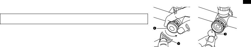
How to insert the battery |
|
|
1Hold the rheostat intensity dial tightly and turn the battery-chamber cover 1counter-clockwise with the battery-chamber |
|
|
cover opener 2(Fig. 3-1). |
Fig. 3-1 |
Fig. 3-2 |
2Insert one 3V lithium battery 3into the chamber with the positive (+) side facing up (Fig. 3-2). |
|
|
3Put the cover back and turn it clockwise with the battery-chamber cover opener until the cover is firmly secured. |
|
|
15

|
How to adjust the illumination intensity |
|
En |
||
Turn the rheostat intensity dial to the desired intensity* (Fig.3-3). |
||
|
||
|
When not in use, be sure to set the dial to (OFF). |
|
|
Illumination will automatically turn off after approximately 2 hours of non-operation. |
|
|
* The illumination intensity is available in 10 steps. When you rotate the rheostat intensity dial, the illumination intensity changes in the |
|
|
order of 1, OFF, 2, OFF, 3, OFF...10, OFF. |
•The IL models come with a 3V lithium battery (CR2032).
•Replace the battery if your riflescope is ever submerged in water or if water enters the battery chamber.

 Rheostat intensity index Rheostat intensity dial
Fig. 3-3
16

(2)Focusing
1Look through the eyepiece with your eye positioned about 10 cm (4 in.) away from the eyepiece to see the SPEEDFORCE reticle (Fig. 3-4), the X-MOA reticle (Fig. 3-5), or the X-MRAD reticle (Fig. 3-6). Be sure your eye is positioned with proper alignment and with proper eye relief, otherwise the view will“black out.”
2Point the objective end of the scope at the sky (do NOT point it at the sun) or at a plain unpatterned wall.
3Turn the eyepiece adjustment counter-clockwise and then turn it clockwise until the reticle appears sharp.
Notice: Reticle images shown in this manual are representation only. Actual images may vary depending on the magnification and the reticle plane.
(3)Magnification
•Nikonriflescopeshavevariablemagnification.Fordetails,see“2.Specifications”.
To change powers, rotate the power selector ring until the desired magnification appears adjacent to the power index.
SPEEDFORCE reticle |
X-MOA reticle |
En |
|
|
Fig. 3-4 |
Fig. 3-5 |
X-MRAD reticle
Fig. 3-6
17
|
(4) Adjustment of the riflescope |
|
En |
||
Sighting through the riflescope, align the rifle with your aiming point on the target and shoot a trial round. If the bullet does not hit the aiming point, adjust the elevation and windage as follows: |
||
|
||
|
•If the bullet hits under the aiming point, turn the elevation adjustment turret (counter-clockwise) in the direction of the arrow marked“U” for up. If the bullet hits high, turn the elevation adjustment turret (clock- |
|
|
wise) in the direction of the arrow marked“D” for down. |
|
|
•If the bullet hits to the right of the aiming point, turn the windage adjustment turret (clockwise) in the direction of the arrow marked“L” for left. If the bullet hits to the left of the aiming point, turn the windage |
|
|
adjustment turret (counter-clockwise) in the direction of the arrow marked“R” for right. |
|
|
•After the reticle has been adjusted to the point of impact, replace the turret cap for both the windage and elevation adjustment turrets (BLACK FORCE1000 1-4x24 IL SPEEDFORCE only). |
|
|
(5) Zero setting of adjustment turret |
|
|
The elevation adjustment and windage adjustment turrets have a retracting system. After the reticle has been adjusted to match the point of impact, pull up the elevation adjustment or windage adjustment turret |
|
|
to disengage. The turret can now be turned freely. Align the zero number to the index line to set the zero setting, and then release the turret. The turret automatically retracts to the original position. |
18
(6) Adjustable side focus |
|
|
En |
||
The BLACK X1000 Riflescope Series includes a side-focus adjustment that allows precise focusing of the reticle on the same focal plane as the target image from 45.7 m (50 yd.) to infinity. Thus, parallax can be |
||
|
||
eliminated and sight alignment will be accurate. The marked distance scale can be used as a reference guide. |
|
Note:
•The windage and elevation scales of BLACK FORCE1000 1-4×24 IL SPEEDFORCE are calibrated in divisions of 1/2 minute of angle (MOA) with a click at intervals of 1/2 minute of angle (1 division).
•The windage and elevation scales of BLACK X1000 4-16×50SF X-MOA, BLACK X1000 4-16×50SF IL X-MOA, and BLACK X1000 6-24×50SF IL X-MOA are calibrated in divisions of 1/4 minute of angle (MOA) with a click at intervals of 1/4 minute of angle (1 division).
The windage and elevation scales of BLACK X1000 4-16×50SF IL X-MRAD and BLACK X1000 6-24×50SF IL X-MRAD are calibrated in divisions of 0.1 Millradian (MRAD) per click.
•When adjusting the reticle to the point of aim, remember that 1 minute of angle (MOA) equals approximately 2.54 cm (1 in.) at 91.44 m (100 yd.).
Therefore, if the impact point is 5.08 cm (2 in.) low and 2.54 cm (1 in.) right at 91.44 m (100 yd.) parallax setting, you should adjust 2 minutes of angle up and 1 minute of angle left. In the case of 45.72 m (50 yd.) parallax setting, the adjusting value is 2×. In the case of 68.58 m (75 yd.) parallax setting, the adjusting value is 1.5×.
•When adjusting the reticle to the point of aim, remember that 0.1 Millradian equals approximately 1 cm at 100 m.
Therefore, if the impact point is 2 cm low and 1 cm right at 100 m parallax setting, you should adjust 0.2 Millradian up and 0.1 Millradian left.
19
|
4. Utilizing the SPEEDFORCE reticle, X-MOA reticle, or X-MRAD reticle |
|
En |
||
These reticles are designed to compensate for the trajectory of your firearm. |
||
|
||
|
Please note that the reticle is based upon ballistic information and may or may not meet the same results for you as there are many variables that come into play such as: |
|
|
•ActualVelocity(Ammunitionmanufactures’informationinregardstomuzzlevelocitymayormaynotmatchthevelocityyourfirearmproduces.Thebestwaytodeterminetheactualmuzzlevelocityforyourfirearmis |
|
|
to use a chronograph). |
|
|
•Temperature |
|
|
•Humidity |
|
|
•Altitude |
|
|
•BarometricPressure |
|
|
•Conditionandinherentaccuracyofthefirearm |
|
|
•Themountingsystemandhowtrueitpositionsthescopetothecenterlineofthebore |
20
SPEEDFORCE Reticle
The SPEEDFORCE reticle (Fig. 4-1) was designed for both reaction-speed target acquisition and engagement, and for intermediate-range target holdovers using BDC circles and hash marks. The SPEEDFORCE is an MOA subtension reticle engineered to enable shooters to continue momentum from target to target and thus, excel in close-to-medium range engagements both in competition and field use.
When the riflescope is set at its lowest 1× magnification, the reticle’s illuminated double horseshoe serves as quick reference for centering on the target with both eyes open, as well as for establishing moving-target leads.
En
Fig. 4-1
21

En
22
The SPEEDFORCE reticle’s 1-MOA-thick inner horseshoe has an inside |
|
|
|
|
|
|
|
|
|
|
|
|
|
|
|
|
|
|
|
|
|
|
|
|
|
|
|
|
|
|
|
|
|
|
|
|
|
|
|
|
|
|
|
|
|
|
|
|
|
|
|
|
|
|
|
|
|
|
|
|
|
|
|
|
|
|
|
|
|
|
|
|
|
|
|
|
|
|
|
|
|
|
|
|
|
|
|
|
|
|
|
|
|
|
|
|
|
|
|
|
|
|
|
|
|
|
|
|
|
|
|
|
|
|
|
|
|
|
|
|
|
|
|
|
|
|
|
|
|
|
|
|
|
|
|
|
|
|
|
|
|
|
|
|
|
|
|
|
|
|
|
|
|
|
|
|
|
|
|
|
|
|
|
|
|
|
|
|
|
|
|
|
|
|
|
|
|
|
|
|
|
|
|
|
|
|
|
|
|
|
|
|
|
|
|
|
|
|
|
|
|
||
diameter of 17 MOA. The B-Zone of a 3-Gun target, the breadth of an |
|
|
|
|
|
|
|
|
|
|
|
|
|
|
|
|
|
|
|
|
|
|
|
|
|
|
|
|
|
|
|
|
|
|
|
|
|
|
|
|
|
|
|
|
|
|
|
|
|
|
|
|
|
|
|
|
|
|
|
|
|
|
|
|
|
|
|
|
|
|
|
|
|
|
|
|
|
|
|
|
|
|
|
|
|
|
|
|
|
|
|
|
|
|
|
|
|
|
|
|
|
IDPA*1 or IPSC*2 target and many others can be engaged quickly by |
|
|
|
|
|
|
|
|
|
|
|
|
|
|
|
|
|
|
|
|
|
|
|
|
|
|
|
|
|
|
|
|
|
|
|
|
|
|
|
|
|
|
|
|
|
|
|
|
|
|
|
|
|
|
|
|
|
|
|
|
|
|
|
|
|
|
|
|
|
|
|
|
|
|
|
|
|
|
|
|
|
|
|
|
|
|
|
|
|
|
|
|
|
|
|
|
|
|
|
|
|
centering the double horseshoe like a red-dot or by framing the target |
|
|
|
|
|
|
|
|
|
|
|
|
|
|
|
|
|
|
|
|
|
|
|
|
|
|
|
|
|
|
|
|
|
|
|
|
|
|
|
|
|
|
|
|
|
|
|
|
|
|
|
|
|
|
|
|
|
|
|
|
|
A |
|
|
|
|
|
|
|
|
|
|
|
|
|
|
|
|
|
|
|
|
|
|
|
|
|
|
|
|
|
|
|
|
|
|
|
|
|||
within the inner horseshoe at 100 yards (Fig. 4-2, 4-3). |
|
|
|
|
|
|
|
|
|
|
|
|
|
|
|
|
|
|
|
|
|
|
|
|
|
|
|
|
|
|
|
|
|
|
|
|
|
|
|
|
|
|
|
|
|
|
|
|
|
|
|
|
|
|
|
|
|
|
|
|
|
B |
|
|
|
|
|
|
|
|
|
|
|
|
|
|
|
|
|
|
|
|
|
|
|
|
|
|
|
|
|
|
|
|
|
|
|
|
|||
|
|
|
|
|
|
|
|
|
|
|
|
|
|
|
|
|
|
|
|
|
|
|
|
|
|
|
|
|
|
|
|
|
|
|
|
|
|
|
|
|
|
|
|
|
|
|
|
|
|
|
|
|
|
|
|
|
|
|
|
|
|
|
|
|
|
|
|
|
|
|
|
|
|
|
|
|
|
|
|
|
|
|
|
|
|
|
|
|
|
|
|
|
|
|
|
|
|||||
|
|
|
|
|
|
|
|
|
|
|
|
|
|
|
|
|
|
|
|
|
|
|
|
|
|
|
|
|
|
|
|
|
|
|
|
|
|
|
|
|
|
|
|
|
|
|
|
|
|
|
|
|
|
|
|
|
|
|
|
|
A |
|
|
|
|
|
|
|
|
|
|
|
|
|
|
|
|
|
|
|
|
|
|
|
|
|
|
|
|
|
|
|
|
|
|
|
|
||||
Similarly, the reticle’s two “+” marks flanking the 2 MOA center dot |
|
|
|
|
|
|
|
|
|
|
|
|
|
|
|
|
|
|
|
|
|
|
|
|
|
|
|
|
|
|
|
|
|
|
|
|
|
|
|
|
|
|
|
|
|
|
|
|
|
|
|
|
|
|
|
|
|
|
|
|
|
|
|
|
|
|
|
|
|
|
|
|
|
|
|
|
|
|
|
|
|
|
|
|
|
|
|
|
|
|
|
|
|
|
|
|
|
||||
|
|
|
|
|
|
|
|
|
|
|
|
|
|
|
|
|
|
|
|
|
|
|
|
|
|
|
|
|
|
|
|
|
|
|
|
|
|
|
|
|
|
|
|
|
|
|
|
|
|
|
|
|
|
|
|
|
|
|
|
|
|
|
|
|
|
|
|
|
|
|
|
|
|
|
|
|
|
|
|
|
|
|
|
|
|
|
|
|
|
|
|
|
|
|
|
|
|
|
|
||
are spaced just under 12 MOA (from outer edge to outer edge), which |
|
|
|
|
|
|
|
|
|
|
|
|
|
|
|
|
|
|
|
|
|
|
|
|
|
|
|
|
|
|
|
|
|
|
|
|
|
|
|
|
|
|
|
|
|
|
|
|
|
|
|
|
|
|
|
|
|
|
|
|
|
|
|
|
|
|
|
|
|
|
|
|
|
|
|
|
|
|
|
|
|
|
|
|
|
|
|
|
|
|
|
|
|
|
|
|
|
|
|
|
|
frame the outer edge of the C-Zone of a 3-Gun target at 100 yards. The |
|
|
|
|
|
|
|
|
|
|
|
|
|
|
|
|
|
|
|
|
|
|
|
|
|
|
|
|
|
|
|
|
|
|
|
|
|
|
|
|
|
|
|
|
|
|
|
|
|
|
|
|
|
|
|
|
|
|
|
|
|
C |
|
|
|
|
|
|
|
|
|
|
|
|
|
|
|
|
|
|
|
|
|
|
|
|
|
|
|
|
|
|
|
|
|
|
|
|
|||
|
|
|
|
|
|
|
|
|
|
|
|
|
|
|
|
|
|
|
|
|
|
|
|
|
|
|
|
|
|
|
|
|
|
|
|
|
|
|
|
|
|
|
|
|
|
|
|
|
|
|
|
|
|
|
|
|
|
|
|
|
|
|
|
|
|
|
|
|
|
|
|
|
|
|
|
|
|
|
|
|
|
|
|
|
|
|
|
|
|
|
|
|
|
|
|
|
|||||
|
|
|
|
|
|
|
|
|
|
|
|
|
|
|
|
|
|
|
|
|
|
|
|
|
|
|
|
|
|
|
|
|
|
|
|
|
|
|
|
|
|
|
|
|
|
|
|
|
|
|
|
|
|
|
|
|
|
|
|
|
|
|
|
|
|
|
|
|
|
|
|
|
|
|
|
|
|
|
|
|
|
|
|
|
|
|
|
|
|
|
|
|
|
|
|
|
|||||
inner and outer horseshoes also help frame the target quickly. |
|
|
|
|
|
|
|
|
|
|
|
|
|
|
|
|
|
|
|
|
|
|
|
|
|
|
|
|
|
|
|
|
|
|
|
|
|
|
|
|
|
|
|
|
|
|
|
|
|
|
|
|
|
|
|
|
|
|
|
|
|
D |
|
|
|
|
|
|
|
|
|
|
|
|
|
|
|
|
|
|
|
|
|
|
|
|
|
|
|
|
|
|
|
|
|
|
|
|
|||
|
|
|
|
|
|
|
|
|
|
|
|
|
|
|
|
|
|
|
|
|
|
|
|
|
|
|
|
|
|
|
|
|
|
|
|
|
|
|
|
|
|
|
|
|
|
|
|
|
|
|
|
|
|
|
|
|
|
|
|
|
|
|
|
|
|
|
|
|
|
|
|
|
|
|
|
|
|
|
|
|
|
|
|
|
|
|
|
|
|
|
|
|
|
|
|
|
|||||
At 100 yards, a Pepper Popper is framed by the outer edges of the reti- |
Fig. 4-2: |
3-Gun target |
|
|
|
|
|
|
|
Fig. 4-4: Pepper Popper |
|
|
|
|
|
|
|
|
|||||
cle’s two“+” marks, making target acquisition fast and easy (Fig. 4-4). |
|
|
|
|
|
|
|
||||
|
|
|
|
|
|
|
|
|
|
||
*1 |
IDPA Target is the official target of the International Defensive Pistol |
|
|
|
|
|
|
|
|
|
|
|
|
|
|
|
|
|
|
|
|
||
|
|
|
|
|
|
|
|
|
|
||
|
|
Fig. 4-3: IPSC target |
|||||||||
|
Association |
|
|
||||||||
*2 |
IPSC Target is the official target of the International Practical Shooting |
|
|
|
|
|
|
|
|
|
|
|
Confederation |
|
|
|
|
|
|
|
|
|
|

Keeping the reticle’s various reference points in mind, split-second range estimates can be made easily for shooting both up-close |
|
|
|
|
|
|
|
|
|
|
|
|
|
En |
|
at 1× or at longer ranges using the full 4× magnification*. By knowing your target’s size you can use the SPEEDFORCE to estimate |
|
|
|
|
|
|
|
|
|
|
|
|
|
|
|
range, and for other applications such as holdovers, windage hold-offs and moving target leads. |
|
|
|
|
|
|
|
The SPEEDFORCE reticle was designed around the velocity and bullet drops of the factory .223 Rem. with 55 gr. bullet (BC 0.240) |
|
|
|
|
|
|
|
and a muzzle velocity of approx 3240 fps (feet per second). The two“ballistic circles” beneath the center dot offer see through aiming |
|
|
|
|
|
|
|
points at ranges of approximately 300 yards (274.3 meters) and 400 yards (365.8 meters) when zeroed at 100 yards (91.4 meters) |
|
|
|
|
|
|
|
(Fig. 4-5). |
|
|
|
|
|
|
|
* The BLACK FORCE1000 Riflescope has the SPEEDFORCE reticle placed in the riflescope’s second focal plane, so when shooting at ex- |
|
|
|
|
|
|
|
|
|
|
|
|
|
|
|
|
|
|
|
|
|
|
|
tended distances utilizing holdover, all corrections, ranging and other measurements using the indicated reticle subtensions should be |
|
|
|
|
|
|
|
|
|
|
|
|
|
|
|
done at 4×. |
|
|
|
|
|
100 yd. (91.4 m) - Center |
|
|
|
|
|
|
|||
|
|
|
|
|
|||
|
|
|
|
|
|
200 yd. (182.9 m) - Bottom of Circle |
|
|
|
|
|
|
|
||
|
|
|
|
|
|
300 yd. (274.3 m) |
|
|
Fig. 4-5 |
||||||
|
400 yd. (365.8 m) |
||||||
|
|
|
|
|
|
||
23
|
Using SPEEDFORCE for Wind Hold |
|
|
|
|
|
|
|
|
|
|
|
|
|
|
|
En |
|
|
|
|
|
|
|
|
|
|
|
|
|
|
||
The BLACK FORCE1000 Riflescope utilizes capped adjustment turrets to prevent inadvertent movements during com- |
|
|
|
|
|
|
|
|
|
|
|
|
|
|
||
|
|
|
WIND |
|
|
|
|
|
||||||||
|
petition or rugged, active use. For this reason, the SPEEDFORCE reticle was designed for fast elevation or windage |
|
|
|
|
|
|
|
|
|||||||
|
|
|
|
|
|
|
|
|
|
|
|
|
|
|
|
|
|
correction on the initial shot, as well as on any follow-up shots. When adjusting for wind hold using the reticle, you can |
|
|
|
|
|
|
|
|
|
|
|
|
|
|
|
|
use the various subtensions between the center dot and outboard horseshoes, “+ mark,” or hashmarks on the reticle’s |
|
|
|
|
|
|
|
|
|
|
|
|
|
|
|
|
horizontal wire like a ruler to help reference your specified point. For example, if the wind speed value has you holding |
|
|
|
|
|
|
|
|
|
|
|
|
|
|
|
|
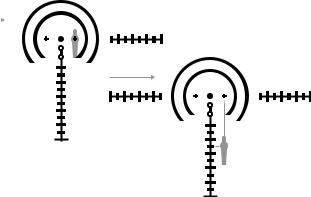
5 MOA left, you will be using the small“+” mark to the right of the center dot as your aiming point (Fig. 4-6). |
|
|
|
|
|
|
|
|
|
|
|
|
|
|
|
|
If you are using the reticle for elevation correction as well as for wind hold, you can establish an aiming point by refer- |
|
|
|
|
|
|
|
|
|
|
|
|
|
|
|
|
encing both the proper vertical wire circle or hashmark and horizontal reference points, and then visualize the target |
|
|
|
|
|
|
|
|
|
|
|
|
|
|
|
|
placement where these points would intersect in the lower right quadrant of the reticle, as shown (Fig. 4-7). |
|
|
|
|
|
|
|
|
|
|
|
|
|
|
|
WIND
Fig. 4-6
Fig. 4-7
24
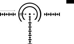
Using SPEEDFORCE for Moving Target Leads
Moving target leads are very similar to wind holds, although typically much more difficult to master. Instead of“holding into the wind,” you will be“holding in front of the target” (Fig. 4-8). There are various methods to mathematically calculate the target lead (such as multiplying the bullet flight time to your target distance by the speed of the target) to determine the lead as it applies to the various reticle subtend points, and then choosing the correct hold point.
En
TARGET
MOVING
Fig. 4-8
25
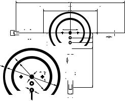
|
Reticle Subtension Chart for SPEEDFORCE |
|
|
|
|
|
|
|
|
|
|
|
|
|
|||||||||||||||||||||||||||
En |
|
|
|
|
|
|
|
|
|
|
|
|
|
||||||||||||||||||||||||||||
4× @ 100 yd. |
|
|
|
|
|
|
|
|
|
|
|
|
|
|
|
|
|
|
|
|
|
|
|
||||||||||||||||||
|
|
|
|
|
|
|
|
|
|
|
|
|
|
|
|
|
|
|
|
|
|
|
|
||||||||||||||||||
|
|
|
|
|
|
|
|
|
L |
|
|
|
|
|
|
|
|
|
|
|
L |
|
|
|
|
|
|||||||||||||||
|
|
|
|
|
|
|
|
|
|
|
|
|
|
|
|
|
K |
|
|
|
|
|
|
|
|
|
K |
|
|
|
|
|
|
|
|
|
|
|
|
|
|
|
|
|
|
|
|
|
|
|
|
|
|
|
|
|
|
|
J |
|
|
|
|
|
|
|
|
|
J |
|
|
|
|
|
|
|
|
|
|
|
|
|
|
|
|
|
|
|
|
Q |
|
|
|
|
|
|
|
|
|
|
I |
|
|
|
|
|
|
|
|
|
F |
|
|
|
|
|
|||||||||
|
R A |
|
|
|
|
|
|
|
|
|
|
|
|
|
O |
|
|
|
|
|
|
|
|
|
|
|
M |
|
|
|
|
|
|
|
|
|
|
|
|
|
|
|
|
|
|
|
|
|
|
|
|
|
|
|
|
|
|
|
|
|
|
|
|
|
|
|
|
|
|
|
F |
|
|
|
|
|
|||||||
|
|
|
|
|
|
|
H |
|
|
|
|
|
|
|
|
|
|
N |
|
|
|
|
|
|
|
|
|
|
|
|
|
||||||||||
|
|
|
|
|
|
|
|
|
|
|
|
|
|
|
|
|
|
|
|
|
|
|
|||||||||||||||||||
|
|
|
|
|
|
|
|
|
|
|
|
|
|
|
P |
|
|
|
F |
|
|
|
|
|
|
|
I |
|
|
|
|
|
|
|
|
|
|
|
|
|
|
|
|
|
|
|
|
|
|
|
|
|
|
|
|
|
|
|
|
|
|
|
|
|
|
|
|
|
|
|
|
|
|
|
|
|
|
||||||
|
|
D |
|
|
|
|
|
|
|
|
|
|
|
|
|
|
|
|
|
|
|
|
|
||||||||||||||||||
|
|
|
|
|
|
|
|
|
|
|
|
|
|
|
|
|
|
|
|
|
|
|
|
||||||||||||||||||
|
|
|
|
|
|
|
|
|
|
|
|
|
|
|
|
|
|
|
|
|
|
|
|
||||||||||||||||||
|
|
|
F |
|
|
|
|
|
|
|
|
|
|
|
|
|
|
|
|
|
|
|
|
|
|||||||||||||||||
|
D |
|
|
|
|
|
|
|
|
|
|
|
|
|
|
|
|
|
|
|
|
|
|
||||||||||||||||||
|
|
|
|
|
|
|
|
|
|
|
|
|
|
|
|
|
|
|
|
|
|
|
|
||||||||||||||||||
|
|
|
|
|
|
|
|
|
|
|
|
|
|
|
|
|
|
|
|
|
|
|
|
||||||||||||||||||
|
|
C B A F |
|
|
|
|
|
|
|
H |
|
|
|
|
|
|
|
|
|
|
|
|
|
||||||||||||||||||
|
|
|
|
|
|
|
|
|
|
|
|
|
|
|
|
|
|
|
|
|
|
||||||||||||||||||||
|
|
|
|
|
|
|
|
|
|
|
|
|
|
|
|
|
|
|
|
|
|
|
|
|
|
|
|
|
|
|
|
|
|
|
|
|
|
|
|||
|
|
|
|
|
|
|
|
|
|
|
|
|
|
|
|
|
|
|
|
Q |
|
|
|
|
|
|
|
|
|
|
|
|
|
|
|
|
|
|
|||
|
|
|
|
|
|
|
|
|
|
|
|
|
|
|
E |
|
|
|
|
|
|
|
|
|
|
|
|
|
|
|
|
|
|
|
|
|
|
||||
|
|
|
|
|
|
|
|
|
|
|
|
|
|
|
|
|
|
|
|
|
|
|
|
|
|
|
|
|
|
|
|
|
|
|
|
|
|
||||
|
|
|
|
|
|
|
|
|
|
|
|
|
|
|
|
|
|
|
|
|
|
|
|
|
|
|
|
L |
|
|
|
|
|
|
|
|
|
|
|
|
|
|
|
|
|
A |
|
|
|
|
|
|
|
|
|
|
|
|
|
|
|
|
|
|
|
|
|
|
|
|
|
|
|
|
|
|
|||||||
|
|
|
|
|
|
|
D |
|
|
A |
|
|
|
|
|
|
|
|
|
|
|
|
|
|
|||||||||||||||||
|
|
|
|
|
|
|
|
|
R |
|
|
|
|
|
|
|
|
|
|
|
|
|
|
|
|
||||||||||||||||
|
|
|
|
|
|
|
|
|
|
|
|
|
|
|
|
|
|
|
|
|
|
|
|
|
|
|
|
|
|
|
|
|
|
|
|||||||
|
|
|
|
|
|
|
|
|
|
|
|
|
|
|
|
|
|
|
|
|
G |
|
|
|
|
|
|
|
|
|
|
|
|
|
|
|
|||||
Letters A to R in the diagram above refer to the reticle subtensions of units A to R shown on the table to the right.
|
|
Model |
BLACK FORCE1000 1-4×24 IL SPEEDFORCE |
Reticle |
|
SPEEDFORCE |
|
Maginification (×) |
4 |
||
|
|
Unit |
MOA |
|
|
A |
2.0 |
|
|
B |
17.0 |
|
|
C |
25.0 |
|
|
D |
1.0 |
|
|
E |
1.5 |
| <![if ! IE]> <![endif]>yd. |
|
F |
0.5 |
| <![if ! IE]> <![endif]>100 |
|
G |
4.0 |
| <![if ! IE]> <![endif]>@ |
|
H |
2.5 |
| <![if ! IE]> <![endif]>subtensions |
|
||
|
I |
10.0 |
|
|
|
J |
17.5 |
| <![if ! IE]> <![endif]>Reticle |
|
K |
20.0 |
|
L |
35.0 |
|
|
|
||
|
|
M |
3.2 |
|
|
N |
6.3 |
|
|
O |
6.5 |
|
|
P |
8.5 |
|
|
Q |
5.0 |
|
|
R |
3.0 |
26

X-MOA Reticle |
|
|
|
|
|
|
|
|
|
|
|
|
|
|
|
|
|
|
|
|
|
|
|
|
|
|
|
|
|
|
|
|
|
|
En |
||
Nikon’s X-MOA reticle (Fig. 4-9) presents the shooter with a clean and visually simple, yet highly functional and advanced tool for estimating range, maintaining holdovers or |
|
|
|
|
|
|
|
|
|
|
|
|
|
|||||
|
|
|
|
|
|
|
|
|
|
|
|
|
|
|||||
dialing elevation come ups and compensating for wind. An advantage of using the X-MOA reticle is that it can be applied to virtually any shooting application regardless of caliber |
|
|
|
|
|
|
|
|
|
|
|
|
|
|
||||
|
|
|
|
|
|
|
|
|
|
|
|
|
|
|||||
or ballistic performance, and when paired with the BLACK X1000 Riflescope, provides shooters with the tools necessary for long-range shooting precision. |
|
|
|
|
|
|
|
|
|
|
|
|
|
|
||||
|
|
|
|
|
|
|
|
|
|
|
|
|
|
|||||
The X-MOA reticle was engineered using 2-MOA-thick outer posts at 3, 6, 9 and 12 o’clock to draw the eye toward the reticle that“free-floats” 6 MOA inside each post. To maintain |
|
|
|
|
|
|
|
|
|
|
|
|
|
|
||||
|
|
|
|
|
|
|
|
|
|
|
|
|
|
|||||
an uncluttered appearance, the reticle utilizes 1 MOA hash marks spaced at 2 MOA, with larger 4 MOA“reference hashes” at 10 and 20 MOA on each horizontal and vertical wire. |
|
|
|
|
|
|
|
|
|
|
|
|
|
|
|
|
||
|
|
|
|
|
|
|
|
|
|
|
|
|
|
|||||
The BLACK X1000 has the X-MOA reticle placed in the riflescope’s second focal plane, so all holdover corrections, ranging and other measurements using the indicated reticle |
|
|
|
|
|
|
|
|
|
|
|
|
|
|
||||
|
|
|
|
|
|
|
|
|
|
|
|
|
|
|||||
subtensions should be done at the following magnifications: |
|
|
|
|
|
|
|
|
|
|
|
|
|
|
||||
|
|
|
|
|
|
|
|
|
|
|
|
|
|
|||||
BLACK X1000 |
4-16×50SF X-MOA = 16× |
|
|
|
|
|
|
|
|
|
|
|
|
|
|
|||
BLACK X1000 |
4-16×50SF IL X-MOA = 16× |
Fig. 4-9 |
||||||||||||||||
BLACK X1000 |
6-24×50SF IL X-MOA = 18× |
|||||||||||||||||
|
|
|
|
|
|
|
|
|
|
|
|
|
|
|||||
MOA Subtensions
A minute of angle (MOA) is 1/60th of a degree at a certain distance. Thus, MOA cannot be effectively used without also knowing the target distance. The true value of a minute of angle is 1.047 inches per hundred yards of distance. Considering this, most shooters will find it is acceptable to round one MOA to 1” per 100 yards for most applications: 1” at 100 yards, 2” at 200 yards, and so on. For a totally accurate measurement however, you would then subtract 4.7% from the calculation, which is increasingly important the further the target range.
27

|
Using X-MOA for Ranging |
|
|
|
|
|
|
|
En |
|
|
|
|
|
|
|
|
To determine range with minute of angle, divide the target’s known size in inches by the MOA measurement from the reticle (at the riflescope’s highest magnification) and then |
|
|
|
|
|
|
||
|
|
|
|
|
|
|
||
|
multiply by 100. The result is the distance in yards to the measured object. |
|
|
|
|
|
|
|
|
Target size (inches) ÷ Target size in reticle (MOA) × 100 = Distance (yards) to Target |
|
|
|
|
|
|
|
|
For example if we know that the bullseye is 12” in diameter and it measures as 6 MOA at max zoom (Fig. 4-10), the equation would be: |
|
|
|
|
|
|
|
|
12 ÷ 6 × 100 = 200 yards to the target |
|
|
|
|
|
|
|
|
This method can be used to create a cheat sheet if you know your target size will be constant, by calculating distance at several MOA measurements. For example with 12” targets: |
|
|
|
|
|
|
|
|
|
|
|
|
|
|
||
|
|
|
|
|
|
|
||
|
2 MOA = 600 Yards |
3 MOA = 400 Yards |
|
|
|
|
|
|
|
|
|
|
|
|
|
||
|
|
|
|
|
|
|
||
|
4 MOA = 300 Yards |
5 MOA = 240 Yards |
|
|
|
|
|
|
|
|
|
|
|
|
|
||
|
6 MOA = 200 Yards |
8 MOA = 150 Yards |
|
|
|
|
|
|
|
|
|
|
|
|
|
||
|
10 MOA (Large line on reticle) = 120 Yards |
|
|
|
|
|
|
|
|
Using this method it can become quite easy to quickly estimate target range and then apply holdover. When combined with a laser rangefinder, the equation can be manipulated to |
|
|
Fig. 4-10 |
||||
|
determine target size. It is important to remember a few rules for the application of this: |
|
|
|||||
|
|
|
|
|
|
|
||
•You must know the size of the target to estimate range or know the distance to estimate size.
•This only works when the optic is at maximum magnification.
28

Using X-MOA for Wind Hold
Using the X-MOA reticle for windage correction is much faster than using the riflescope’s windage adjustment turret for both the initial shot and any follow-up shots. When adjusting for wind hold using the reticle, you can use the various hashmarks on the reticle’s horizontal wire like a ruler to reference your specified point for aiming into the wind. For example, if the wind speed value has you holding 4 MOA left, you will be using the second small hash mark to the right of the crosshair as your aiming point (Fig. 4-11).
If you are using the reticle for elevation correction as well as for wind hold, you can establish an aiming point by referencing both the proper vertical and horizontal hashmarks and then visualize the target placement where the hashmarks would intersect in the lower right quadrant of the reticle, as shown (Fig. 4-12).
En
WIND |
WIND |
Fig. 4-11 |
Fig. 4-12 |
29

|
Using X-MOA for Moving Target Leads |
|
En |
||
Moving target leads are very similar to wind holds, although typically much more difficult to master. Instead of“holding into the wind”, you will be“holding in front |
||
|
||
|
of the target” (Fig. 4-13). There are various methods to mathematically calculate the target lead (such as multiplying the bullet flight time to your target distance |
|
|
by the speed the target) to determine the lead as it applies to the various reticle subtend points and then choosing the correct hold point. |
TARGET
MOVING
Fig. 4-13
30
 Loading...