


INC
JAA80051-R.3741.A
AF-S DX Nikkor
16-85mm f/3.5-5.6G ED VR
JAA80051
REPAIR MANUAL
Copyright 2008 by Nikon Corporation. All Rights Reserved.
!!
Printed in Japan February 2008

INC
JAA80051-R.3741.A
Before Disassembly / Reassembly / Adjustment
This lens will require optical lens alignment after assembly, in case the 4th lens-group unit is removed.
At repair service facilities, therefore, where this alignment work can not be performed, do NOT remove the 4th lens-group unit.
This lens also has the VR (vibration-reduction) unit mounted in order to correct camera shake.
To keep the accuracy of this function for stabilizing the image, in case VR unit or the main PCB is replaced, be sure to make the VR adjustment by using the VR lens adjustment equipment (J15380).
Except for disassembling the above components, the VR adjustment is NOT necessary, but check VR operations by attaching this lens to the camera.
At repair service facilities where the "VR lens adjustment equipment" is not prepared, do NOT disassemble NOR repair the products of the above cases.
Caution:
When disassembling/(re)assembling, be sure to use the conductive mat (J5033) and wrist strap (J5033-5) for static protection of electrical parts.
When disassembling, make sure to memorize the processing state of wires, screws to be fixed and their types, etc.
Because prototypes are used for "1. Disassembly" and "2. Assembly/Adjustment", they may differ from the actual products in forms, etc.
Because pictures are processed by a special method, they may differ from the actual ones in texture.
Points to notice for Lead-free solder products
Lead-free solder is used for this product.
For soldering work, the special solder and soldering iron are required.
Do NOT mix up lead-free solder with traditional solder.
Use the special soldering iron respectively for lead-free solder and lead solder. They cannot be used in common.
- 1 AF-S DX 16-85/3.5-5.6G VR -
INC
JAA80051-R.3741.A
1.Disassembly
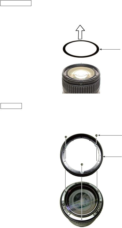
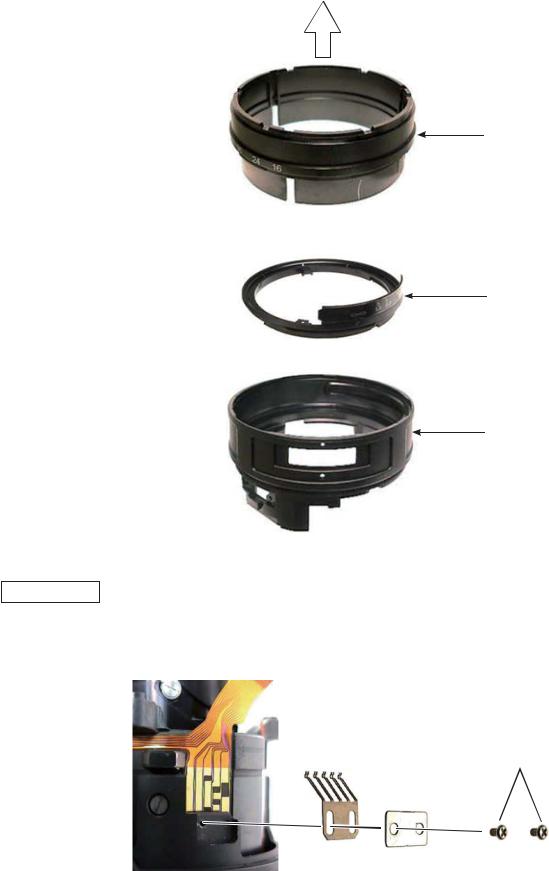
Protection sheet
Peel off the protection sheet (#60) by inserting tweezers from the outside into the cutout of attaching face as below.
#60
Filter ring
Take out the three screws (#119) and remove the filter ring (#35).
#119×3
#35
- 2 AF-S DX 16-85/3.5-5.6G VR -
INC
JAA80051-R.3741.A
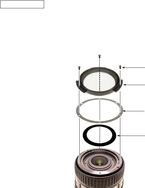
1st lens group unit
Set the zoom ring to WIDE.
Take out the three screws (#120) and remove the 1st lens-G unit (B2041) and washer (#133).Peel off the sheet (#62).
#120×3
B2041
#133
#62
- 3 AF-S DX 16-85/3.5-5.6G VR -
INC
JAA80051-R.3741.A
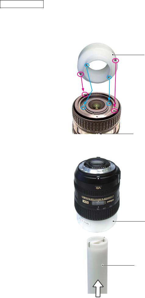
2nd lens group unit
Set the zoom ring to WIDE-end.
Set the focus index (#49) to "∞" position.
Mount the fixing tool for 2nd lens-G ( J11356) by fitting its protrusions in the holes of the 1st lens-G cam ring (#38) and the 2nd lens-G cam ring (#25).
J11356
Index
Insert the wrench for the 2nd lens-G ( J11358) into the 2nd lens-group unit (B2043).
J11356
J11358
- 4 AF-S DX 16-85/3.5-5.6G VR -
INC
JAA80051-R.3741.A
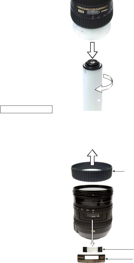
Turn the wrench for 2nd lens-G ( J11358) counterclockwise, and remove the 2nd lens-group unit (B2043).
 J11356
 B2043
B2043
 J11358
Name plate/Focus window
Remove the rubber ring (#37).
Remove the name plate (#75) and focus window (#76).
Caution: Remove the name plate (#75) and focus window (#76) ONLY when they must be replaced because of defects, etc.
#37
#76
#75
- 5 AF-S DX 16-85/3.5-5.6G VR -
INC
JAA80051-R.3741.A
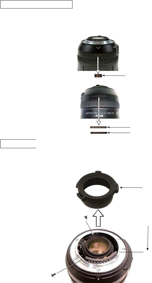
VR name plate / Serial No.label
Remove VR name plate (#69) and serial number label (#168 or #169).
Caution: Remove VR name plate (#69) and serial number label (#168 or #169) ONLY when they must be replaced because of defects, etc.
#69
#169
#168
Rear cover ring
Take out the three screws (#118) and remove the rear cover ring (#39).
#39
#118×3
- 6 AF-S DX 16-85/3.5-5.6G VR -
INC
JAA80051-R.3741.A
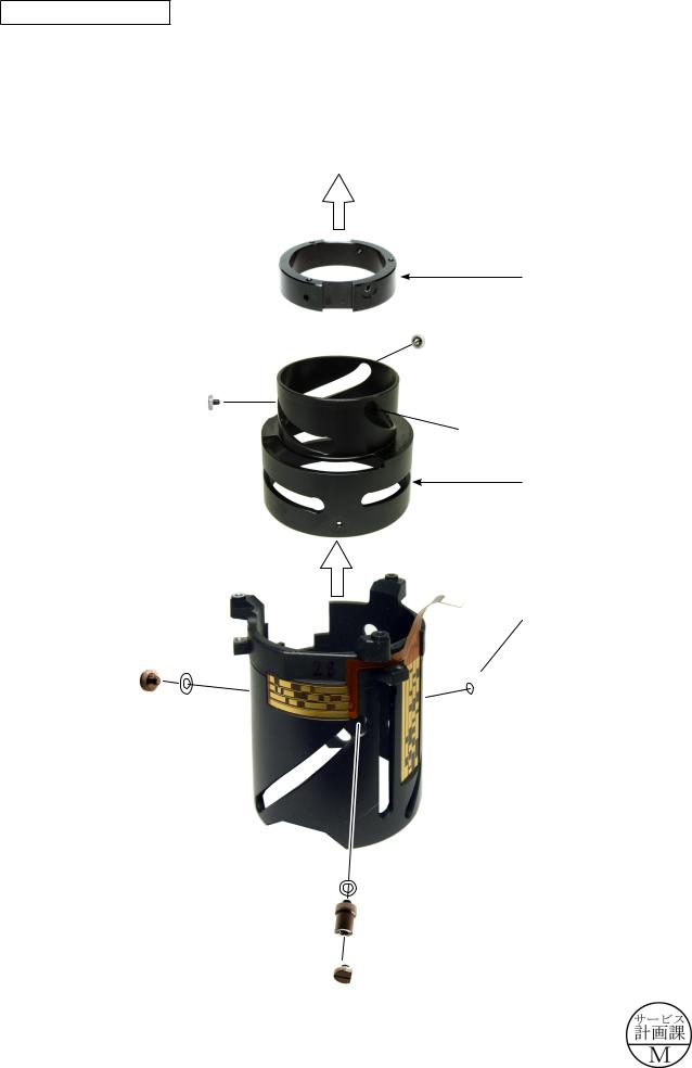
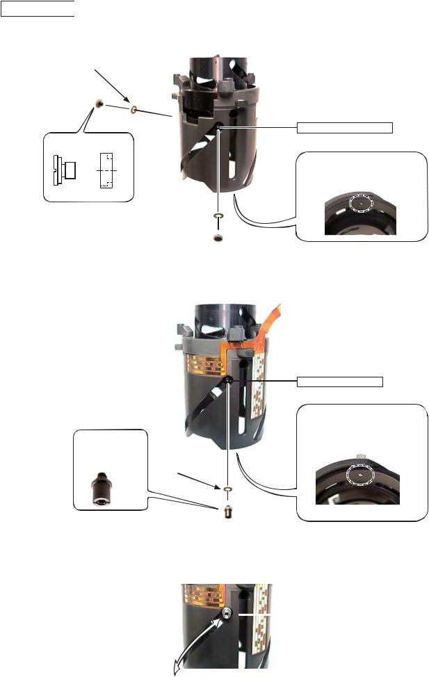
4th lens-group unit
Caution: When the 4th lens-group unit is removed, the lens alignment work will be necessary after assembly. Therefore, at service facilities where the alignment work can not be performed, do NOT remove the 4th lens-group unit.
Set the zoom ring to WIDE.
Peel off the sheet (#70) from the 4th lens-G unit (B2046).
Take out the three screws (#124), and remove the 4th lens group unit (B2046) and washer (#139).
Top view
Caution
Lens alignment is made for the 4th lens-G unit, so do NOT touch the three screws (#125).
#70
#124×3
B2046
#139
Take out the two screws (#117).
#117×2
- 7 AF-S DX 16-85/3.5-5.6G VR -
INC
JAA80051-R.3741.A
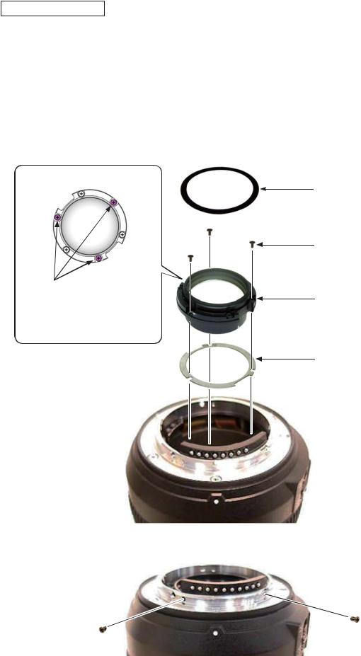
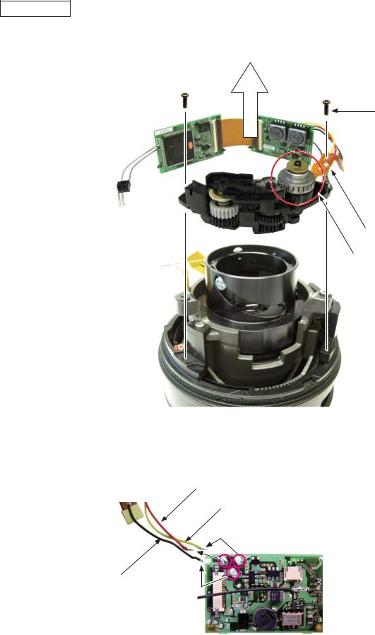
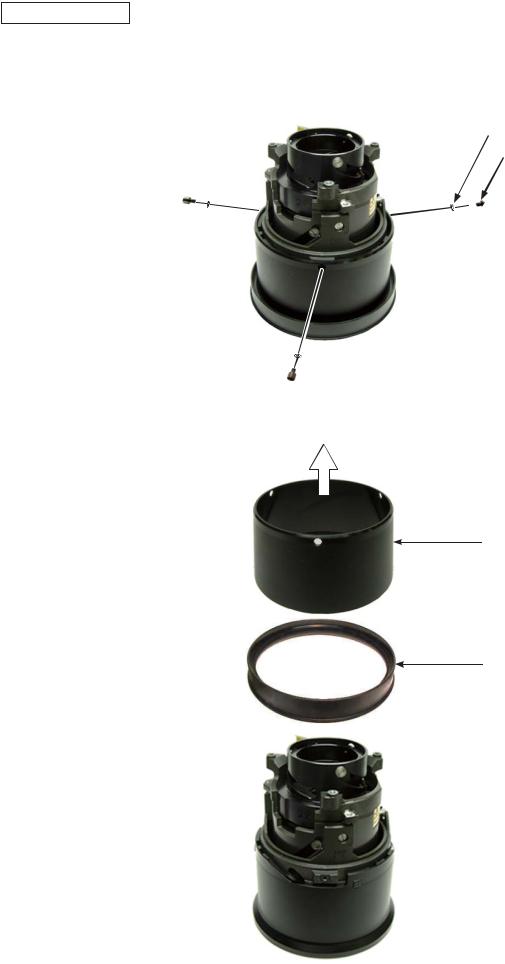
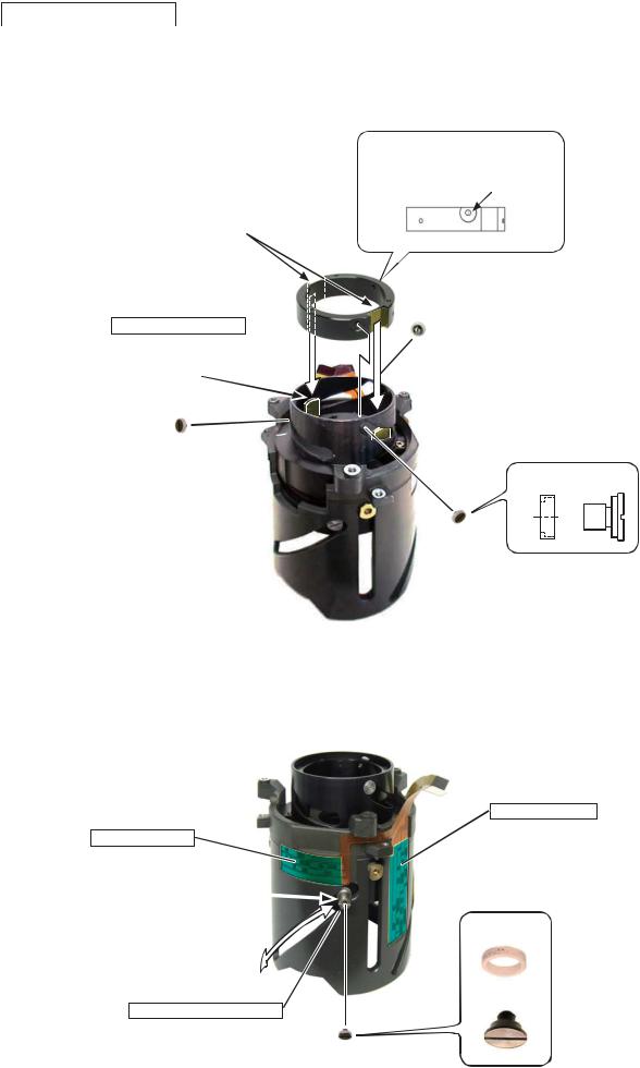
Bayonet mount unit
Take out the three screws (#115) and the one screw (#114), and remove the bayonet mount unit (B30).
#115×3
#114
B30
B29
Caution:
Do NOT remove the bayonet mount unit (B30) and the rear fixed tube unit (B29) together.
The main PCB is connected by the FPC of the rear fixed tube (B29), so do NOT pull the FPC by force. Otherwise the FPC will be damaged.
Remove the washer (#79).
 #79
#79
- 8 AF-S DX 16-85/3.5-5.6G VR -
INC
JAA80051-R.3741.A
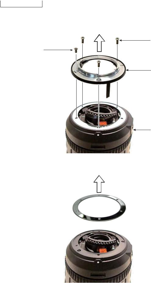
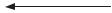
Rear fixed tube unit
Disconnect the FPC of the rear fixed tube unit (B29) from the connector of the main PCB (B1001).Remove the rear fixed tube unit (B29).
 B29
B29
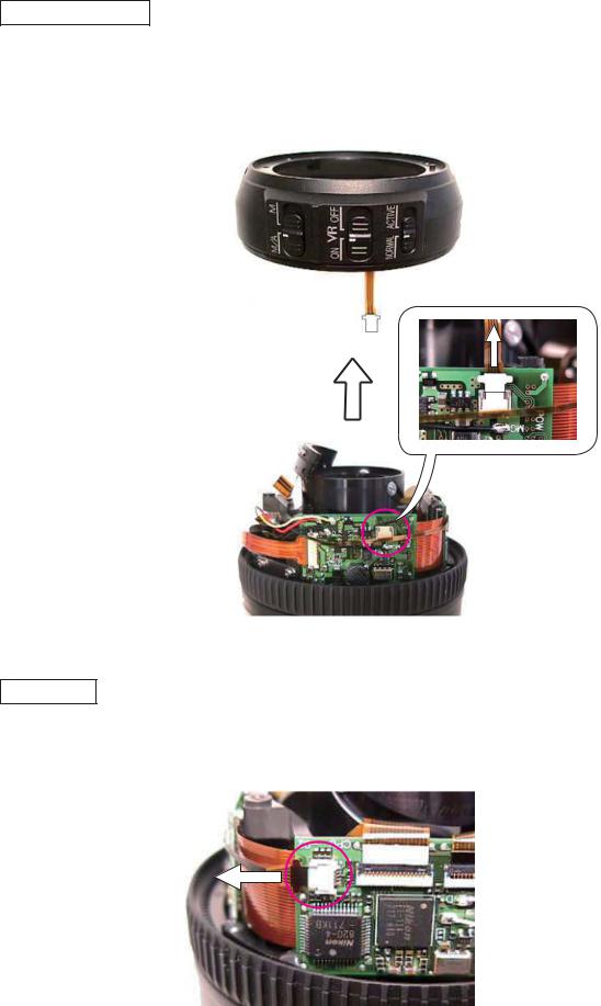
Main PCB
Disconnect the FPC of GMR unit (#1011) from the connector of the main PCB (B1001).
- 9 AF-S DX 16-85/3.5-5.6G VR -
INC
JAA80051-R.3741.A
Disconnect the connection-FPC (#1001) from the connector of the main PCB (B1001). Caution:
Be sure to release the locks of the connector before pulling the FPCs. |
#1001 |
|
Release lock here.
Disconnect the FPC of the contact unit (B1007) from the connector of the main PCB (B1001).
B1007
Caution:
Be sure to release the locks of the connector before pulling the FPCs.
MF ring
Remove MF ring (#26).
#26
- 10 AF-S DX 16-85/3.5-5.6G VR -

INC
JAA80051-R.3741.A
Lug plate unit
Take out the screw (#123), and remove the lug plate unit (B1028).
B1028
#123
MF brush unit
Take out the screw (#587),and remove MF brush unit (#2533) from SWM unit.
#587
#2533
- 11 AF-S DX 16-85/3.5-5.6G VR -
INC
JAA80051-R.3741.A
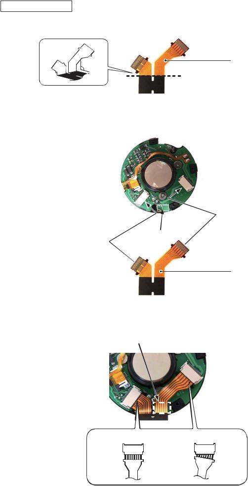
SWM unit
Take out the two screws (#145), and remove SWM unit and main PCB (B1001). Caution: Do NOT touch "A" area.
#145×2
Back side has doublestick tape attached
"A" area
Remove the three lead wires of SWM unit from the main PCB (B1001).
Lead wire (red) (#1029)
Lead wire (yellow (#1030)
Lead wire (black) (#1031)
- 12 AF-S DX 16-85/3.5-5.6G VR -
INC
JAA80051-R.3741.A
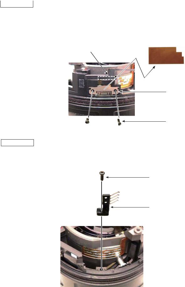
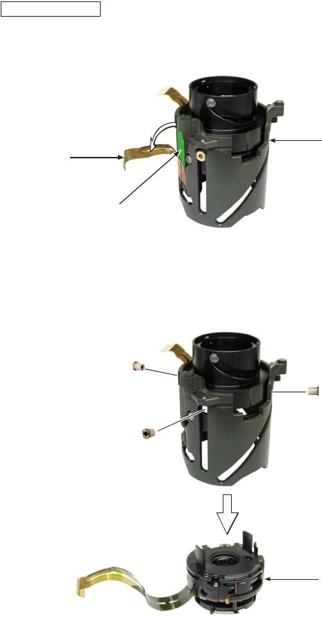
GMR sensor
Peel off the tape (#138).
Take out the two screws (#91). Remove the FPC from the double-stick tape and remove GMR sensor (#1011).
#138
Double-stick tape
#1011
#91×2
Focus brush
Turn the focus brush in the direction of CLOSE.
Take out the screw (#145), and remove the focus brush (B105).
#145
B105
- 13 AF-S DX 16-85/3.5-5.6G VR -
INC
JAA80051-R.3741.A
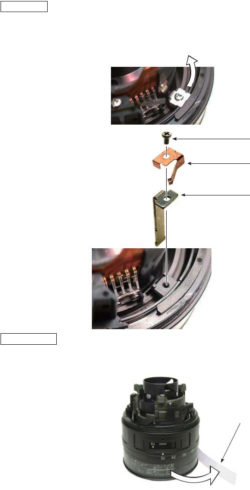
Focus key
Move the key (#54) in the direction of the arrow.
Take out the screw (#122), and remove the plate spring (#157) and focus key (#54).
#122
#157
#54
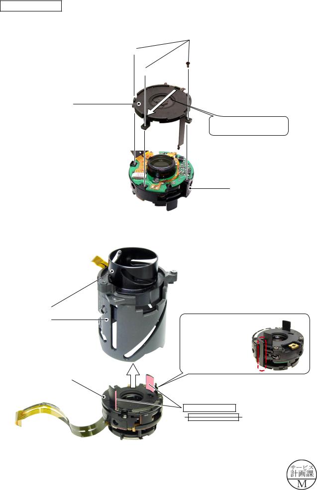
Fixed ring unit
Peel off the tape (#135).
#135
- 14 AF-S DX 16-85/3.5-5.6G VR -
INC
JAA80051-R.3741.A
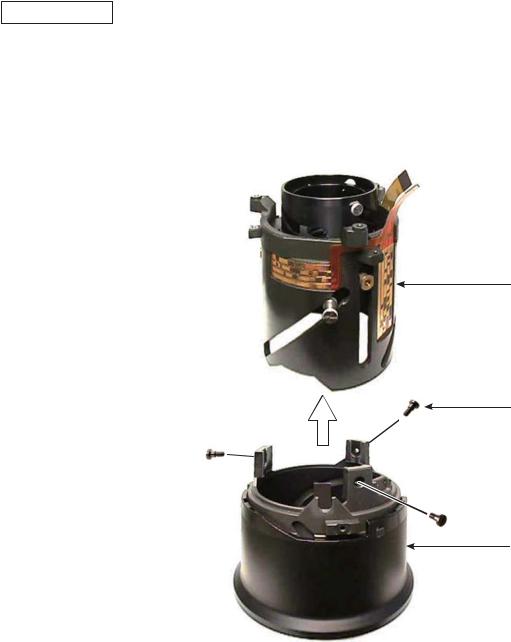
Fixed ring unit (continued)
(Revision)
Take out the two screws (#123),and remove the zoom index ring the fixed ring unit.
#123×2
(Revision)
 Zoom index ring Fixed ring unit
Take out the screw (#144).
Remove the zoom control key unit (B140) from the fixed ring unit.
#144
B140
Changed page × 2 |
- 15 AF-S DX 16-85/3.5-5.6G VR - |
March 13 2008 |
INC
JAA80051-R.3741.A
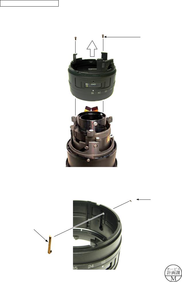
Remove the zoom ring unit (B27) and gear unit (B40) from the fixed ring (#55).
B27
B40
#55
Zoom brush
Take out the two screws (#109), and remove the reinforcing plate (#106) and zoom brush (#104).
#104
#109×2
#106
- 16 AF-S DX 16-85/3.5-5.6G VR -
INC
JAA80051-R.3741.A
Cover ring unit
Take out the three screws (#110).
Take out the screws carefully because sometimes the adjustment washer (#107) is put.
#107 (Adjustment washer) #110×3
Remove the cover ring unit (B36) and support ring unit (B101).
B36
B101
- 17 AF-S DX 16-85/3.5-5.6G VR -
INC
JAA80051-R.3741.A
Fixed tube
Take out the three screws (#67), and remove the fixed tube (#50) from the 2nd lens-G straight ring (B52).
#50
#67×3
B52
- 18 AF-S DX 16-85/3.5-5.6G VR -
INC
JAA80051-R.3741.A
VR unit-assembly
Remove the connection-FPC (#1001) from the double-stick tape adhered to the fixed tube (#50).
#50
#1001
Double-stick tape
Remove the three roller units (B68), and detach VR unit-assembly (B2306).
B68×3
B2306
- 19 AF-S DX 16-85/3.5-5.6G VR -
INC
JAA80051-R.3741.A
Aperture unit
Take out the three screws (#56), and remove the aperture unit (B34).
Remove the connection-FPC (#1001) from the double-stick tape, and disconnect it from the connector of VR unit in numeric order from to .
#1001 |
|
#56×3 |
|
Double-stick
tape
B34

- 20 AF-S DX 16-85/3.5-5.6G VR -
INC
JAA80051-R.3741.A
4th lens-G sliding ring
Remove the three roller units (B81), and remove the 4th lens-G sliding ring (#48) from the 3-4 lens-G cam ring (#24).
(Addition)
Remove the two roller units (B83), roller unit (B99), roller unit (B102) and three washers (#82), then remove the 3-4 lens-G cam ring (#24) from the fixed tube (#50).
#48

 B81×3
B81×3
#24
#82×3


 B83×2
B83×2
 #50
#50
B99
(Addition)
B102
Changed page × 2 |
- 21 AF-S DX 16-85/3.5-5.6G VR - |
March 13 2008 |
INC
JAA80051-R.3741.A
2. Assembly / Adjustment
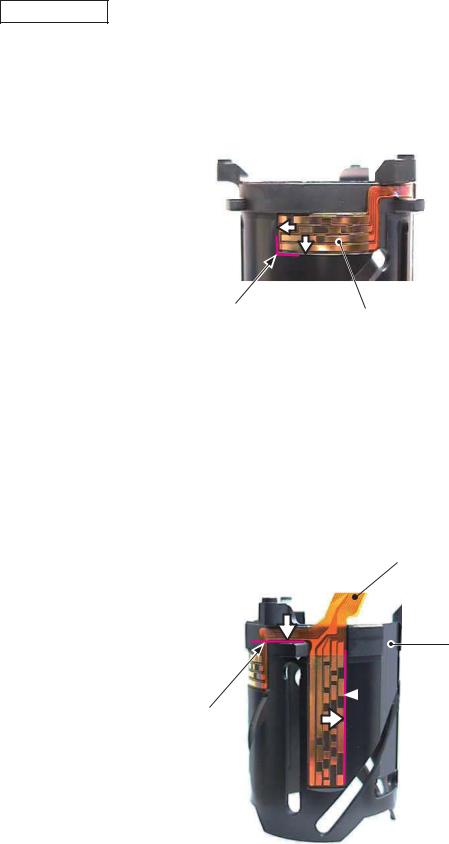
Encoder FPC
Place the encoder-FPC (#1006) on the fixed tube (#50) based on the below reference position, and attach it by pressing in the direction of the arrow for positioning.
 #50
#50
Reference position |
#1006 |
Place the encoder-FPC (#1006) on the fixed tube (#50) based on the below reference position each, and attach it by pressing in the direction of the arrow for positioning.
#1006
#50
 Reference position
Reference position
- 1 AF-S DX 16-85/3.5-5.6G VR -
INC
JAA80051-R.3741.A
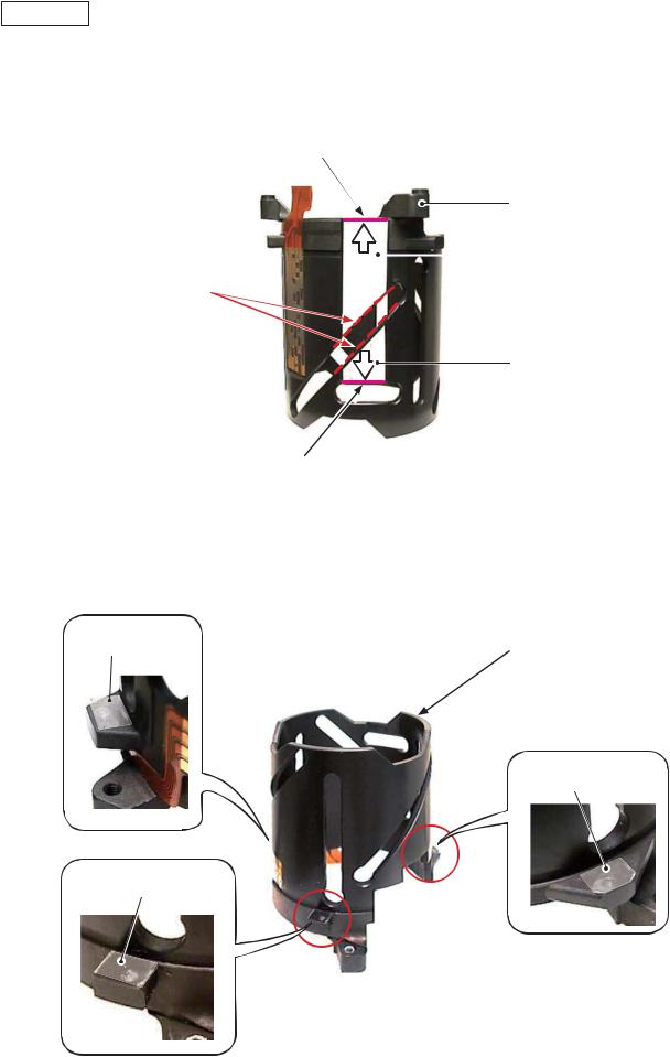
Tape
Place the two pieces of the double-stick tape (#149 and #150) on the fixed tube (#50) based on the below reference position each, and attach it by pressing in the direction of the arrow for positioning.
|
Reference position |
||
|
#50 |
||
Caution: |
|
|
#150 |
|
|||
When the tape is attached, it must NOT cross the dot lines which show the edges of the cam groove.
#149
Reference position
Adhere the three pieces of the tape to cover the screw holes.
TA-0012 |
|
5×3.5 |
#50 |
TA-0012 5×3.5
TA-0012 5×3.5
- 2 AF-S DX 16-85/3.5-5.6G VR -
Fixed tube
Assemble the 3-4 lens-G cam ring (#24) into the fixed tube (#50).
#24
(Revision)
Grease: MZ-400EL
Grease: MZ-400T
Apply to the overall sliding surfaces of the three cam grooves.
(Revision)
Grease: MZ-400EL
Grease: MZ-400T
Apply to the overall sliding surfaces of the three cam grooves.
INC
JAA80051-R.3741.A
(Revision)
Grease: MZ-400EL
Grease: MZ-400T
Apply to the overall surface of the inside.
#50
(Revision)
Grease: MZ-400EL
Grease: MZ-400T
Apply to the overall sliding surfaces of the three cam grooves.
(Revision)
Grease: MZ-400EL
Grease: MZ-400T
Apply to the overall surface sliding with [#24].
(Revision)
Grease: MZ-400EL
Grease: MZ-400T
Apply to the overall sliding surfaces of the three lead grooves.
Changed page × 6 |
- AF-S DX 16-85/3.5-5.6G VR - |
March 13 2008 |
INC
JAA80051-R.3741.A
Roller unit
Mount the 3-4 lens-G cam ring (#24) on the fixed tube (#50), and secure them with the two roller units (B83) and two washers (#82).
#82×2
B83×2
#83×2 #84×2
 #24
#24
 #50
#50
Adhesive: Lockend (R)
Screw hole ×2
If the adhesive of [#24] is squeezed out to the inside, wipe it out.
Attach the roller unit (B99) and washer (#82) to the 3-4 lens-G ring (#24).
#24
#50
 #94
#94
#82
#99
Adhesive: Lockend (R)
Screw hole
If the adhesive of [#24] is squeezed out to the inside, wipe it out.
B99
Check the operations by sliding the roller unit (B99).
 B99
B99
- 4 AF-S DX 16-85/3.5-5.6G VR -
INC
JAA80051-R.3741.A
VR unit-assembly
Make a valley-fold along the dotted line of the connection-FPC (#1108).
90° |
#1108 |
|
|
|
Valley-fold |
Peel off the backing paper of the double-stick tape.
Connect the connection-FPC (#1108) to the connector of VR unit-assembly (B2308) in numeric order fromto .
 B2308
B2308
Double-stick tape
#1108
Push the double-stick tape from above with the fingers to fixate the connection-FPC (#1108)
Double-stick tape
Insert FPC all the way seated in.
Do NOT insert FPC sideways.
- 5 AF-S DX 16-85/3.5-5.6G VR -
INC
JAA80051-R.3741.A
Aperture unit
Position the aperture unit (B34) in the direction of the arrow, and tighten the three screws (#56) in numeric order , , and .
#56×3


B34
Direction of positioning
B2308
Assemble VR unit (B2308) into the 3-4 lens-G cam ring (#24).
#48
#24
Be careful NOT to hold the lever when assembling, in order to prevent deformation.
B2308
(Revision)
Grease: MZ-400EL
Grease: MZ-400T
Apply to the two lateral and inner surfaces of the protrusions.
Changed page × 1 |
- AF-S DX 16-85/3.5-5.6G VR - |
March 13 2008 |

INC
JAA80051-R.3741.A
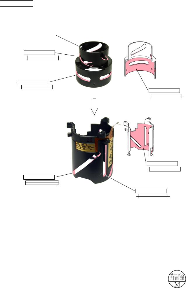
Assemble the fixed tube (#50), 3-4 lens-G cam ring (#24), and VR unit-assembly (B2308) together by using the three roller units (B68).
#68×3 |
#147×3 |
#148×3 |
The head of the roller unit (B68) must be
positioned against the lead groove as below.
B68×3
GOOD
BAD
#1008
 #24
#24
 #50
#50
Through this hole, pass the connection-FPC (#1008) from the inside of the fixed tube (#50) toward the outside.
Peel off the backing papers of the double-stick tapes (#149 and #150) and attach the connection-FPC (#1008).
#1008
Edge line of the cam groove
Attach the FPC based on the refer- |
|
ence position and dot line (edge of |
|
cam groove), being careful of the |
|
corner as shown in the right picture. |
Reference position |
- 7 AF-S DX 16-85/3.5-5.6G VR -
INC
JAA80051-R.3741.A
4th lens-G sliding ring
Mount the 4th lens-G sliding ring (#48) by fitting its two cutouts with the two protrusions of VR unit.Attach the three roller units (B81) to the 4th lens-G sliding ring (#48) through the cam groove of the 3-4
lens-G cam ring (#24) and fasten them.
Be careful of up/downward direction for mounting.
Screw hole
Cutout×2
 #48
#48
Adhesive: Lockend B 
Screw hole ×3
Protrusion×2 of VR unit
 #24
#24
#84×3 #81×3
B81×3
Attach the roller unit (B102) to the roller unit (B99) and fasten it.Check operations by sliding the roller unit (B99).
Grease: PL-22SEL
Pattern surface
Grease: PL-22SEL
Pattern surface
B99
#103
#102
Adhesive: Lockend R Screw hole
B102
- 8 AF-S DX 16-85/3.5-5.6G VR -
 Loading...