


JAA79201-R.3669.A
AF-S DX Nikkor ED
18-55/3.5-5.6G
JAA79201
JAA79251
Silver
Black
REPAIR MANUAL
Copyrigh 2005 by Nikon Corporation. All Rights Reserved.
!!
Printed in Japan May 2005
|
JAA79251-R.3669.A |
Specifications |
|
Type of lens: |
G-type AF-S DX Zoom-Nikkor lens with built-in CPU and Nikon bayonet |
|
mount (Specially designed for use with Nikon digital SLR – Nikon DX |
|
format – cameras) |
Focal length: |
18mm–55mm |
Maximum aperture: |
f/3.5–5.6 |
Lens construction: |
7 elements in 5 groups (1 ED and 1 aspherical lens elements) |
Picture angle: |
76° – 28°50´ |
Focal length scale: |
18, 24, 35, 45, 55mm |
Distance information: Output to camera body |
|
Zoom control: |
Manually via separate zoom ring |
Focusing: |
Autofocus using a Silent Wave Motor; manually via separate focus ring |
Closest focus distance: 0.28m (0.9 ft.) at all zoom settings |
|
Diaphragm: |
Fully automatic |
Aperture range: |
f/3.5 to f/22 (at 18mm), f/5.6 to f/38 (at 55mm) |
Exposure measurement:Via full-aperture method |
|
Attachment size: |
52mm (P = 0.75mm) |
Dimensions: |
Approx. 69mm dia. x 74mm extension from the camera’s lens-mount flange |
Weight: |
Approx. 210g (7.4 oz) |
Specifications and designs are subject to change without any notice or obligation on the part
- M1 AF-S DX 18-55/3.5-5.6G -

Disassembly / Assembly / Adjustment
JAA79201-R.3669.A
Note:
②
When disassembling, make sure to memorize the processing state of wires and FPC. Because prototypes are used for "Disassembly/(Re)assembly/Adjustment", they may differ from the actual products in forms, etc. Because pictures are processed by a special method, they may differ from the actual ones in texture.
Points
to notice for Lead-free solder products
Lead-free solder is used for this product.For soldering work, the special solder and soldering iron are required.
Do NOT mix up lead-free solder with traditional solder.Use the special soldering iron respectively for lead-free solder and lead solder. They cannot be used in common.
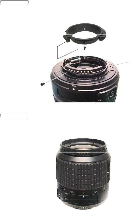
1. Disassembly
Company name ring
The company name ring (#113) is attached with the both-sided adhesive tape.
 #113
#113
Name plate
#68
Note: Detaching the name plate (#68) is NOT necessary EXCEPT replacing it.
- 1 AF-S 18-55/3.5-5.6G -
JAA79201-R.3669.A
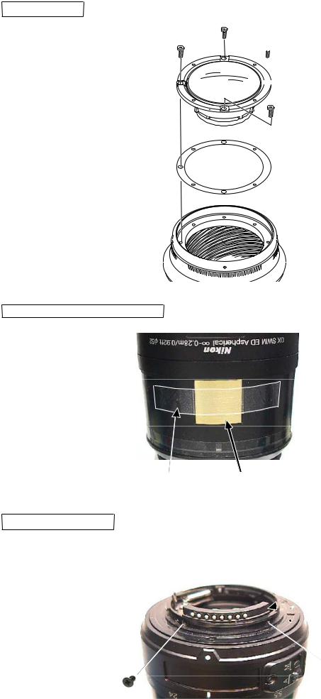
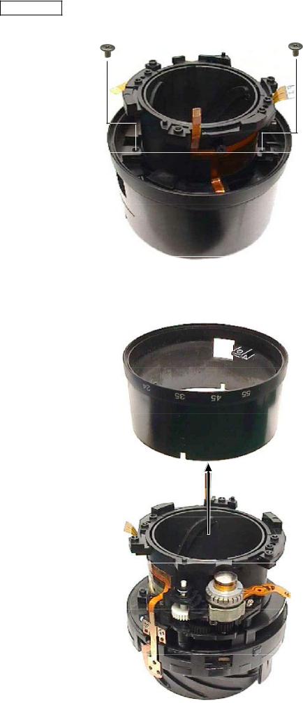
Rear cover ringTake out 3 screws (#91) to remove the rear cover ring (#39).
#39
#B27 
 #91×3
#91×3
Rubber ringRemove the rubber ring (#62).
 #62
#62
- 2 AF-S 18-55/3.5-5.6G -
JAA79201-R.3669.A
1st lens group
 #111×4


 #B1
#B1
 #100A I×n
 #52
#52
Distance brush hole-sealing plate
Polyester tape
#103
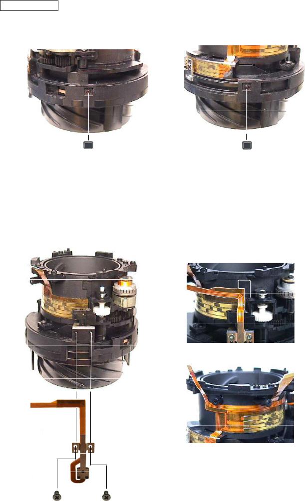
Removal of Contact unitTake out 2 screws (#67) of the contact unit (#B6) that is attached to the bayonet mount unit (#B27).
 #B6
#B6
 #B27
#B27
 #67×2
#67×2
- 3 AF-S 18-55/3.5-5.6G -
JAA79201-R.3669.A
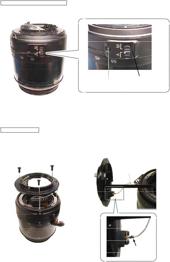
Removal of M/A change-SW unit
Take out the screw (#155) to remove the M/A change-SW unit(#B22).
#B22
 #155
#155
Bayonet mount unitTake out 3 screws (#78) of the bayonet mount unit (#B27) to remove the lead wire (#1131).
#78×3
#1131
#B27
Remove the solder.
- 4 AF-S 18-55/3.5-5.6G -

JAA79201-R.3669.A
Washer
Remove the washers #101A J×n).
#101A J×n
 #1131
#1131
Flare cutter
Release the key part of the flare cutter (#46) from the key-groove of the cam tube, then remove the flare cutter.
Key part

Release the key part from the key-groove.
Set the zoom position to WIDE-end. While pressing the pointed tip of the key inward,
remove the key by turning clockwise.→
#46
#B24
Key-groove of Cam tube
- 5 AF-S 18-55/3.5-5.6G -

JAA79201-R.3669.A
Straight key unit
#86×2 |
#86×2 |
|
#B25B |
#B25A |
2nd lens group
#B24
- 6 AF-S 18-55/3.5-5.6G -

JAA79201-R.3669.A
Rear fixed tube
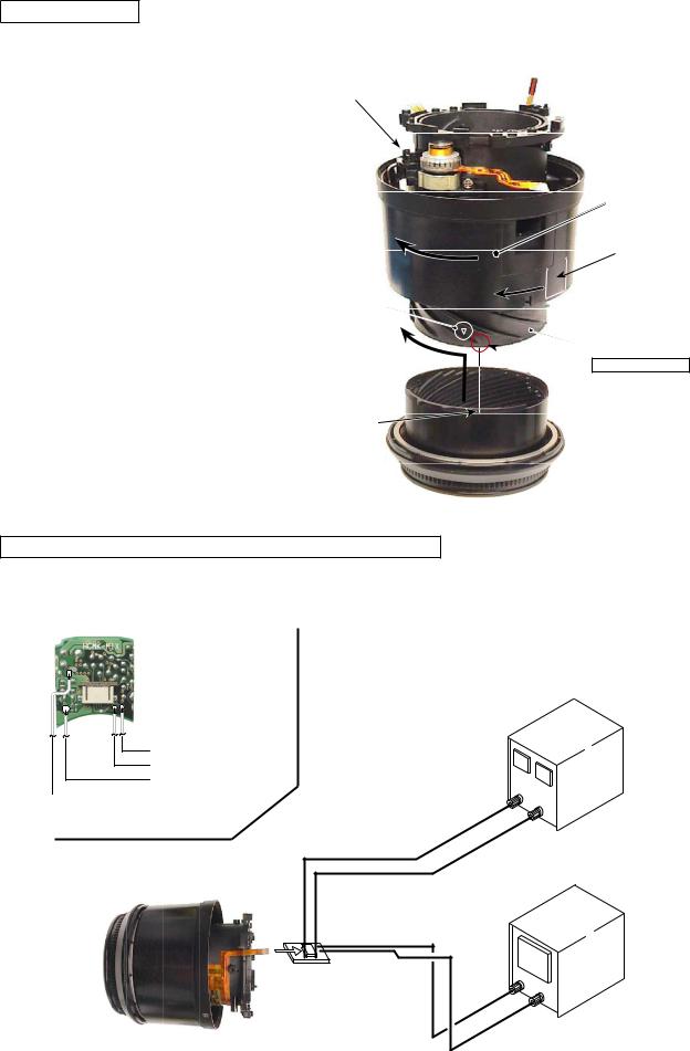
Set the M/A change-SW unit (#B22) to A mode. Detach it from the window of the rear fixed tube (#57) and remove the rear fixed tube.
#57
Note: Do NOT touch "A" part directly with hand. A
#B22 Removal of FPC from Main-PCB unit
Remove the SWM unit (#B501) from the main-PCB unit (#B1001).
#B1001
 #B501
#B501
Remove the contact unit (#B6) and MR unit (#B7) from the connector of the main-PCB unit (#B1001). |
|
#B7 |
#B6 |
#B1001
- 7 AF-S 18-55/3.5-5.6G -
JAA79201-R.3669.A
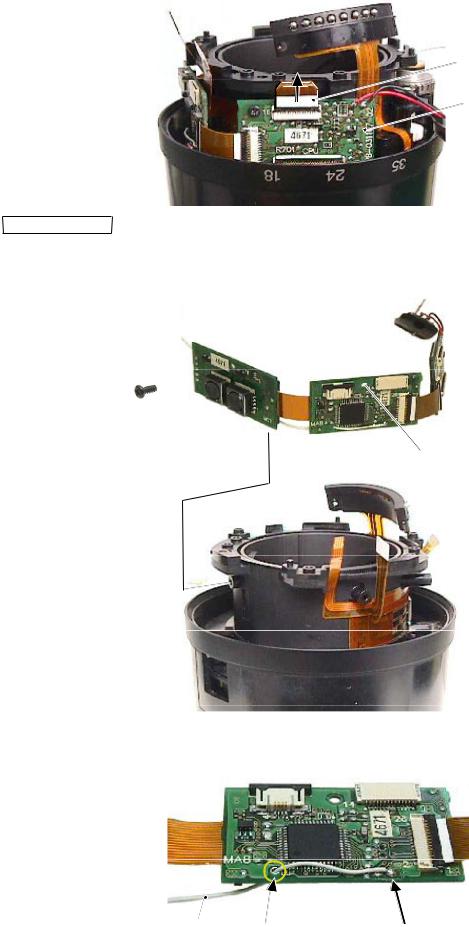
Remove the zoom/distance FPC from the connector of the main-PCB unit (#B1001).
Zoom/distance FPC
#B1001
Main PCB unitRemove the main-PCB unit (#B1001).

 #89 #89
#B1001
 #89
#89
Remove the lead wire (#1131) from the main-PCB unit (#B1001).
#1131 |
Hole |
Remove the solder. |
|
- 8 AF-S 18-55/3.5-5.6G -
JAA79201-R.3669.A
M/A change-SW unit
Remove 2 lead wires of the M/A change-SW unit (#B22) from the main PCB unit (#B1001).
#B1001
#B22 
Black
Remove the solder.
 Red
Red
Contact unit
Remove the contact unit (#B6).
#B6
Zoom brush unit
#89
Zoom brush unit
#B8
#52
- 9 AF-S 18-55/3.5-5.6G -

JAA79201-R.3669.A
Filter ring unit
Remove the polyester tape (#77) from the zoom ring (#52).
Zoom cover ring
 #77
#77
 #52
#52
While releasing the engagements of 2 keys of the focus ring, turn the filter ring unit (#B20) in the direction of the arrow to remove it.
Zoom ring
Key of focus ring
 Helicoid ring
B20
- 10 AF-S 18-55/3.5-5.6G -
JAA79201-R.3669.A
Zoom ring
Take out 2 screws (#102) that attach the zoom ring (#52).
#102×2
 #52
#52
Detach the zoom ring (#52) from the fixed tube unit.
#52
Fixed tube unit
- 11 AF-S 18-55/3.5-5.6G -
JAA79201-R.3669.A
Fixed tube unit
Silicon rubber
Remove 2 silicon rubbers (#56) from the square grooves of the fixed tube.
#56 |
#56 |
MR unit
Remove the MR unit (#B7) from the fixed tube.
#B7
Remove the FPC of the MR unit from the fixed tube.
#72 |
#72 |
- 12 AF-S 18-55/3.5-5.6G -

JAA79201-R.3669.A
SWM unit
Remove the SWM unit (#B501) from the fixed tube.
#132
Note: Do NOT touch "A" part directly with hand. A
#B501
#131
Fixed tube
Gear
Gear 
#B501 
A
Do NOT touch "A" part.
- 13 AF-S 18-55/3.5-5.6G -

JAA79201-R.3669.A
2.Assembly /Adjustment
Fixed tube unit
Cam tube unit (Helicoid ring, Cam ring)
Align the cam ring (3 grooves between convex portions on the outer diameter surface) with the helicoid ring (3 convex cams on the inner diameter surface) and assemble the rings by turning them.
Convex portion on the outer diameter surface
After assembling
 Cam ring
Helicoid ring |
Note: |
|
The cam ring and helicoid ring are
NOT prepared as single part of RP.
Cam tube unit / Fixed tube
With the cam tube unit (3 outer convex portions) being at the full up WIDE position, assemble the fixed tube (3 inner grooves between cams).
Outer convex portion
Cam tube unit
Groove between inner cams
 Fixed tube
- 1 AF-S 18-55/3.5-5.6G -

JAA79201-R.3669.A
SWM unit
Assemble the gear (#513) into the SWM unit (#B501 .
Grease: MZ-800S
#513 
#B501
DoNOT touch "A" part.
Assemble the SWM unit into the fixed tube.
#132 
Note: Do NOT touch "A" part.
Clutch gear
#131
Segment gear tube
MF ring
Raise the clutch gear with tweezers, and check the engagement of the segment gear tube and the ear (#513) by turning the MF ring.
Raise the clutch gear with tweezers, and check it moves back downwards smoothly.
- 2 AF-S 18-55/3.5-5.6G -

JAA79201-R.3669.A
MR unit
Assemble the MR unit (#B7) into the fixed tube.
|
|
|
#B7 |
||
|
|
|
|||
|
|
|
|
|
Attach the FPC of the MR unit on the fixed tube, |
#72 |
|
|
|
|
and press it with fingers. |
|
|
|
|
||
|
|
|
|
||
|
|
#72 |
|||
Put the silicon rubbers (#56) into 2 square grooves of the fixed tube, and press them (with fingers). |
|||||
Square groove×2
Adhesive:Screwlock
#56 |
#56 |
- 3 AF-S 18-55/3.5-5.6G -

JAA79201-R.3669.A
Zoom ring
Align 2 notches of the fixed tube with 2 convex portions of the zoom ring (#52) to assemble them. Then turn the zoom ring, and fit 2 convex portions of the cam ring into 2 holes of the zoom ring.
 Convex portion
#52
Apply to the sliding part of the inner diameter surface.
Grease: MZ-800S
Notch
Convex portion of cam ring
Fixed tube unit
Fix the zoom ring (#52) with 2 screws (#102), and check the smoothness of the zoom ring’s movement.
#102×2
 #52
#52
- 4 AF-S 18-55/3.5-5.6G -
Filter ring unit
Turn the zoom ring in the direction of the arrow (TELE-side).
While lifting the clutch gear, turn the key of the focus ring all the way in the direction of the arrow.
Align the reference line of the filter ring unit (#B20) with “A” part of the helicoid ring, and turn the filter ring until it clicks.
SWM unit
-mark
JAA79201-R.3669.A
Zoom ring Key of Focus ring
Reference line

Helicoid ring
Grease: MZ-800S
Apply to the sliding part of the outer diameter surface.
B20
Inspection and adjustment of output waveform of MR encoder
Attachment diagram
Self-made tool that is created with the main PCB ofAF-S 24-85
Oscilloscope (2ch) |
|
Set value |
|
Oscilloscope (1ch) |
|
5.0 V |
|
Rated voltage power-supply (+) |
GND |
100 mA |
|
Rated voltage power-supply (-) |
|||
|
|||
|
|
Rated voltage power-supply |
Self-made tool
Oscilloscope (2ch type)
- 5 AF-S 18-55/3.5-5.6G -
 Loading...