


VAA42003-R.3672.A
VAA42003(J)
VAA42113(U)
VAA42023(EP)
VAA42123(EP)
VAA42033(EN)
REPAIR MANUAL
Copyright 2005 by Nikon Corporation. All Rights Reserved.
!!
Printed in Japan Sep 2005
VAA42003-R.3672.A
Contents
Specifiations M1 - M2
Disassembly
Warning D1
Removal of Rear cover D2 - D3
Disassembly of Rear cover D4
Discharge of Main condenser D5
Removal of Front cover D5 - D6
Battery lid D7
Upper FPC D8
SB PCB D9
Main PCB D10 - D11
Lens barrel unit / Battery holder D12
CCD unit D12
Points to notice for disassembly/assembly of Lens-barrel unit D13
CCD mount unit D14
Zoom gear D15
Shutter FPC retainer D15
1st lens-group tube cover ring D16
Barrier unit D16
Barrier rotor plate D17
1st / 2nd lens group D17
Straight ring D18
Fixed tube D18
Cam tube unit D19
Straight tube unit D19
2nd lens-group sliding tube / 2nd lens-group tube / Shutter unit D20
Assembly
2nd lens-group sliding tube / 2nd lens-group tube / Shutter unit A1
Straight tube unit A2
Cam tube unit A2
Fixed tube A3
Straight ring A4
Shutter FPC retainer A4
Zoom gear A5
CCD mount unit A5 - A6
1st / 2nd lens group A6
Barrier rotor plate A7
- -
VAA42003-R.3672.A
Barrier unit A8
1st lens-group tube cover ring A9
FFD inspection and adjustment A10
CCD unit A11
Lens barrel unit / Battery holder A11
Main PCB A12 - A13
SB PCB A14
Upper FPC A15
Battery lid A16
Front cover A17 - A18
Rear cover A19 - A21
Adjustment A22 - A36
Circuit diagram
Wire connection diagram E1
Block diagram E2
Main PCB E3 - E4
Inspection standards R1 - R8
Tool List T1 - T2
- -
VAA42003-R.3672.A
Specifications
Type |
COOLPIX L1 digital camera |
|
|
Effective pixels |
6.2 million |
CCD |
1/2.5-in. CCD; total pixels: 6.37 million |
Image size (pixels) |
2816 × 2112 *(2816) / (2816) 2048 × 1536 2048 |
|
1024 × 768 1024 640 × 480 640 |
Lens |
Zoom-Nikkor with 5 × optical zoom |
|
f=6.3 - 31.4mm (35-mm [135] camera-format equivalent: 38 - 190mm) |
|
f2.9 - f5.0 9 elements in 7 groups |
Digital zoom |
Up to 4 × (35-mm [135] camera-format equivalent:760 mm) |
|
|
Autofocus (AF) |
Contrast-detect AF |
Focus range (from lens) |
50 cm (1 ft. 8 in.) - ∞ |
|
(Macro mode: 4 cm (1.6 in.) - ∞ (W) |
Focus-area selection |
Center; auto multi AF with 5 focus areas |
|
|
Monitor |
2.5 in., 115,000-dot, TFT LCD monitor with brightness adjustment (5 step) |
Approximate frame |
Shooting mode: 98% horizontal and 98% vertical |
coverage |
Playback: 100% horizontal and 100% vertical |
Storage |
|
Media |
Internal memory (approx.10 MB); SD (Secure Digital) memory cards |
File system |
DCF, Exif 2.2, and DPOF compliant |
File formats |
Compressed: JPEG-baseline-compliant |
|
Movies: QuickTime |
|
Sound files: WAV |
Exposure |
|
Metering |
Matrix, center-weighted |
Exposure control |
Programmed auto exposure with exposure compensation (-2.0 - +2.0 EV in steps of 1/3 |
|
EV) |
Range |
W: +2.5 - +16.0 EV T: +4.0 - +17.5 EV |
Shutter |
Mechanical and charge-coupled electronic shutter |
Speed |
4 - 1/2000 s |
Aperture |
Magnetically-controlled |
Range |
2 steps (f/2.9 and f/4.9 [W]) |
ISO Sensitivity |
Approximately equivalent to ISO 50 (auto gain to ISO 200) |
|
|
Self-timer |
Approximately 10 seconds |
|
|
Built-in flash |
|
Range (approx.) |
W: 0.5 - 3.5 m/1 ft. 8in. - 11 ft. 6 in. T: 0.5 - 2 m/1 ft. 8 in. - 6 ft. 7 in. |
Sync method |
Sensor flash system |
Interface |
USB |
|
|
Video output |
Can be selected from NTSC and PAL |
|
|
I/O terminals |
Audio video out/digital IO (USB |
|
|
Supported languages |
German, English, Spanish, French, Italian, Dutch, Russian, Swedish, Japanese, Chinese |
|
(Simplified and Traditional), and Korean (12 languages) |
|
|
- 1 -
|
VAA42003-R.3672.A |
Power sources |
Two AA alkaline, oxy-nickel, or lithium batteries |
|
Two rechargeable EN-MH1-B2 NiMH batteries |
|
EH-62B AC adapter kit |
Battery life |
Approximately 100 shots with alkaline, 400 shots with lithium, or 230 shots with |
(Based on CIPA standard) |
EN-MH1 B2 batteries * |
Approximate dimensions |
89.5 × 60.5 × 47 mm / 3.5 ×2.4×1.9 in.(W × H × D) without protruding portions |
|
|
Approximate weight |
180 g (6.3 oz) without battery or memory card |
|
|
Operating environment |
|
Temperature |
0 - 40 (32 - 104 F°) |
Humidity |
Less than 85% (no condensation) |
* Based on Camera and Imaging Products Association (CIPA) standard for measuring life of camera batteries. Measured at 25 °C (77 °F); zoom adjusted with each shot, flash fired with every other shot, image mode set to NORMAL.
Unless otherwise stated, all figures are for a camera with a fully-charged EN-MH1B2 batteries operated at an ambient temperature of 25 °C (77 °F).
- 2 -
VBA42003-R.3672.A
Disassembly
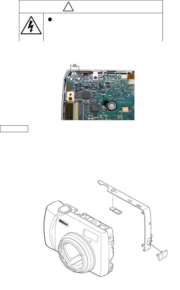
WARNING
Due to an internal high voltage area, take extra care not to get
an electric shock when detaching covers.
 After removing covers, be sure to discharge the main condenser according to the instructions of repair manuals.
Points to notice for Lead-free solder products
Lead-free solder is used for this product.
For soldering work, the special solder and soldering iron are required.
Do NOT mix up lead-free solder with traditional solder.
Use the special soldering iron respectively for lead-free solder and lead solder. They cannot be used in common.
Caution:
Be sure to remove the SD memory card and batteries before disassembly.
When disassembling, make sure to memorize the processing state of wires, screws to be fixed and their types, etc.
Because electrical parts are easily damaged by static electricity, make sure that you are well earthed/grounded.
- 1 -
VBA42003-R.3672.A
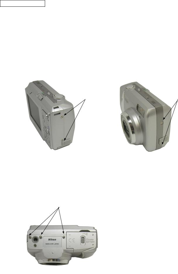
Removal of Rear cover
Removal of Exterior screws
Take out two screws (#804).
Take out two screws (#806).
#804 |
#806 |
Take out three screws (#804).
#804
- 2 -
VBA42003-R.3672.A
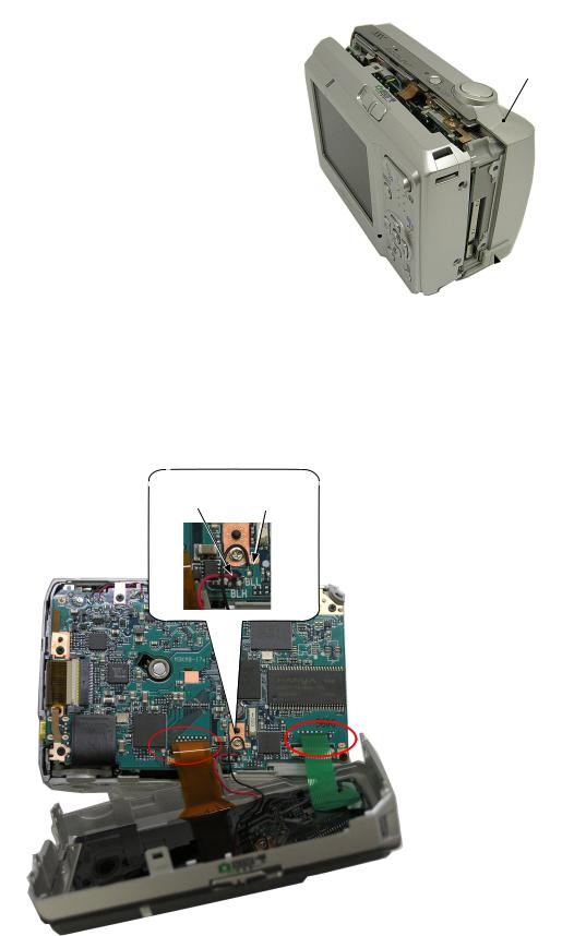
Removal of Rear cover
Open the battery lid.
Remove the rear cover (#B102) from the front
cover (#B101). |
#B101 |
Remove theAC adapter window (#391).
#B102 
 #391
#391
Remove two solders of TFT lead wires (red and black).
Remove two connectors from the rear cover.
Red Black
- 3 -
VBA42003-R.3672.A
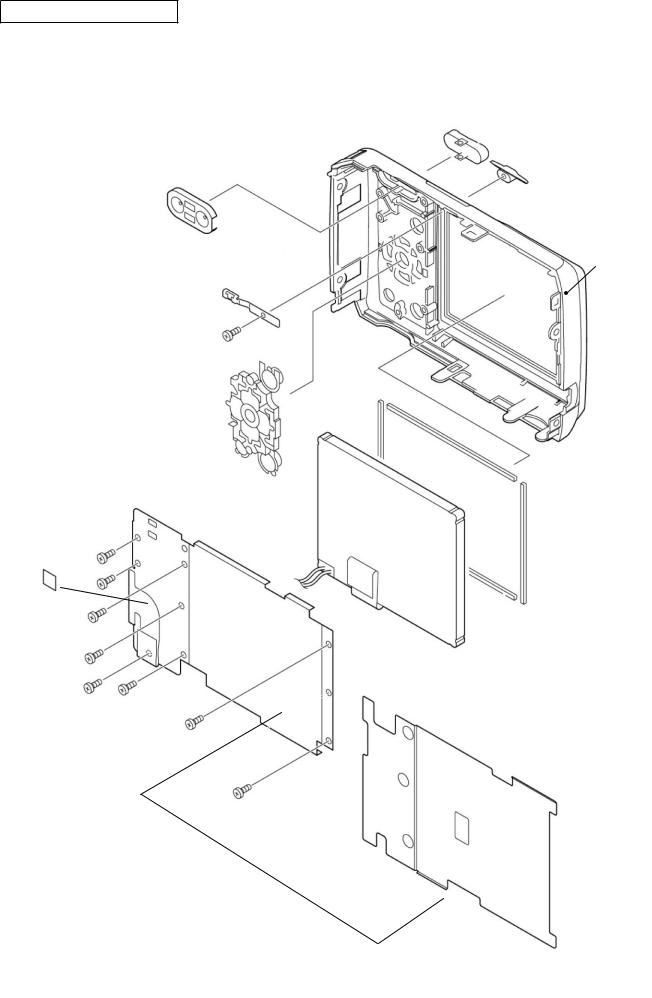
Disassembly of Rear cover
#221
#231
#222
#RP
#232
#802
#241
#1009
#165×2
#715
#166×2
#B1016
#801×8
#173
- 4 -
VBA42003-R.3672.A
WARNING
Due to an internal high voltage area, take extra care not to get
an electric shock when detaching covers.
 After removing covers, be sure to discharge the main condenser according to the instructions of repair manuals.
Discharge of Main condenser |
2KΩ/5W |
Front cover
Removal of Belt
Remove the belt (#104) from the front cover (#B101).
Remove the USB connector lid (#392).
#104
#215
#B101 #392
- 5 -
VBA42003-R.3672.A
Removal of Front cover and Lens-barrel curtain
Lift upwards at the shutter-releasing (red-circled) part, and detach the front cover (#B101). Note) Be careful not to hook the front cover to the release SW.
#B101
Lift upwards at the shutter-releasing part to detach the front cover.
(Caution)
When the front cover is removed,  it is easily hooked here.
Remove the lens-barrel curtain (#614).
#614
- 6 -

VBA42003-R.3672.A
Battery lid
Hold the back-door release SW towards the direction of the arrow. Remove the shaft (#357), which is firmly fixed, by pushing it out.
fig1.
#801×2
#354
#355
#352
#353
#351
#357
Fig1.
- 7 -

VBA42003-R.3672.A
Upper FPC
Take out two screws (#801).
Lift the upper FPC (#B1008) and remove the connector.
Remove the upper FPC.
#801×2
#B1008
Connector
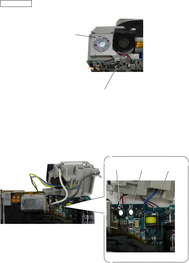
Unsoldering
Remove six solders of lead wires.
Speaker (Black) |
Microphone (Black) |
Self-timer LED (Blue) |
Speaker (Red) |
Microphone (Red) |
Self-timer LED (Yellow) |
- 8 -
VBA42003-R.3672.A
SB base plate
Take out the screw (#802). |
|
Remove the lug plate (#424). |
#424 |
#802
Remove two solders of the SB lead wires (white and gray).
Remove the solder of the trigger lead wire (Blue).
White Gray Blue
- 9 -
VBA42003-R.3672.A
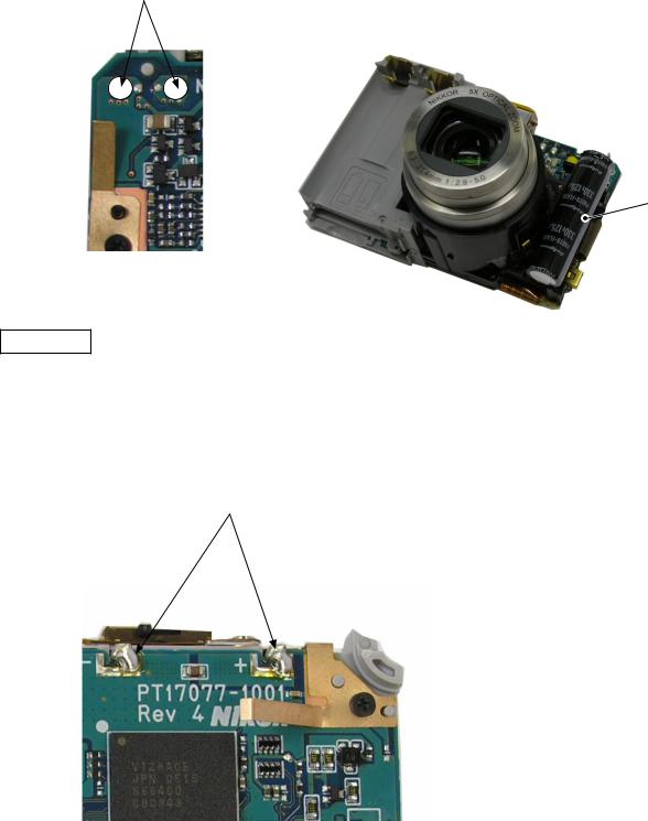
Removal of Condenser
Remove two solders to detach the condenser (#1018).
Unsolder ×2 to remove the condenser.
#1018
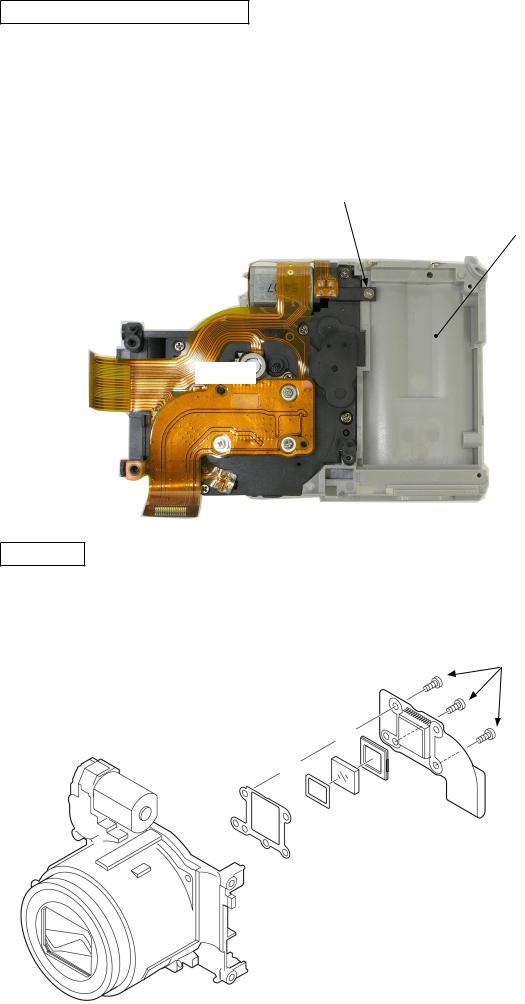
Main PCB
Removal of solder joints of Main PCB and Battery contacts
Unsolder ×2
- 10 -
VBA42003-R.3672.A
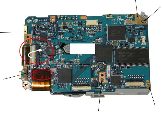
Removal of Finger, Connector, and Main PCB
Take out the screw (#802) to remove the finger (#172).
Take out the screw (#802) to remove the finger (#174).
Take out the screw (#802) to remove the finger (#175).
Take out the screw (#803).
Take out the screw (#802).
Remove two FPCs from the connectors.
Remove the main PCB (#1001).
#174
#802
#172
#802 
#1001
#175 #802 
#802
#803
- 11 -
VBA42003-R.3672.A
Lens-barrel large unit / Battery holder
Take out the screw (#802).
Remove the battery holder (#B358) from the lens-barrel large unit (#B10600).
#802
#B358
#B10600
CCD unit
Take out three screws (#807).
Remove the CCD unit (#B1003).
#807×3
#B1003
#672
#10
#643
#677
- 12 -

VAA42003-R.3672.A
Points to notice for disassembling/(re)assembling Lens-barrel unit
Caution) When the lens barrel is singly repaired and if the following parts are replaced, the lens unit checking tool is required for the FFD inspection and adjustment. Therefore, do NOT replace parts until the tool is prepared.
1st lens group
2nd lens group
CCD mount
Tools required for FFD inspection and adjustment
Caution) When the lens barrel unit of the product is repaired, the following tools are required for checking the operation and adjustment of the lens-barrel unit. Therefore, do NOT replace parts until the follawing tools are prepared.
Lens unit checking tool
Connecting cable for lens
PCI I/F board
Connection cable for PC
Adjusting focus stand for APS
Adapter for J XXXX
L1 lens-barrel driving software
- 13 -
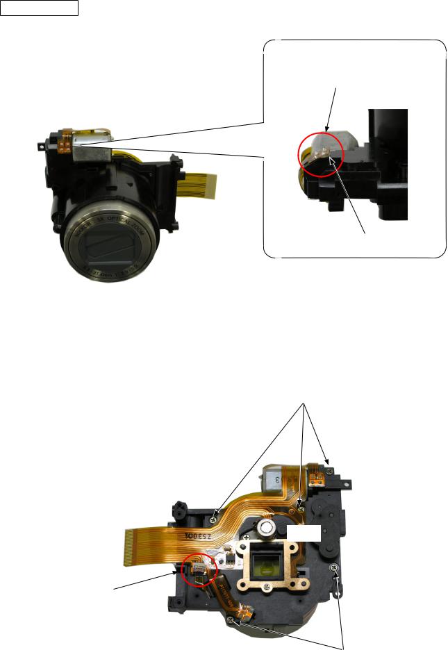
VAA42003-R.3672.A
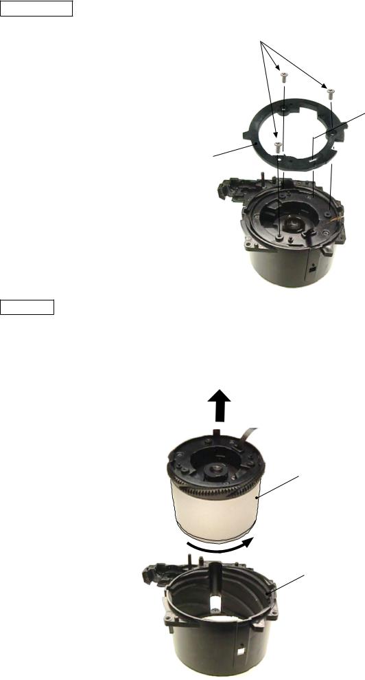
CCD Mount
Remove the
PI sensor
Adhesive
Disconnect the connector.
Take out five screws (#693).
Remove the CCD stand unit (#B601).
#693
#B601
Connector
#693
- 14 -
VAA42003-R.3672.A
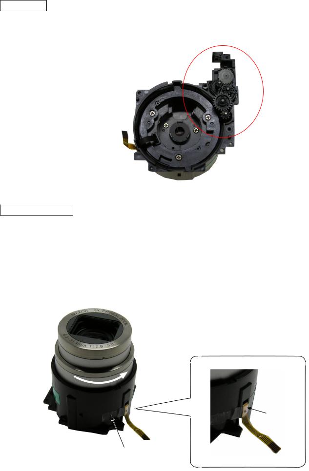
Zoom gear
Remove five gears.
Shutter FPC retainer
Turn the lens-barrel in the direction of the arrow, and extend the lens-barrel out.
Remove the polyester tape (#683).
Remove the shutter FPC retainer (#625).
Pull the FPC out by passing it through the hole.
Be careful not to damage the cam tube, when the FPC retainer (#625) is removed.
#625
#683
- 15 -
VAA42003-R.3672.A
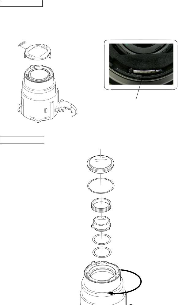
1st lens-group tube cover ring
Remove the 1st lens-group tube cover ring (#613) from the Barrier unit (#B631).
#613
Get alcohol to seep down from the clearance, and remove the cover ring slowly.
#B631
Barrier unit
Release two hooks to remove the barrier unit.
Self-made tool for removing the barrier unit ref.
Use a self-made tool of which the tip is converted.
Remove the barrier unit with enough care, because the hooks can be easily broken.
Hook×2
- 16 -
Barrier rotor plate
Remove the spring (#636).
Remove the rotor plate (#632).
#636
#632
1st and 2nd lens group
Turn the lens-barrel in the direction of the arrow to retract it.
Remove the 1st lens group(#B608).
Remove the 2nd lens group(#B609).
VAA42003-R.3672.A
#636
#B608
#B673
#618
#B609
#B676
#B675
- 17 -
VAA42003-R.3672.A
Straight ring
#692×3
Take out three screws (#692).Remove the straight ring (#611).
FPC hole
#611
Fixed tube
Turn the cam tube unit (#B603) in the direction of the arrow, and remove it from the fixed tube (#602).
#B603
#602
- 18 -
 Loading...