


INC
JAA79051-R.3624.A
AF-S DX Zoom-Nikkor
ED 18-70mm f/3.5-4.5G IF
JAA79051
REPAIR MANUAL
NIKON CORPORATION
Tokyo, Japan
Copyright 2004 by Nikon Corporation.
Recycled paper |
All Rights Reserved. |
|
Printed in Japan February 2004
INC
JAA79051-R.3624.A
SPECIFICATIONS
This lens can be used for Nikon digital SLR camera only.
Type of lens |
G-typeAF DX ZoomNikkor lens having built-in CPU and Nikon bayonet mount |
|
|
Focal length |
18mm-70mm |
|
|
Maximum aperture |
f/3.5-4.5 |
|
|
Lens construction |
15 elements in 13 groups (1 aspherical lens and 3 ED lens elements) |
|
|
Picture angle |
76°-22°50′with Nikon Digital Camera D1/D1H/D1X/D2H/D100) |
|
|
Focal length scale |
18,24,35,50,70mm |
|
|
Distance information |
Output to camera body |
|
|
Zoom control |
Manually via separate zoom ring |
|
|
Focusing |
Nikon Internal Focusing (IF) system (utilizing an internal Silent Wave Motor); |
|
manually via separate focus ring |
|
|
Shooting distance scale |
Graduated in meters and feet from 0.38m (2ft.) to infinity (∞) |
|
|
Closest focus distance |
0.38m (1.2ft.) at all zoom settings |
|
|
Diaphragm |
Fully automatic |
|
|
Aperture range |
f/3.5 to f/22 (at 18mm), f/4.5 to f/29 (at 70mm) |
|
|
Exposure measurement |
Via full-aperture method with cameras having CPU interface system |
|
|
Attachment size |
67mm (P 0.75mm) |
|
|
Dimensions |
Approx. 73mm dia. ×75.5mm extension from the camera's lens mount flange |
|
(min. length at 18mm focal length) |
|
|
Weight |
Approx.420g (14.8 oz) |
|
|
- M1 AF-S DX18-70/3.5-4.5G -
INC
JAA79051-R.3624.A
DISASSEMBLY/ASSEMBLY/ADJUSTMENT
1. DISASSEMBLY
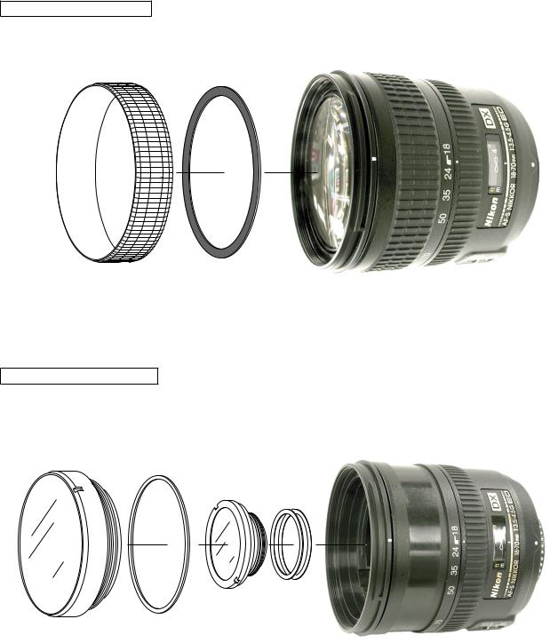
RUBBER RING, SHEET
35 |
48 |
|
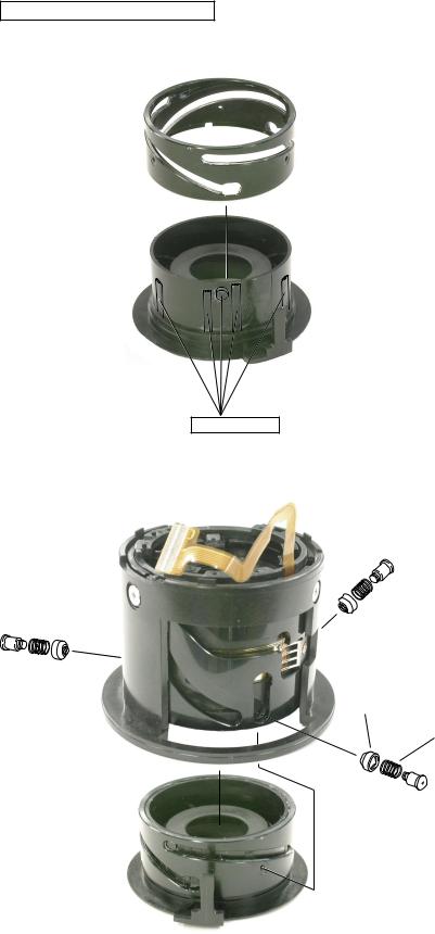
1stAND 2nd LENS GROUP
1st lens group unit |
77 |
|
79
2nd lens group unit
- L1 AF-S DX18-70/3.5-4.5G -

INC
JAA79051-R.3624.A
FILTER RING
 96 × 3
25
● Remove 3 screws (#96) and remove the filter
ring (#25) while rotating it in the arrow direction.
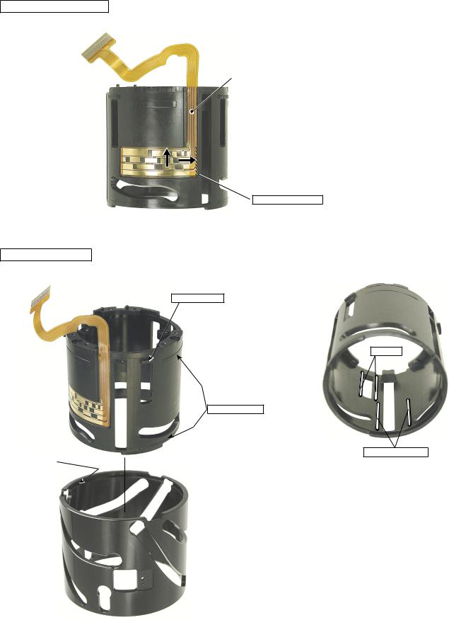
ZOOM RING
Remove the screw (#61).
61
- L2 AF-S DX18-70/3.5-4.5G -
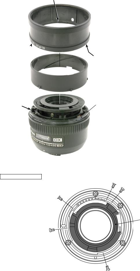
Convex section
Zoom ring
Convex section
Convex section
38
Groove |
|
22 |
|
REAR COVER RING
INC
JAA79051-R.3624.A
Remove the zoom ring.
Note
The three convex sections on the inner diameter of zoom ring are put into the groove of #22.
When removing the zoom ring, rotate it until the convex sections can be removed from the groove and then remove it.
105 × 2
Rear cover ring
107 × 3
- L3 AF-S DX18-70/3.5-4.5G -
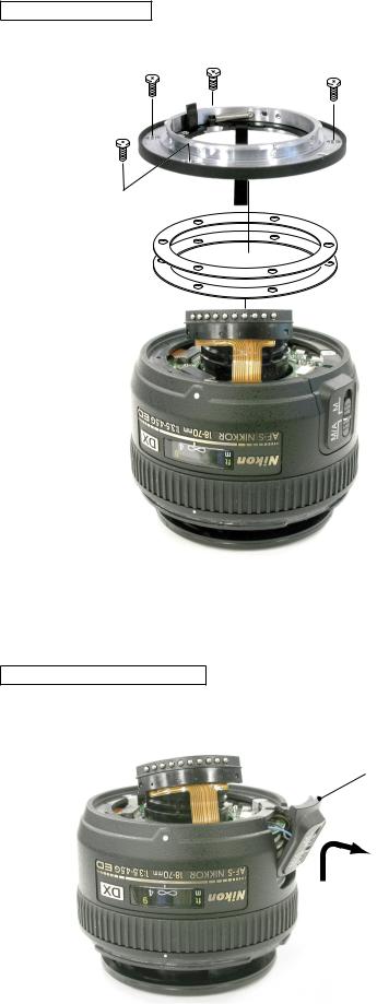
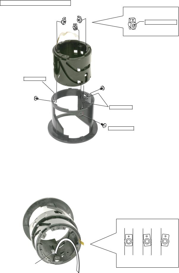
BAYONET MOUNT
116
INC
JAA79051-R.3624.A
98 × 3
Remove 3 screws (#98) and the screw (#116), and detach the bayonet mount.
Remove the washers (#78).
78
INDEX RING, FOCUS RING
M/Aselector switch
Slide the M/Aselector switch unit in the arrow direction as shown in the left picture.
- L4 AF-S DX18-70/3.5-4.5G -
INC
JAA79051-R.3624.A
Index ring
Focus ring
Remove the index ring first then the focus ring.
As shown in the left picture, pass the
M/Aselector switch unit through the
index ring.
M/Aselector switch
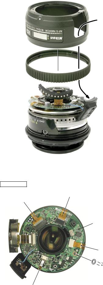
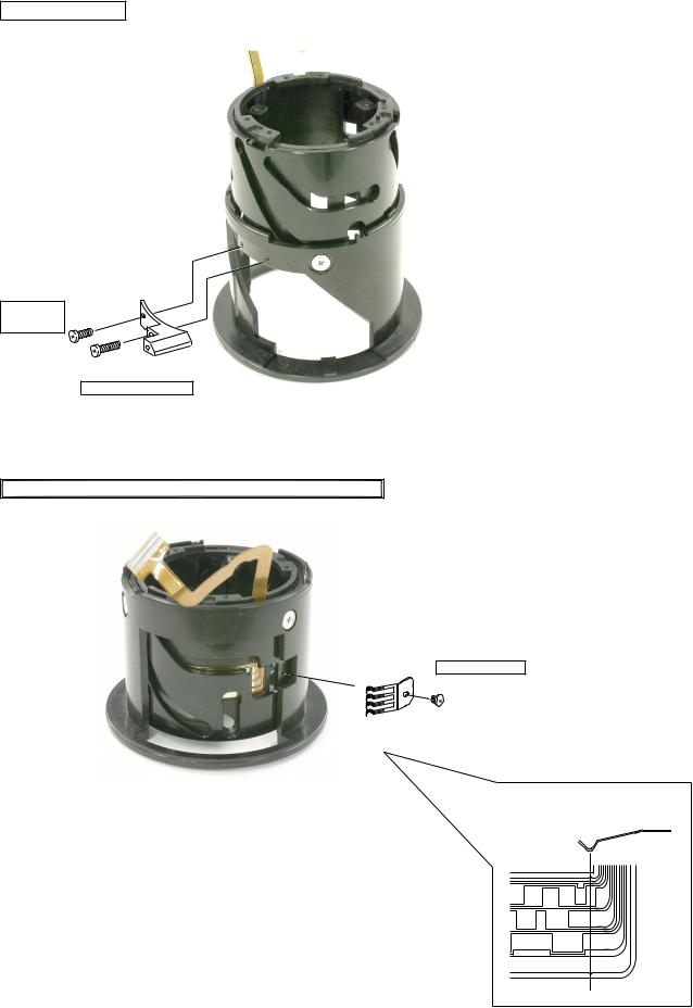
MAIN PCB
Distance encoder FPC |
|
Zoom encoder FPC |
Remove each FPC from the connectors as |
|
shown in the left . |
Main PCB |
Remove the screw (#115). |
|
Remove the main PCB. |
97  115
115
MR sensor FPC
- L5 AF-S DX18-70/3.5-4.5G -
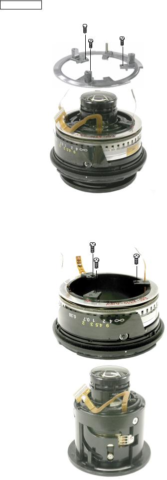
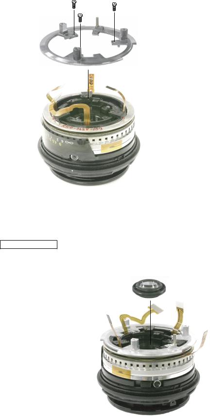
SWM UNIT

 96 × 3
29
INC
JAA79051-R.3624.A
Remove 3 screws (#96), and detach the Rear fixed ring (#29).
96 × 3
Remove 3 screws (#96), and detach the SWM unit.
SWM unit
- L6 AF-S DX18-70/3.5-4.5G -
INC
JAA79051-R.3624.A
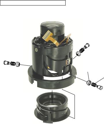
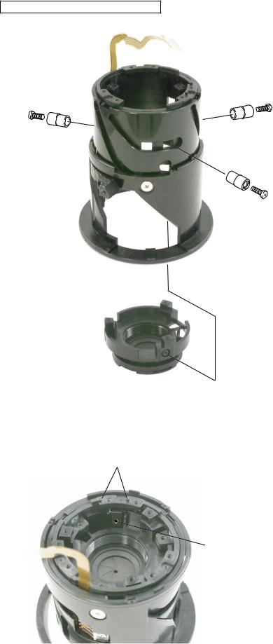
2nd LENS GROUP HOUSING UNIT
Remove 3 screws (#84), 3 springs (#86) and 3 rollers #(85).
85 × 3
86 × 3
84 × 3
2nd lens group housing unit
Note
After the above, the 5th and 4th lens groups should be removed.
When the 5th and 4th lens groups are removed, lens alignment should be performed after assembly.
If the alignment is impossible in the service office, do not carry out further disassembly work, but the zoom encoder brush and zoom key can be replaced.
- L7 AF-S DX18-70/3.5-4.5G -
INC
JAA79051-R.3624.A
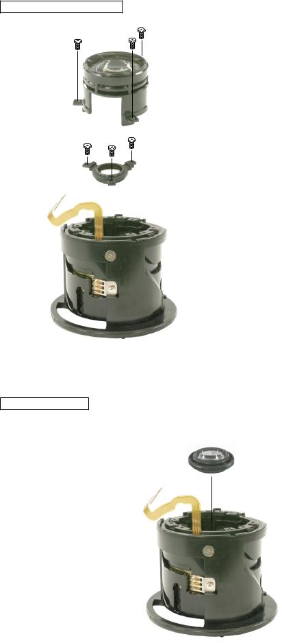
4thAND 5th LENS GROUP
96 × 3 |
Remove 3 screws (#96) and detach the 5th lens |
|
|
|
group. |
|
Remove 3 screws (#96) and detach the 4th lens |
5th lens group |
group. |
96 × 3
4th lens group
3rd LENS GROUP
3rd lens group
- L8 AF-S DX18-70/3.5-4.5G -
INC
JAA79051-R.3624.A
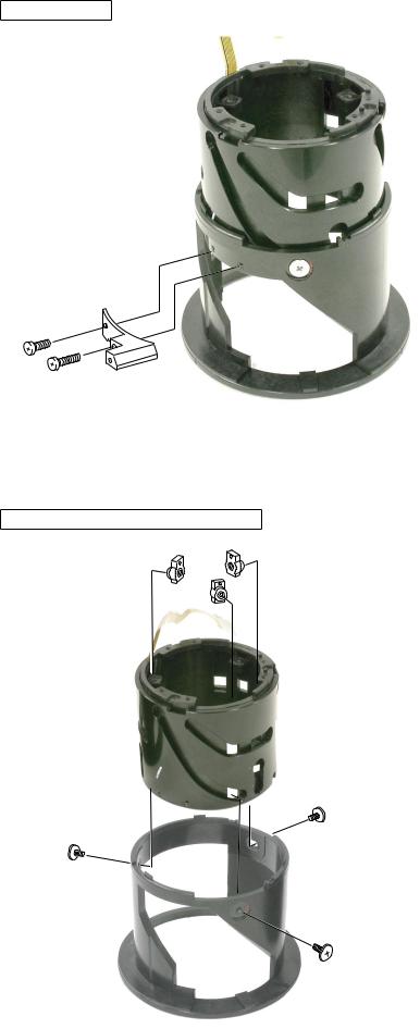
APERTURE BLADE HOUSING UNIT
Remove 3 screws (#80), 3 rollers (#83), and detach the Aperture blade housing unit.
83 × 3
80 × 3
Aperture blade housing unit
ZOOM ENCODER BRUSH
Remove 3 screws (#75) and detach the zoom encoder brush (#74).
75
74
- L9 AF-S DX18-70/3.5-4.5G -
ZOOM KEY
60
62 |
59 |
|
1st LENS GROUP SLIDING RING
B7 × 3
81 × 3
51
INC
JAA79051-R.3624.A
Remove the screws (#60 and #62) and detach the zoom key (#59).
Remove 3 screws (#51), the three zoom keys (B7) and detach the 1st lens group sliding ring (#51).
Remove the 1st sliding ring (#51).
- L10 AF-S DX18-70/3.5-4.5G -

INC
JAA79051-R.3624.A
CAM RING
50
- L11 AF-S DX18-70/3.5-4.5G -
INC
JAA79051-R.3624.A
2.ASSEMBLY/ADJUSTMENT
ZOOM ENCODER FPC
1002 By aligning the edges as shown by the left arrows, adhere the zoom encoder FPC (#1002) to #24.
24
Adhesive:Aron alpha
CAM RING GROUP
3 convex places on outer diameter
Grease:I-40
|
24 |
|
MZ-800S |
24 |
|
|
3 sliding places on outer diameter |
|
Grease:I-40 |
Horizontal groove |
Grease: MZ-800S |
|
|
● Grease application: |
50 |
Apply MZ-800S to 6 straight grooves of #24. |
Apply I-40 to 3 cam grooves of #24.
Apply I-40 to 9 cam grooves and horizontal groove of #50.
- L12 AF-S DX18-70/3.5-4.5G -
INC
JAA79051-R.3624.A
1st LENS GROUP SLIDING RING
B7 × 3 |
B7 |
Adhesive: Lock END B
Grease: I-40
Grease: I-40
81 × 3
Adhesive:ScrewLock
51
Reference
Tighting the screws (#81) causes inclination of B7, and it becomes heavy in operating the cam ring. Therefore, as shown below, put a back washer, etc. in
between B7 and the straight groove and tighten the screws (#81). This can prevent B7 from being inclined.
B7
○ × ×
B7
Back washer (Thickness: 0.4mm)
- L13 AF-S DX18-70/3.5-4.5G -
INC
JAA79051-R.3624.A
ZOOM KEY
Attach the zoom key #59 with the screws (#60 and #62).
Adhesive:
Lock End B
60
62 |
59 |
|
Adhesive: Lock End B
ADJUSTMENT OF ZOOM ENCODER BRUSH POSITION
Adhesive:ScrewLock
75
74
74
Set the zoom encoder brush #74. Tighten the screw #75temporarily.
Set the cam ring to the W side as shown in the above picture.
Adjust the brush position so that the edge of the brush are positioned as shown right.
Tighten the screw (#75) securely and fix it with the screw lock.
- L14 AF-S DX18-70/3.5-4.5G -
INC
JAA79051-R.3624.A
APERTURE BLADE HOUSING UNIT
83 × 3
80 × 3
Aperture blade housing unit
Convex section
Aperture lever
Assemble the zoom Aperture blade housing unit with 3 screws (#80) and 3 rollers (#83).
Check When mounting the aperture blade chamber unit, the aperture lever must be positioned as shown left.
- L15 AF-S DX18-70/3.5-4.5G -
INC
JAA79051-R.3624.A
2nd LENS GROUP HOUSING UNIT
52
● Apply G92KAto the 3 cam grooves of #52.
56
Grease: G92KA
Apply to 2 convexties on outer diameter
Assemble the 2nd lens group with 3 rollers (#85), 3 springs #86 and 3 screws (#84).
85 × 3
86 × 3
84 × 3
2nd lens group housing unit
- L16 AF-S DX18-70/3.5-4.5G -
INC
JAA79051-R.3624.A
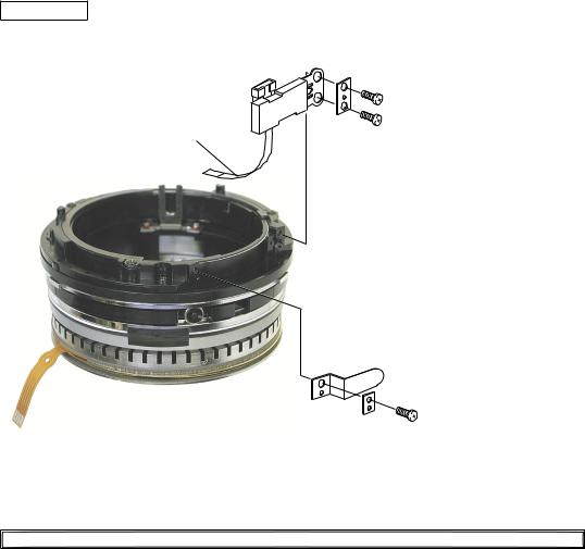
MR HEAD
MR head
MR sensor FPC
534
541 × 2
Set the MR head to be parallel with themagnetic tape.
 Magnetic tape
533 |
|
SWM unit |
|
536 |
543 |
|
Adhere the MR sensor FPC to the insideof the SWM unit.
Note Adhere the MR sensor FPC not to be largely slack.
INSPECTIONANDADJUSTMENT FOR THE WAVEFORM OUTPUT FROM MR ENCODER
● In case of disassembling or replacing the MR head, be sure to conduct adjustment.
Equipment and tools required
Single output rated voltage power supply: 1 unit With 5.0V and 100mA, applicable to the self-made toolOscilloscope: 1 unit
Self-made tool: 1 unit
Note In case of any trouble in continuity between the self-made tool and the contacts of relay FPC, there may be dust, corrosion or oxidation on the contact surface of relay FPC. Be sure to polish the contact surface prior to getting connected with the self-made tool.
Preparation for measuring lens
Assemble the SWM unit, on which the MR head is already attached, and the MF ring into the cam ring unit.
Then, connect to the measuring devices. (Refer to the next page.)
- L17 AF-S DX18-70/3.5-4.5G -
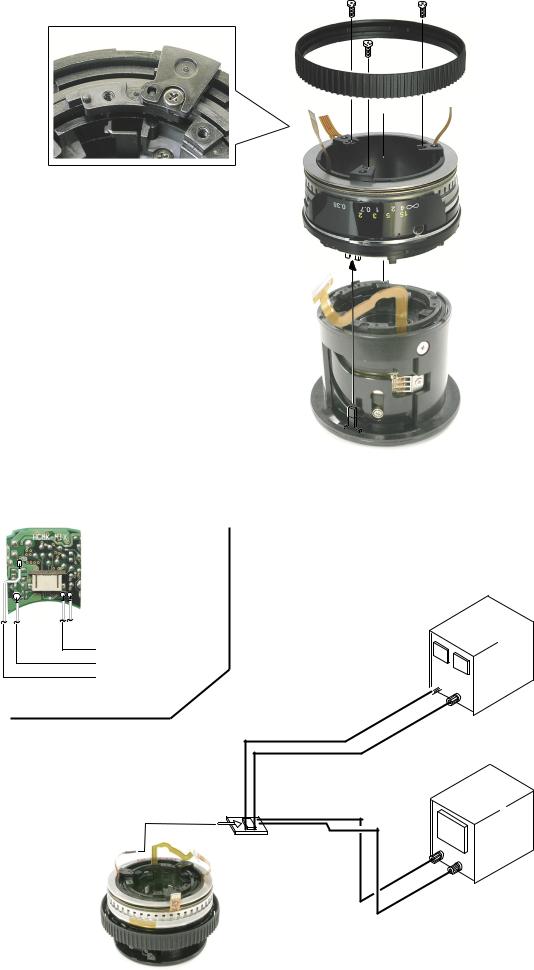
Connection diagram
 Oscilloscope(2ch)
Oscilloscope(1ch)
Power supply(+)
Power supply(-)
INC
JAA79051-R.3624.A
96 × 3
Focus ring
SWM unit
Cam ring unit
 Set values
5.0V
100mA
GND 
Power supply
Self-made tool |
Oscilloscope2ch
- L18 AF-S DX18-70/3.5-4.5G -
INC
JAA79051-R.3624.A
How to conduct inspection and adjustment
Make sure that the current and voltage of the connected rated voltage power supply are set values.Then, turn on the power.
Set the oscilloscope and turn the focus ring by hand.
Note Because the shape of waveform varies according to the driving speed of focus ring, set Time/Div accordingly.
In case of detecting any wide waveform noise, use the filter function.
How to set the filer function by Yokogawa-manufactured DL1540
Press the filter button.
Select "Smooth" in the menu on the PC screen.
CH1=20mV |
CH2=20mV |
5ms/div |
AC 10:1 |
AC 10:1 |
|
|
|
NORM 200KS/s |
CH1
CH2
●Setting of oscilloscope |
|
|
V/Div CH1 |
|
|
V/Div CH2 |
|
|
Coupling |
|
|
Time/Div |
|
m Sec |
Trigger Mode |
NORMAL |
|
Trigger Coupling |
|
|
Trigger Source |
|
|
Trigger Position |
div |
|
Trigger Type |
EDGE |
|
Trigger Level |
|
|
Standard The amplitude of every pulse/waveform should be 50mV or more.
Note Check the waveform by letting the focus ring to travel from the infinity-end to the near distance end and vice versa.
- L19 AF-S DX18-70/3.5-4.5G -
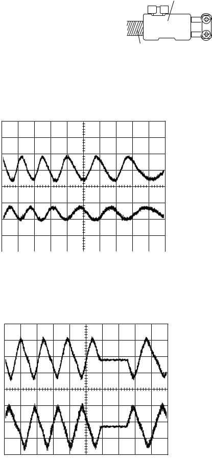
In the case of small amplitude, make an adjustment by loosen 2 screws #541 to shift the MR head position as shown right.
Note
During adjustment, prevent the magnetic tape and MR head from touching the magnetized driver bit, or the magnetic data may be damaged.
INC
JAA79051-R.3624.A
MR head


 541 × 2
Magnetic tape
Reference
● In case the amplitude of either CH1 or CH2 is smaller, one of 2 screws #541 may be loosened, so check for it. But if this is not the case, the MR head is regarded as malfunctioning. Be sure to replace the MR head unit (B15) and adjust it again.
CH1=20mV |
CH2=20mV |
5ms/div |
AC 10:1 |
AC 10:1 |
|
|
|
NORM 200KS/s |
CH1
CH2
● In case there is a partial drop in the amplitude between the infinity and the near distance, the magnetic data of magnetic tape may be damaged. Then, replace the magnetic tape and adjust it again.
CH1=20mV |
CH2=20mV |
5ms/div |
AC 10:1 |
AC 10:1 |
|
|
|
NORM 200KS/s |
CH1
CH2
Turn off the rated voltage power supply and remove the SWM unit.
- L20 AF-S DX18-70/3.5-4.5G -

INC
JAA79051-R.3624.A
ZOOM RING FIXING RING
Note When mounting #22, do NOT allow it to touch the MR head. If external pressure is applied to the MR head, it causes misalignment and changes the accuracy.
96 × 4
22
67
● Adhere #67 to the zoom ring fixing ring (#22) and apply the oil barrier to the whole #67.
|
Assemble the SWM unit |
|
INSTALLATION OF THE SWM UNIT |
||
with 3 screws (#93). |
||
|
||
|
96 × 3 |
- L21 AF-S DX18-70/3.5-4.5G -
INC
JAA79051-R.3624.A
96 × 3
Set the rear fixed ring (#29) with 3 screws (#96).
29
3rd LENS GROUP
3rd lens group
- L22 AF-S DX18-70/3.5-4.5G -
 Loading...