


NEC PX-42M2G, PX-42M2A Service Manual
MODEL PX-42M2A
PX-42M2G
PlasmaSync™ Multimedia Monitor
SERVICE MANUAL
PART No. 399910943
Better Service
Better Reputation
Better Profit
SAFETY CAUTION:
Before servicing this chassis, it is important that the service technician read and follow the “Safety Precautions” and “Product Safety Notice” in this Service Manual.
WARNING:
SHOCK HAZARD - Use an isolation transformer when servicing.

CONTENTS
SAFETY PRECAUTIONS .................................................................................................................................. |
2-1 |
USERS MANUAL ............................................................................................................................................... |
3-1 |
TROUBLE SHOOTING ...................................................................................................................................... |
4-1 |
METHOD OF ADJUSTMENTS .......................................................................................................................... |
5-1 |
CIRCUIT DESCRIPTION ................................................................................................................................... |
6-1 |
METHOD OF DISASSEMBLY ........................................................................................................................... |
7-1 |
DISASSEMBLY .................................................................................................................................................. |
8-1 |
METHOD OF WIRING ....................................................................................................................................... |
9-1 |
PACKAGING .................................................................................................................................................... |
10-1 |
REPLACEMENT PART LIST ........................................................................................................................... |
11-1 |
CONNECTION DIAGRAMS ............................................................................................................................. |
12-1 |
BLOCK DIAGRAM ........................................................................................................................................... |
13-1 |
SCHEMATIC DIAGRAMS ................................................................................................................................ |
14-1 |
VI/O PWB (PWC-4213B) ............................................................................................................................ |
14-1 |
ANALOG PWB (PWC-4214) ....................................................................................................................... |
14-3 |
VIDEO PWB (PWC-4213A) ...................................................................................................................... |
14-15 |
AUDIO PWB (PWC-4216A) ...................................................................................................................... |
14-20 |
SOUND PWB (PWC-4216B) .................................................................................................................... |
14-23 |
POWER PWB (PWC-4216G) ................................................................................................................... |
14-25 |
CTL PWB (PWC-4216F) ........................................................................................................................... |
14-26 |
VOL PWB (PWC-4216C) .......................................................................................................................... |
14-27 |
R TERMINAL PWB (PWC-4216E) ............................................................................................................ |
14-28 |
L TERMINAL PWB (PWC-4216D) ............................................................................................................ |
14-29 |
CAUTION
In transporting the product, be sure to use the specified box. If the product does not have the specified stand, attach the stand, then pack the project. Packing the product without the specified stand and transporting it could cause a product failure.
1-1

SAFETY PRECAUTIONS
CAUTION |
RISK OF ELECTRIC SHOCK |
DO NOT OPEN |
CAUTION: TO REDUCE THE RISK OF ELECTRIC SHOCK, DO NOT OPEN TOP COVER. NO USER-SERVICEABLE PARTS INSIDE. REFER SERVICING TO QUALIFIED SERVICE PERSONNEL.
This symbol warns the user that uninsulated voltage within the unit may have sufficient magnitude to cause electric shock. Therefore, it is dangerous to make any kind of contact with any part inside of this unit.
This symbol alerts the user that important literature concerning the operation and maintenance of this unit has been included.
Therefore, it should be read carefully in order to avoid any problems.
ATTENTION |
RISQUE D'ELECTROCUTION |
NE PAS OUVRIR |
ATTENTION: POUR EVITER LES RISQUES D' ELECTROCUTION, NE PAS ENLEVER LE CONVERCLE SUPERIEUR. AUCUN
DES ELEMENTS INTERNES NE DOIT ETRE REPARE PAR L'UTILISATEUR. NE CONFIER L' ENTRETIEN QU'A UN
PERSONNEL QUALIFIE.
L'éclair fléché dans un triangle équilatéral est destiné à avertir l'utilisateur de la présence, dans l'appareil, d'une zone non-isolée soumise à une haute tension dont l'intensité est suffisante pour constituer un risque d'électrocution.
Le point d'exclamation dans un triangle équilatéral est destiné à attirer l' attention de l'utilisateur sur la présence d'informations de founctionnement et d'entretien importantes dans la brochure accompagnant l'appareil.
WARNING
HEATSINK MAY BE ENERGIZED. TEST BEFORE TOUCHING.
2-1
SAFETY PRECAUTIONS
1.Before returning an instrument to the customer, always make a safety check of the entire instrument, including, but not limited to, the following items.
a.Be sure that no built-in protective devices are defective and/or have been defeated during servicing. (1) Protective shields are provided on this chassis to protect both the technician and the customer. Correctly replace all missing protective shields, including any removed for servicing convenience. (2) When reinstalling the chassis and/or other assembly in the cabinet, be sure to put back in place all protective devices, including,but not limited to, nonmetallic control knobs,insulating fishpapers,adjustment and compartment covers/shields, and isolation resistor/capacitor networks. Do not operate this instrument or permit it to be operated without all protective devices correctly installed and functioning.
b.Be sure that there are no cabinet openings through which an adult or child might be able to insert their fingers and contact a hazardous voltage. Such opening include,but are not limited to,
(1) spacing between the picture tube and the cabinet mask, (2) excessively wide cabinet ventilation slots, and (3) an improperly fitted and/or incorrectly secured cabinet back cover.
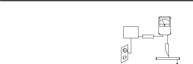
c.Leakage Current Hot Check — With the instrument completely reassembled,plug the AC line cord directly into a 120V AC outlet (PX-42M2G : 240V AC outlet). (Do not use an isolation transformer during this test.) Use a leakage current tester or a metering system that complies with American National Standards Institutes (ANSI) C101.1 Leakage Current for Appliances and Underwriters Laboratories(UL) 1950. With the instrument AC switch first in the ON position and then in the OFF position, measure from a known earth ground (metal waterpipe, conduit,etc.) to all exposed metal parts of the instrument(antennas, handle bracket, metal cabinet, screwheads, metallic overlays, control shafts,etc.), especially any exposed metal parts that offer an electrical return path to the chassis. Any current measured must not exceed 3.5 milliamp. Reverse the instrument power cord plug in the outlet and repeat test.ANY MEA-
SUREMENTS NOT WITHIN THE LIMITS SPECIFIED HEREIN INDICATE A POTENTIAL SHOCK HAZARD THAT MUST BE ELIMINATED BEFORE RETURNING THE INSTRUMENT TO THE CUSTOMER.
AC Leakage Test
|
(READING SHOULD |
|
|
NOT BE ABOVE |
|
|
3.5 mA) |
|
DEVICE |
LEAKAGE |
|
CURRENT |
||
UNDER |
||
TESTER |
||
TEST |
||
|
||
|
+ – |
|
TEST ALL |
|
|
EXPOSED METAL |
|
|
SURFACES |
|
|
3-WIRE CORD |
|
|
ALSO TEST WITH |
|
|
PLUG REVERSED |
|
|
(USING AC ADAPTER |
EARTH |
|
PLUG AS REQUIRED) |
||
GROUND |
||
|
2.Read and comply with all caution and safety-related notes on or inside the Monitor cabinet, on the Projection Monitor chassis, or on the picture tube.
3.Design Alteration Warning — Do not alter or add to the mechanical or electrical design of this unit. Design alterations and additions, including, but not limited to, circuit modifications and the addition of the items such as auxiliary audio and/or video output connections might alter the safety characteristics of this Monitor and create a hazard to the user. Any design alterations or additions will void the manufacturer's warranty and will make you,the servicer,responsible for personal injury or property damage resulting therefrom.
4.Hot Chassis Warning — a. Some MultiSync Monitor chassis are electrically connected directly to one conductor of the AC power cord and may be safely serviced without an isolation transformer only if the AC power plug is inserted so that the chassis is connected to the ground side of the AC power source. To confirm that the AC power plug is inserted correctly, with an AC voltmeter measure between the chassis and a known earth ground. If a voltage reading in excess of 1.0V is obtained, remove and reinsert the AC power plug in the opposite polarity and again measure the voltage potential between the chassis and a known earth ground. b. Some Projection Monitor chassis normally have 85V AC (RMS), between chassis and earth ground regardless of the AC plug polarity. These chassis can be safely serviced only with an isolation transformer inserted in the power line between the receiver and the AC power source, for both personnel and test equipment protection. c. Some Projection Monitor chassis have a secondary ground systems in addition to the main chassis ground. This secondary ground system is not isolated from the AC power line. The two ground system are electrically separated by insulating material that must not be defeated or altered.
2-2

SAFETY PRECAUTIONS
5.Observe original lead dress. Take extra care to assure correct lead dress in the following areas: a. near sharp edges, b. near thermally hot parts— be sure that leads and components do not touch thermally hot parts, c. the AC supply, d. high voltage, and e. antenna wiring. Always inspect in all areas for pinched, out-of-place, or frayed wiring. Do not change spacing between components, and between components and the printed-circuit board. Check AC power cord for damage.
6.Components,parts, and/or wiring that appear to have overheated or are otherwise damaged should be replaced with components, parts, or wiring that meet original specifications. Additionally,determine the cause of overheating and/or damage and, if necessary, take corrective action to remove any potential safety hazard.
7.PRODUCT SAFETY NOTICE —Many MultiSync Monitor electrical and mechanical parts have special safety-related characteristics some of which are often not evident from visual inspection, nor can the protection they give necessarily be obtained by replacing them with components rated for higher voltage, wattage, etc. Parts that have special safety characteristics are identified in this
service data by shading with a mark on schematics and by shading or a
 mark in the parts list. Use of a substitute replacement part that does not have the same safety characteristics as the recommended replacement part in this service data parts list might create shock, fire, and/or other hazards.
2-3

PRECAUTIONS DE SECURITE
1.Avant de remettre un appareil à un client, faire toujours d'abord un examen de sécurité de l'appareil en entier comprenant, mais ne s'y limitant pas les points cités ci-dessous:
a.Vérifier qu' aucun des dispositifs de protection ne soit défectueux ou n' ait été endommagé pendant les travaux.
(1)Les volets protecteurs sur ce châssis ont été montés pour protéger aussi bien le technicien que le client. Remplacer correctement tous les volets protecteurs manquants, aussi bien que ceux qui ont pu être enlevés pour la commodité des travaux.
(2)Quand vous remettez le châssis ou d'autres assemblages ensemble dans le coffret, vérifier qu' ont été remis à leur place tous les dispositifs de protection, comprenant mais ne s' y limitant point, les boutons de contrôle non-métalliques, les feuilles d'isolation, les couverture/volets de l'ajustement et du compartiment, et l'isolation des réseaux résistance/condensateur. Ne pas travailler sur cet appareil ni permettre qu'y soit effectué un travail sans que tous les dispositifs de protection n' y soient correctement installés fonctionnants.
b.Bien vérifier qu'il n'y ait aucune ouverture sur le coffret qui ne puisse permettre à un adulte ou à un enfant d'y faire pénétrer ses doigts et attraper une décharge électrique.
De telles ouvertures comprendraient sans pour autant s'y limiter (1) l'espace entre le tube à images et le coffret de l'eppareil, (2) les espaces excessivement ouverts pour la ventilation et (3) la couverture arrière du coffret improprement fixée ou incorrectement protegée.
c.Vérification de courant de fuite
L'appareil ayant été complètement réassemblé, brancher-le à une prise de courant de 120V (PX-42M2G : 240V). (Ne pas se servir d'un transformateur d'isolation pendant ce test). Se servir d'un vérificateur de courant d'excitation ou d'un système de mesure conforme aux normes ANSI (American National Standards Institute) C101.1 Leakage Current for Appliances et U. L (Underwriters Laboratories) 1950. Le bouton de l'appareil en position "Marche" et ensuite en position "Arrêt", mesurer à partir d'une prise de terre (métallique tuyauterie, conduite, etc...) à toutes les pièces métalliques de l'appareil exposées (antennes, poignet métalliques, coffren métallique, tête des vis, surfaces métalliques, traits de contrôle, etc.) surtout à toutes les pièces métalliques exposées qui peuvent reconduire le courant au châssis. En aucun cas, la mesure du
courant ne doit dépasser 3.5 milliamp. Inverser la fiche de courant de l'appareil dans la prise et répéter le test. Tout mesurage ne s'arrêtant pas aux limites spécifiées icicomporte un risque de décharge électrique dangereux, qui doit être éliminé, avant que l'appareil ne soit remis au client.
EXAMEN DE COURANT
D'EXCITATION
|
(LA MESURE DU COURANT |
|
|
NE DOIT PAS DEPASSER |
|
|
3.5 MILLIAMP) |
|
DISPOSIT IF |
|
|
SOUS |
VERIFICATEUR |
|
L ' EXAMEN |
||
DE CORANT |
||
+ – |
||
DE FUITE |
||
EXAMINER TOUTES |
|
|
LES PIECES METALLIQUES |
|
|
DEL' APPAREIL EXPOSEE |
|
|
3-CORDES DE FIL |
|
|
EXAMINER AVEC |
|
|
LA FICHE DE COURANT |
|
|
INVERSEE |
PRISE DE TERRE |
|
(SE SERVIR DE LA FICHE DE COURANT |
||
|
||
DE L' A DAPTATEUR COMME DEMANDEE) |
|
2.Lire et respecter toutes les mises en garde et notes de sécurité à l'intérieur ou à l'extérieur du coffret du rétro-projecteur, sur le châssis du rétro-projecteur ou sur le tube à images.
3.Mise en garde contre la modification du dessin
Ne pas modifier ni ajouter à la pièce mécanique ou électrique du modèle. Des modifications ou additions, comportant, mais ne s'y limitant pas, des modifications des circuits et l'addition d'éléments tels que des auxilliairs audio et/ou des branchements pour la prise de vidéo, pourrait éprouver la sécurité de ce rétro-projecteur et créer un risque pour l'utilisateur. Tout changement ou addition accomplie annulera la garantie du fabricant et va rendre votre service d'entretien, responsable des dommages corporels ou de biens en résultant.
4.Mise en garde contre le châssis sous tension
a.Certains châssis de rétro-projecteur sont électriquement reliés à un conducteur du fil de courant et ainsi peuvent ne comporter aucun risque sans un transformateur d'isolation seulement si la prise de courant est branchée, de manière que le châssis est relié à la prise de terre de la source de courant. Pour s'assurer que la prise de courant est correctement insérée, relever les mesures avec un voltmètre de courant entre le châssis et un point de prise de terre bien connu. Si le voltage indiqué est supérieur à 1,0V, débrancher et reinsérer la prise de courant dans la polarité contraire et une fois de plus remesurer le voltage potentiel entre le câssis et la prise de terre.
2-4

PRECAUTIONS DE SECURITE
b.Certains châssis de moniteur ont habituellement 85V (RMS) entre le châssis et la prise de terre, en fonction de la polarité de la prise de courant. Ces châssis peuvent ne comporter aucun risque seulement avec un transformateur d'isolation inséré dans la ligne de puissance située entre de rétro-projecteur et la source d'électricité, cela pour la protection aussi bien du personnel que du matériel de vérfication.
c.Certains châssis de rétro-projecteur ont un système secondaire de masse en addition avec le système principal de masse du châssis. Ce système secondaire de masse n'est pas isolé du courant électrique. Les deux systèmes sont électriquement séparés par du matériel d'isolation qu' on vérifiera bien qu'il ne soit ni altéré ni défectueux.
5.Vérifier la couverture originale en plomb. Accorder la plus grande attention à la couverture de plomb notamment aux endroits ci-dessous indiqués.
a.Près des bords aigus
b.près des parties très chaudes
Vérifier que les composants et les plombs ne touchent pas les parties très chaudes telles que:
c.l'alimentation du courant
d.la haute tension
e.Ies fils de l'antenne
Pousser l'inspection, à tous les endroits, à la recherche des cordes pincées, déplacées ou effilochées. Ne pas changer l'écartement entre composants, et entre composants et le tableau de circuit imprimé. Vérifier que le fil de conduite électrique est en bon état.
6.Les composants, parts (pièces) et/ou fils qui ont été trouvés surchauffés devraient être remplacés avec les composants, pièces et fils s'y reliant avec d'autre qui ont les mêmes spécifications que les originales. De plus, rechercher la cause du surchauffement et/ ou des dommages et si nécessaire, prendre les mesures propres pour prévenir tout risque potentiel.
7.Note sur sûreté de l'appareil
Beaucoup de pièce de rétro-projecteur, qu'elles soient électriques ou mécaniques, ont des dispositions de sécurité qui ne sont pas toujours évidentes d'une simple inspection visuelle et la protection qu'elles donnent nécessairement ne pourront être pas obtenues par les remplaçants avec des composants aux voltages ou watts plus élevés.
Les pièces qui ont des caractéristiques particulières de sécurité sont identifiées avec un trait  marqué sur les schémas et sont ombragés ou comportent un trait
  sur la liste des pièces. L'utilisation d'un produit substitutif qui n'aurait pas les mêmes caractéristiques comme il est recommandé dans ces données d'entretien pourrait provoquer une décharge électrique, un feu, et/ou d'autres dangers.
2-5

USERS MANUAL
3-1

USERS MANUAL
3-2
USERS MANUAL
3-3
USERS MANUAL
3-4

USERS MANUAL
3-5
USERS MANUAL
3-6
USERS MANUAL
3-7

USERS MANUAL
3-8

USERS MANUAL
3-9
USERS MANUAL
3-10
USERS MANUAL
3-11

USERS MANUAL
3-12

USERS MANUAL
3-13
USERS MANUAL
3-14

USERS MANUAL
3-15

USERS MANUAL
3-16

USERS MANUAL
3-17
USERS MANUAL
3-18
USERS MANUAL
3-19

USERS MANUAL
3-20

USERS MANUAL
3-21
USERS MANUAL
3-22

USERS MANUAL
3-23
 Loading...