


NEC Ruggedised Notebook Computer
User’s Manual
FC-N21S
Shortcut to Table of Contents

Information in this document is subject to change without notice.
No part of this manual may be reproduced in any form without the prior written permission of NEC Australia.
Microsoft and Windows are registered trademarks or trademarks of Microsoft Corporation in the United States and
other countries.
Intel, Intel Core, and Intel SpeedStep are registered trademarks or trademarks of Intel Corporation or their affiliate
companies in the United States and other countries.
SD is a trademark of SD Card Association.
ShieldPRO is a trademark of NEC Corporation in Japan.
DeviceProtector is a trademark of NEC Personal Products, Ltd.
Adobe, Adobe logo, and Acrobat are trademarks of Adobe Systems Incorporated in the United States and other
countries.
All other product, brand, or trade names used in this publication are the trademarks or registered trademarks of their
respective trademark owners.
© 2008 NEC Australia
All rights reserved by NEC Australia.
0318-00002 Ver. 2.0 Dec 2008
1. Notes on Use
Use the following information to help ensure proper and safe operation of this product. Before using
this product, read this manual carefully and take note of cautions. Keep this manual at hand for
reference.
The following symbols are used in this manual to indicate a potential for personal injury or damage
to the product.
WARNING
Indicates there is a risk of death or serious personal injury.
CAUTION
Indicates there is a risk of personal injury or property damage.
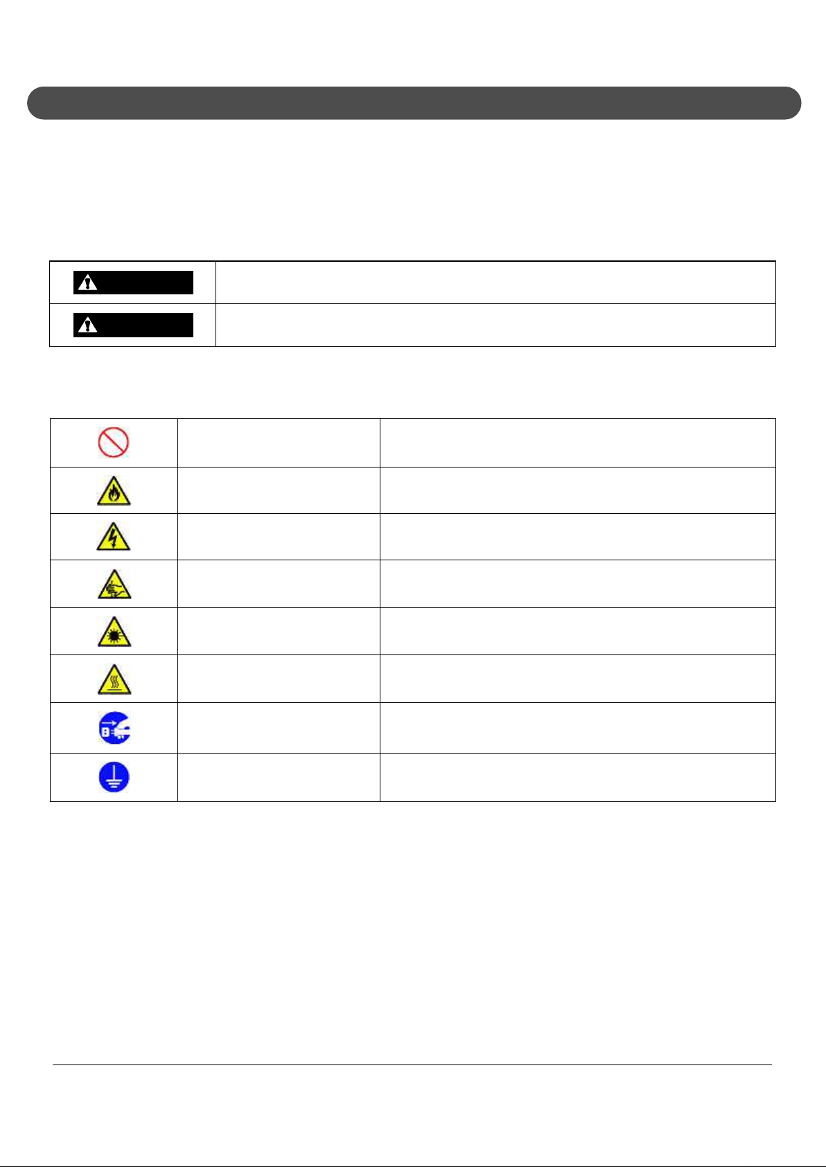
The following symbols indicate a potential for personal injury or property damage due to an
improper operation.
Prohibited Indicates a prohibited action.
Attention to fire Indicates there is a risk of fumes and/or a fire.
Attention to electric shock Indicates there is a risk of electric shock.
Attention to personal injury Indicates there is a risk of personal injury.
Attention to laser beam Indicates there is a risk of loss of eyesight due to laser beam.
Attention to high temperature
Indicates there is a risk of product failure due to high
temperature.
Unplug the power cord. Indicates an instruction to unplug the power cord.
Connect grounding conductor. Indicates an instruction to connect the grounding conductor.
NEC ShieldPRO FC-N21S Ruggedised Notebook Computer
User’s Guide 0318-00002 Ver. 2.0 Dec 2008 – Page i
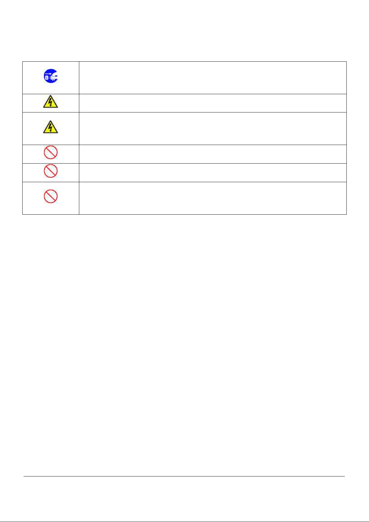
1.1. General Warnings
If smoke, odour, noise, or abnormal heat is generated, immediately turn off ShieldPRO and
disconnect the power plug from the outlet. Remove the battery, if installed, after making sure
that you can do so safely. Using the computer in such conditions may cause a fire, burns, and/or
electric shock.
Do not hold the power plug while your hands are wet. Failure to follow this warning may cause
an electric shock.
Do not touch the computer during a thunderstorm.
Do not touch the computer, connected cables, and peripheral devices, or install/remove such
devices when a thunderstorm is approaching. Failure to follow this warning may cause an
electric shock due to lightning.
Do not disassemble or modify the product. Failure to follow this warning may cause an electric
shock, fumes, and/or fire.
Do not place the product in a fire, apply excess heat, or short-circuit the terminal. Failure to
follow this warning may cause a fire, and/or explosion.
Do not intentionally remove or damage any of the warning labels. Warning labels are attached to
components to inform the user that a hazardous situation may arise when using the product. If
you find any labels totally/partially removed or illegible due to damage, contact your ShieldPRO
supplier.
NEC ShieldPRO FC-N21S Ruggedised Notebook Computer
User’s Guide 0318-00002 Ver. 2.0 Dec 2008 – Page ii

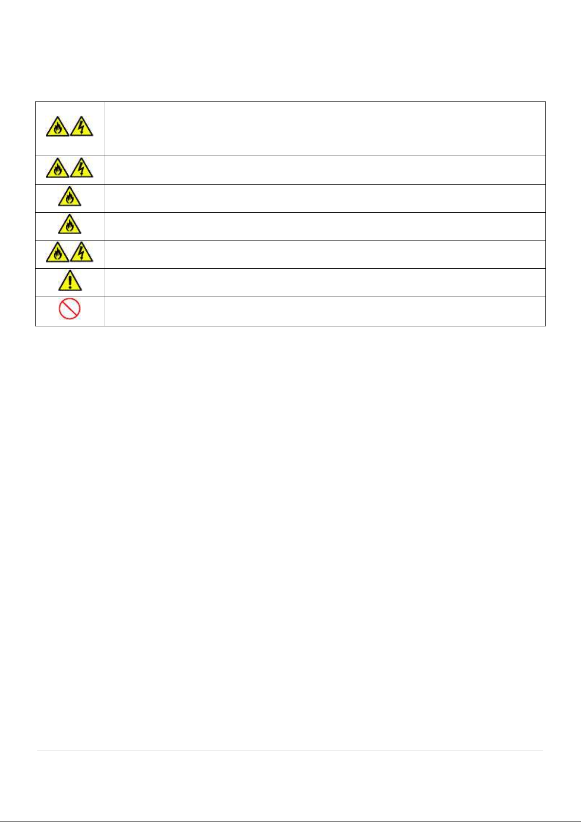
1.2. Installation Environment Warnings
The following precautions pertain to environmental requirements. Failure to follow these warnings
may cause an electric shock, fumes, and/or fire.
Do not install or use the product in a location where medical vapor is emitted into the air, and avoid
contact between medical substances and ShieldPRO.
Do not use the product in an environment where any liquid (such as water), metals, or other foreign
substances may come in contact with the product.
Do not use or store the product in a place of extremely high or low temperature or extreme
temperature change.
NEC ShieldPRO FC-N21S Ruggedised Notebook Computer
User’s Guide 0318-00002 Ver. 2.0 Dec 2008 – Page iii

1.3. Power Supply and Power Cord Warnings
The AC adapter and AC cord are designed for use only with this product. The AC adapter may be
damaged if it is connected to a device other than this product.
The AC cord used with this product must be approved by an acceptable accredited agency
responsible for evaluation in the country where the AC cord will be installed.
Do not connect the power cord to an outlet that has an illegal number of connections. The electric
current exceeding the rated flow overheats the outlet, which may cause a fire.
The AC cord shipped with this product can only be used for 240 VAC. Do not connect this AC cord to
an outlet of which rating exceeds 250 VAC. Failure to follow this instruction may cause a fire and/or
electric shock.
Make sure the power plug is inserted into the outlet as far as possible. A halfway inserted power plug
may cause a fire and/or an electric shock.
Do not use this product if dust has accumulated on the AC power cord plug. If dust accumulates on
the power plug, an electrical discharge occurs between plug pins and it may cause a fire.
Always hold the plug of the AC cord upon its removal. Do not pull the cord. Breaking the wire may
cause a fire.
Do not use the AC cord if the plug blades are unstable. Poor connection may cause a fire.
Do not pull the AC cord forcibly or put heavy objects on it. Breaking the wire may cause a fire and/or
electric shock.
The drip-proof and dust-proof performance of IP54 do not apply to the AC adapter and AC cord.
Follow instructions described below when handling them to prevent fume, fire, and/or electric shock
to occur.
Do not drop or cause impact to the AC adapter.
Do not use the power cord when bent or twisted.
Do not forcedly bend the base of the power cord.
Do not put any heavy object on the AC adapter or power cord.
Do not wrap the AC adapter with cloth or other material.
Do not use the AC adapter in a place where splashing of water or other liquids may occur.
Do not use the AC cord and/or AC adapter if it is damaged.
Do not put the AC adapter near a thermal appliance.
Do not put the AC adapter in a place that experiences extreme temperature changes (for example,
near the exhaust port of an air conditioner).
Do not use the AC adapter near flammable gas and/or combustible substances.
Do not put the AC adapter in a place where steam is generated (for example, in a kitchen or near a
humidifier).
Do not use the AC adapter in a place where salinity (for example, sea breeze) or a corrosive gas (for
example, hot springs) is generated.
Use only the specified AC adapter and AC cord. Never attempt to disassemble or modify the AC
adapter. Doing so may cause an electric shock, smoke, and/or fire.
NEC ShieldPRO FC-N21S Ruggedised Notebook Computer
User’s Guide 0318-00002 Ver. 2.0 Dec 2008 – Page iv
1.4. Battery Warnings
The provided battery is designed to be used with this product only. Do not use the battery for any
other device.
In addition, do not use any other battery than the provided battery for this product. Failure to follow
this instruction may cause a fire and/or electric shock.
To charge the battery, install it in ShieldPRO or use dedicated charger (FC-N013: option). Charging
using another method may cause a fire and/or electric shock.
Do not short-circuit the battery. Doing so may cause a fire.
Do not heat the battery or place it in or near flame. Doing so may cause a fire.
Do not disassemble the battery. Doing so may cause a fire and/or an electric shock.
Dispose of used batteries according to the instructions.
Do not drop the battery. Doing so may cause damage to the battery.
NEC ShieldPRO FC-N21S Ruggedised Notebook Computer
User’s Guide 0318-00002 Ver. 2.0 Dec 2008 – Page v

1.5. Miscellaneous Warnings
Any users with implantable cardiac pacemakers should distance this product from the pacemaker by
30 cm or more. Pacemakers may be influenced by radio waves radiated from this product.
In any areas where medical agencies prohibit wireless LAN from being used, turn off the power of
this product or disable the wireless LAN feature. Failure to follow this instruction may affect the
function of medical equipment.
If traveling in an aeroplane where the use of wireless and electronic devices is prohibited, turn off the
power of this product or disable the wireless LAN feature. This product may influence electronic
devices.
If this product causes radio disturbance to other devices during the use of a wireless feature, disable
the wireless feature or stop using this product. Failure to follow this instruction may influence other
devices and cause malfunction.
NEC ShieldPRO FC-N21S Ruggedised Notebook Computer
User’s Guide 0318-00002 Ver. 2.0 Dec 2008 – Page vi

1.6. Caution During Operation
Take care when installing or removing the peripherals to avoid injury to hands or fingers.
The bottom face of this product gets hot during and immediately after operation. Do not place it on
your lap for a long time to avoid low-temperature burn injury.
NEC ShieldPRO FC-N21S Ruggedised Notebook Computer
User’s Guide 0318-00002 Ver. 2.0 Dec 2008 – Page vii

1.7. Miscellaneous Cautions
After turning off the power of this product, wait for five seconds or longer before you turn the power
on again. Turning on the power just after turn-off without a certain interval may cause a malfunction
or fault to occur.
To remove the AC adapter, first remove the plug from the power outlet and then disconnect the plug
from the product. Removing the plugs in the reserve order may cause the AC adapter and/or this
product to be damaged.
Avoid handling the product while eating, drinking or smoking.
A floppy disk contaminated with cigarette ash may cause data read/write error or damage to the
floppy disk drive.
Do not use floppy disks and/or CD-ROMs that are dirty.
Using a floppy disk dirty with sand, dust, and/or liquid (for example, water) may cause failure of the
drive.
When relocating the product, pay attention not to give an excessive shock and/or vibration as defined
in environmental specification. If a shock and/or vibration given to the product exceed the
environmental specification, the internal hard disk drive and/or other components may be damaged.
Notes on storage
Unplug the AC cord from the outlet if you do not use the product for an extended period.
Do not leave any object made of rubber or vinyl in contact with the product. Do not wrap the product
in a vinyl bag or leave rubber bands or the like on the product. Doing so may cause transformation of
the product surface.
NEC ShieldPRO FC-N21S Ruggedised Notebook Computer
User’s Guide 0318-00002 Ver. 2.0 Dec 2008 – Page viii

NOTES:
1) No part of this manual may be reproduced in any form without the prior written permission of NEC Australia.
2) The contents of this manual may be revised without prior notice.
3) All efforts have been made to ensure the accuracy of all information in this manual. If you notice any part that
is unclear, incorrect, or omitted in this manual, contact your ShieldPRO supplier.
4) NEC assumes no liability arising from the use of this product, nor any liability for incidental or consequential
damage arising from the use of this manual regardless of Item (3) above.
5) This product is not intended for use or control in the facilities or devices concerning human lives, including
medical devices, nuclear facilities and devices, aeronautics and space devices, transportation facilities and
devices; and facilities and devices requiring high reliability. NEC assumes no liability for any accident
resulting in personal injury, death, or property damage if this product has been used in the above conditions.
To use this product in facilities and devices and/or control systems, take sufficient considerations for safety
such as redundant configuration, fire delay measures, and malfunction prevention measures.
6) This product (including software) is intended to be sold and used only in Australia. NEC Australia does not
support maintenance service and technical support in any country outside Australia.
7) The components used in this product may be changed with equivalent components to maintain long-term
supply.
8) The operating system (Windows® XP) pre-installed in the internal hard disk drive and CD-ROMs provided
with the product can be used for this product only.
9) It is piracy to replicate a part or whole of software, or distribute it without permission of the copyright owner.
10) Pay attention not to lose the license label of installed operating system (COA label) that is attached to this
pre-installed model.
11) The data you have saved on the hard disk drive, floppy disk, and/or CD-ROM are excluded from the warranty
of this product. Be sure to make a backup copy of user data.
12) It is recommended to install anti-virus software and update the virus definition file on a regular basis.
NEC ShieldPRO FC-N21S Ruggedised Notebook Computer
User’s Guide 0318-00002 Ver. 2.0 Dec 2008 – Page ix

1.8. Exporting Notice
This model of ShieldPRO (including software) is Australian market specific, and has not been
certified for standards of any other country. NEC Australia assumes no liability arising from the use
of this product in any other country than Australia. In addition, no maintenance, service and
technical support for this product are provided in any other country than Australia.
NEC ShieldPRO FC-N21S Ruggedised Notebook Computer
User’s Guide 0318-00002 Ver. 2.0 Dec 2008 – Page x

1.9. EMC Notice
EMC compliance has been attained using cables (except the LAN cable) of a length of less than 3
metres. (EMC directive 89/336/EEC).
NEC ShieldPRO FC-N21S Ruggedised Notebook Computer
User’s Guide 0318-00002 Ver. 2.0 Dec 2008 – Page xi

1.10. VCCI Notice
This product is VCCI Class B information technology equipment conforming to the reference level
of the Voluntary Control Council for Interference by Information Technology Equipment (VCCI). If
used near a radio, TV and/or wireless device, this product may cause poor reception. Use this
product according to descriptions in "Notes on Use" and relevant sections.
The wireless LAN (5 GHz) can only be used indoors due to relevant radio laws.
The radio wave output of this product is lower than the reference value defined in "Radio
Frequency-Exposure Protection Standard (RCR STD-38)" by Association of Radio Industries and
Businesses.
NEC ShieldPRO FC-N21S Ruggedised Notebook Computer
User’s Guide 0318-00002 Ver. 2.0 Dec 2008 – Page xii

1.11. Federal Communications Commission (FCC) Notice
NOTE: This equipment has been tested and found to comply with the limits for a Class B digital device,
pursuant to Part 15 of the FCC Rules.
These limits are designed to provide reasonable protection against harmful interference in a residential
installation.
This equipment generates, uses and can radiate radio frequency energy and, if not installed and used in
accordance with the instructions, may cause harmful interference to radio communications.
There is no guarantee that interference will not occur in any installation.
If this equipment does cause harmful interference to radio or television reception, which can be
determined by turning the equipment off and on, the user is encouraged to try to correct the
interference by one or more of the following measures:
Reorient or relocate the receiving antenna.
Increase the distance between the equipment and receiver.
Connect the equipment into an outlet on a circuit different from that to which the receiver is
connected.
Consult the dealer or an experienced radio/TV technician for help.
NEC ShieldPRO FC-N21S Ruggedised Notebook Computer
User’s Guide 0318-00002 Ver. 2.0 Dec 2008 – Page xiii

1.12. Wireless LAN Notice
The following safety precautions should be observed:
Do not touch or move the antenna while the unit is transmitting or receiving.
Do not hold any component containing the radio (such as the antenna) in close proximity or
touching any exposed parts of the body, especially the face or eyes, while transmitting.
Do not operate the radio or attempt to transmit data unless the antenna is connected to avoid
damage to the radio module.
1.12.1. Use in Specific Environments
The use of wireless devices in hazardous locations is limited by the constraints posed by the
safety directors of such environments.
The use of wireless devices on aeroplanes is governed by the Federal Aviation Administration
(FAA).
The use of wireless devices in hospitals is restricted to the limits set forth by each hospital.
1.12.2. Antenna Use
In order to comply with FCC RF exposure limits, low gain integrated antennas should be located
at a minimum distance of 20 cm (8 inches) or more from the body of all persons.
High-gain, wall-mount, or mast-mount antennas are designed to be professionally installed and
should be located at a minimum distance of 30 cm (12 inches) or more from the body of all
persons.
Please contact your professional installer, VAR, or antenna manufacturer for proper installation
requirements.
1.12.2.1. Explosive device proximity warning
WARNING
Do not operate a portable transmitter (such as a wireless network device) near unshielded
blasting caps or in an explosive environment unless the device has been modified to be
qualified for such use.
1.12.2.2. Antenna warning
WARNING
WARNING
To comply with the FCC and ANSI C95.1 RF exposure limits, it is recommended for the
equipment installed in ShieldPRO, that the antenna for this device be installed at a distance
of at least 20 cm (8 inches) from all persons and that the antenna must not be co-located or
operating in conjunction with any other antenna or radio transmitter. It is recommended that
the user limit exposure time if the antenna is positioned closer than 20 cm (8 inches).
ShieldPRO series products are not designed for use with high-gain directional antennas.
Use of such antennas with these products is illegal.
NEC ShieldPRO FC-N21S Ruggedised Notebook Computer
User’s Guide 0318-00002 Ver. 2.0 Dec 2008 – Page xiv

1.12.2.3. Use on aircraft caution
CAUTION
1.12.2.4. Local restrictions on 802.11a, 802.11b, and 802.11g radio usage
CAUTION
Regulations of the FCC and FAA prohibit airborne operation of radio-frequency wireless
devices because their signals could interfere with critical aircraft instruments.
Due to the fact that the frequencies used by 802.11a, 802.11b and 802.11g wireless LAN
devices may not yet be harmonised in all countries, 802.11a, 802.11b, and 802.11g products
are designed for use only in specific countries, and are not allowed to be operated in
countries other than those of designated use.
As a user of these products, you are responsible for ensuring that the products are used only
in the countries for which they were intended and for verifying that they are configured with
the correct selection of frequency and channel for the country of use.
1.12.2.5. USA: Federal Communications Commission (FCC)
This device complies with Part 15 of the FCC Rules. Operation of the device is subject to the
following two conditions:
This device may not cause harmful interference.
This device must accept any interference that may cause undesired operation.
NOTE: The radiated output power of the wireless network device is far below the FCC radio frequency exposure
limits.
Nevertheless, the wireless network device should be used in such a manner that the potential for human contact
during normal operation is minimised.
To avoid the possibility of exceeding the FCC radio frequency exposure limits, you should keep a distance of at
least 20 cm between you (or any other person in the vicinity) and the antenna that is built into the computer.
1.12.2.6. Europe frequency bands
2.400 - 2.4835 GHz (Europe ETSI)
5.15 - 5.35 GHz and 5.47-5.725 GHz (Europe ETSI)
Low band 5.25 - 5.35 GHz is for indoor use only
5.47 - 5.725 GHz is current not allowed in Czech Republic and France.
NEC ShieldPRO FC-N21S Ruggedised Notebook Computer
User’s Guide 0318-00002 Ver. 2.0 Dec 2008 – Page xv

1.13. Telephone Line Connection
Federal Communications Commission (FCC)
This equipment complies with Part 68 of the FCC rules. On the bottom of ShieldPRO is a label
that contains among other information, the FCC registration number and ringer equivalence
number (REN) for this equipment. If requested, this information must be provided to the
telephone company.
Any plug or jack used to connect this equipment to the premises wiring and telephone network
must comply with the applicable FCC Part 68 rules and requirements adopted by the ACTA.
The REN is used to determine the number of devices that may be connected to a telephone
line. Excessive RENs on a telephone line may result in the devices not ringing in response to an
incoming call. In most but not all areas, the sum of RENs should not exceed five (5.0). To be
certain of the number of devices that may be connected to a line, as determined by the total
RENs, contact the local telephone company.
If this NEC equipment causes harm to the telephone network, the telephone company will notify
you in advance that temporary discontinuance of service may be required. If advance notice
isn't practical, the telephone company will notify the customer as soon as possible. If the
equipment is causing harm to the telephone network, the telephone company may request that
you disconnect the equipment until the problem is resolved. Also, you will be advised of your
right to file a complaint with the FCC if you believe it is necessary.
If trouble is experienced with this NEC equipment, and for repair or warranty information, please
contact your ShieldPRO supplier.
The telephone company may make changes in its facilities, equipment, operations or
procedures that could affect the operation of the equipment. If this happens, the telephone
company will provide advance notice in order for you to make necessary modifications to
maintain uninterrupted service.
Connection to party line service is subject to state tariffs. Contact the state public utility
commission, public service commission or corporation commission for information.
There are no user serviceable parts contained in this equipment.
NEC ShieldPRO FC-N21S Ruggedised Notebook Computer
User’s Guide 0318-00002 Ver. 2.0 Dec 2008 – Page xvi

1.14. Transfer to Third Party
The following must be observed when you transfer (or sell) the product or software provided with
the product to a third party. In addition, be sure to include this User's Guide when you transfer (or
sell) the product to a third party.
1.14.1. About data on the hard disk drive
Be sure to take appropriate measures not to disclose important data (for example, customers'
information or companies' management information) on the hard disk drive to be transferred to any
third parties.
Data appears to be erased when you empty the "Recycle Bin" or execute the "format" command of
the operating system. However, the actual data remains written on the hard disk drive. Data not
erased completely may be restored by special software and used for unexpected purposes.
It is strongly recommended that the Hard Disk Erase feature in BIOS SETUP menu or the software
or service for data erasure (both available at stores) should be used in order to avoid the trouble
explained above.
NEC shall not assume any liability for such data disclosure caused by your failure to take the
necessary measures.
1.14.2. Provided software
To transfer or sell any software that comes with the product to a third party, the following
requirements must be satisfied:
All provided software must be transferred and no backup copies must be retained.
Transfer requirements listed in the "Software License Agreement" that comes with the software
must be satisfied.
Software that is not approved for transfer must be uninstalled before transferring the product.
1.14.3. Disposal of Consumed Parts and Equipment
Consult with your ShieldPRO supplier for disposal of the product and optional devices.
NEC ShieldPRO FC-N21S Ruggedised Notebook Computer
User’s Guide 0318-00002 Ver. 2.0 Dec 2008 – Page xvii
2. Text Conventions
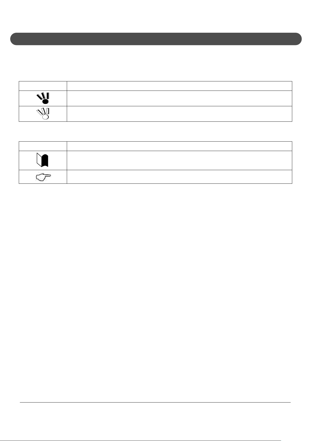
2.1. Symbols in the Text
This manual uses the following symbols:
Symbol Description
If the handling information is ignored, the product may be damaged, software used in the
This manual also uses the following symbols.
Symbol Description
product may malfunction, and/or the data created by the user may be corrupted.
If the handling information is ignored, the product may be damaged and/or software used in the
product may not operate normally.
Supplement of the text.
Reference page.
NEC ShieldPRO FC-N21S Ruggedised Notebook Computer
User’s Guide 0318-00002 Ver. 2.0 Dec 2008 – Page xviii

2.2. Typographical Conventions Concerning Keyboard Operation
Keyboard keys are represented in bold-faced letters.
Example: Press Enter to exit.
When several keys are combined, it is indicated using the plus sign (+), press and hold the first key,
press another key, and then release all the keys. An illustration may be used to indicate keys.
NEC ShieldPRO FC-N21S Ruggedised Notebook Computer
User’s Guide 0318-00002 Ver. 2.0 Dec 2008 – Page xix

3. Contents
1. Notes on Use ............................................................................................................................. i
1.1. General Warnings ............................................................................................................ ii
1.2. Installation Environment Warnings ..................................................................................iii
1.3. Power Supply and Power Cord Warnings....................................................................... iv
1.4. Battery Warnings ............................................................................................................. v
1.5. Miscellaneous Warnings ................................................................................................. vi
1.6. Caution During Operation ...............................................................................................vii
1.7. Miscellaneous Cautions ................................................................................................. viii
1.8. Exporting Notice .............................................................................................................. x
1.9. EMC Notice .................................................................................................................... xi
1.10. VCCI Notice ....................................................................................................................xii
1.11. Federal Communications Commission (FCC) Notice .................................................... xiii
1.12. Wireless LAN Notice ......................................................................................................xiv
1.12.1. Use in Specific Environments ................................................................................ xiv
1.12.2. Antenna Use .......................................................................................................... xiv
1.12.2.1. Explosive device proximity warning ................................................................... xiv
1.12.2.2. Antenna warning ................................................................................................ xiv
1.12.2.3. Use on aircraft caution ........................................................................................ xv
1.12.2.4. Local restrictions on 802.11a, 802.11b, and 802.11g radio usage...................... xv
1.12.2.5. USA: Federal Communications Commission (FCC) ........................................... xv
1.12.2.6. Europe frequency bands ..................................................................................... xv
1.13. Telephone Line Connection ...........................................................................................xvi
1.14. Transfer to Third Party .................................................................................................. xvii
1.14.1. About data on the hard disk drive .......................................................................... xvii
1.14.2. Provided software .................................................................................................. xvii
1.14.3. Disposal of Consumed Parts and Equipment ......................................................... xvii
2. Text Conventions .................................................................................................................. xviii
2.1. Symbols in the Text ..................................................................................................... xviii
2.2. Typographical Conventions Concerning Keyboard Operation .......................................xix
3. Contents ................................................................................................................................. xx
4. System Overview ...................................................................................................................... 1
NEC ShieldPRO FC-N21S Ruggedised Notebook Computer
User’s Guide 0318-00002 Ver. 2.0 Dec 2008 – Page xx

4.1. Hardware Specification .................................................................................................... 1
4.2. Selection Menu Table ...................................................................................................... 6
4.3. Environmental Specification (Main Unit) .......................................................................... 7
4.4. Exterior View ................................................................................................................... 9
4.5. Names and Features of ShieldPRO .............................................................................. 10
4.5.1. Inner panels ............................................................................................................ 10
4.5.2. Outside sections ..................................................................................................... 12
4.6. Installation Notes ........................................................................................................... 14
4.6.1. Notes on installation location .................................................................................. 14
4.6.2. Notes on operation .................................................................................................. 14
4.6.3. Notes on operational environment .......................................................................... 14
4.6.4. Notes on cable connections .................................................................................... 14
4.6.5. Notes on handling of HDD ...................................................................................... 15
4.6.6. Notes on handling of devices sensitive to magnetism (including floppy disks) ........ 15
4.7. Use of ShieldPRO in an Industrial Environment ............................................................ 16
4.7.1. Dust-proof and Drip-proof Performance .................................................................. 16
4.7.1.1. Dust-proof performance ...................................................................................... 16
4.7.1.2. Drip-proof performance ....................................................................................... 16
4.7.2. Operating Temperature Range ............................................................................... 16
4.7.3. Shock Resistance ................................................................................................... 17
4.7.4. Continuous Operation of ShieldPRO for Long Periods ........................................... 17
4.8. Cleaning ........................................................................................................................ 18
4.8.1. Preparation for Cleaning ......................................................................................... 18
4.8.2. Cleaning Components............................................................................................. 18
4.8.2.1. Main unit, touch pad and keyboard ..................................................................... 18
4.8.2.2. LCD display ........................................................................................................ 18
4.8.2.3. Power cord and AC adapter................................................................................ 18
4.8.2.4. Fingerprint sensor (option) .................................................................................. 18
4.9. Carriage and Storage of ShieldPRO .............................................................................. 19
4.9.1. Storage of ShieldPRO ............................................................................................. 19
4.10. Disposal of Devices ....................................................................................................... 20
5. Using the ShieldPRO Computer ............................................................................................. 21
5.1. Opening and Closing the LCD Display Panel ................................................................ 21
5.1.1. Opening the LCD Display Panel ............................................................................. 21
NEC ShieldPRO FC-N21S Ruggedised Notebook Computer
User’s Guide 0318-00002 Ver. 2.0 Dec 2008 – Page xxi

5.1.2. Closing the LCD Display Panel ............................................................................... 21
5.2. Tablet Mode ................................................................................................................... 22
5.2.1. Changing to Tablet Mode ........................................................................................ 22
5.3. Power Functions ............................................................................................................ 23
5.3.1. Power States and Operations ................................................................................. 23
5.3.1.1. Power states ....................................................................................................... 23
5.3.1.2. Power Lamp........................................................................................................ 24
5.3.1.3. Switching ShieldPRO on and off ......................................................................... 24
5.3.1.4. Suspend (standby) and resume .......................................................................... 26
5.3.1.5. Hibernate state and recovering from hibernate state .......................................... 29
5.4. AC Adapter .................................................................................................................... 32
5.4.1. Installing the AC Adapter ........................................................................................ 32
5.5. Battery ........................................................................................................................... 34
5.5.1. Installing and Replacing the Battery ........................................................................ 34
5.5.2. Charging Battery ..................................................................................................... 35
5.5.3. Refreshing the Battery ............................................................................................ 36
5.5.4. Checking Remaining Battery Level ......................................................................... 37
5.5.5. Recycling Batteries ................................................................................................. 38
5.5.6. Low Battery Charge Level ....................................................................................... 39
5.5.6.1. Reduction in remaining battery level during battery operation ............................ 39
5.5.6.2. Configuring ShieldPRO for low battery operation ............................................... 39
5.5.7. Notes on Batteries................................................................................................... 39
5.6. Tablet Buttons ............................................................................................................... 41
5.6.1. Tablet Button Operations ........................................................................................ 41
5.6.2. Label Pasting Area .................................................................................................. 41
5.6.3. Changing Button Assignment .................................................................................. 41
5.7. Keyboard ....................................................................................................................... 42
5.7.1. English Keyboard .................................................................................................... 42
5.7.1.1. Uses of hot key [Fn] ............................................................................................ 42
5.7.1.2. Typing the euro symbol ...................................................................................... 43
5.8. Touch Pad ..................................................................................................................... 45
5.8.1. Touch Pad Settings ................................................................................................. 45
5.9. Touch Panel .................................................................................................................. 47
5.9.1. Touch Panel Settings .............................................................................................. 47
NEC ShieldPRO FC-N21S Ruggedised Notebook Computer
User’s Guide 0318-00002 Ver. 2.0 Dec 2008 – Page xxii

5.9.2. Touch Panel Calibration .......................................................................................... 48
5.10. Display Feature ............................................................................................................. 49
5.11. Display Resolution ......................................................................................................... 50
5.11.1. Adjusting Screen Display ........................................................................................ 50
5.11.2. Connecting an External Monitor .............................................................................. 51
5.12. Communication Feature ................................................................................................ 52
5.12.1. Modem .................................................................................................................... 52
5.12.1.1. Connecting ShieldPRO with a phone line ........................................................... 52
5.12.1.2. Modem Settings .................................................................................................. 52
5.12.2. LAN ......................................................................................................................... 53
5.12.2.1. Connecting ShieldPRO to network ..................................................................... 53
5.12.2.2. LAN Settings ....................................................................................................... 53
5.12.2.3. Remote power-on feature ................................................................................... 54
5.12.3. Wireless LAN .......................................................................................................... 55
5.12.3.1. Notes on security when using wireless LAN products ........................................ 55
5.12.3.2. Security enabled by ShieldPRO .......................................................................... 56
5.12.3.3. Activating the Wireless LAN................................................................................ 57
5.12.4. Serial Port ............................................................................................................... 58
5.13. USB (USB 2.0) .............................................................................................................. 59
5.13.1. Connecting USB devices to ShieldPRO .................................................................. 59
5.13.2. Removing USB devices from ShieldPRO ................................................................ 59
5.13.3. Connect/disconnect-proof enhanced connector ...................................................... 60
5.14. PC Card (PCMCIA)........................................................................................................ 61
5.14.1. Supporting CardBus ................................................................................................ 61
5.14.2. Installing a PC Card in ShieldPRO .......................................................................... 61
5.14.3. Removing a PC Card from ShieldPRO ................................................................... 61
5.15. SD Card ......................................................................................................................... 63
5.15.1. Data Transfer Rate.................................................................................................. 63
5.15.2. Notes on Handling and Storage of an SD Card ...................................................... 63
5.15.2.1. Do not take the following actions with an SD card: ............................................. 63
5.15.2.2. Do not place SD card in the following places: ..................................................... 63
5.15.3. SD use in different ShieldPRO states ..................................................................... 63
5.15.4. SD Data Protection ................................................................................................. 64
5.15.5. Installing or Removing SD Card in/from SD Card Slot ............................................ 64
NEC ShieldPRO FC-N21S Ruggedised Notebook Computer
User’s Guide 0318-00002 Ver. 2.0 Dec 2008 – Page xxiii

5.15.5.1. Inserting SD card into SD card slot ..................................................................... 64
5.15.5.2. Removing SD card from SD card slot ................................................................. 64
5.16. Microphone Input Terminal ............................................................................................ 65
5.17. Output Terminal Common to Line and Head Phone ...................................................... 65
5.18. Built-in Speaker ............................................................................................................. 65
5.19. I/O Interfaces ................................................................................................................. 66
5.19.1. PCMCIA (PC CARD) interface ................................................................................ 66
5.19.2. Modem .................................................................................................................... 68
5.19.3. LAN interface (1000BASE-T) .................................................................................. 68
5.19.4. AC adapter jack ...................................................................................................... 68
5.19.5. Headphone Output Interface ................................................................................... 68
5.19.6. Microphone Input Interface ..................................................................................... 68
5.19.7. Analog RGB Interface ............................................................................................. 69
5.19.8. Serial Interface (COM1) .......................................................................................... 70
5.19.9. USB Interface (USB 1/2/3) ...................................................................................... 70
5.19.10. SD Interface ............................................................................................................ 70
6. Setting BIOS ........................................................................................................................... 71
6.1. BIOS SETUP Utility ....................................................................................................... 71
6.1.1. Settings on BIOS SETUP Utility .............................................................................. 71
6.1.2. Running/Exiting BIOS SETUP Utility ....................................................................... 71
6.1.2.1. Starting ............................................................................................................... 71
6.1.2.2. Automatic Save changes and Exit ...................................................................... 72
6.1.2.3. Exit menu ............................................................................................................ 72
6.1.3. Loading the BIOS SETUP Defaults ......................................................................... 73
6.2. Menus ............................................................................................................................ 74
6.2.1. Main Menu .............................................................................................................. 74
6.2.1.1. System time ........................................................................................................ 74
6.2.1.2. System date ........................................................................................................ 74
6.2.1.3. Primary master ................................................................................................... 74
6.2.1.4. Processor settings .............................................................................................. 74
6.2.1.5. System memory .................................................................................................. 74
6.2.1.6. Extended memory ............................................................................................... 74
6.2.1.7. Language ............................................................................................................ 74
6.2.2. Primary Master Submenu ....................................................................................... 75
NEC ShieldPRO FC-N21S Ruggedised Notebook Computer
User’s Guide 0318-00002 Ver. 2.0 Dec 2008 – Page xxiv

6.3. Advanced Menu ............................................................................................................. 76
6.3.1. Advanced Menu Configuration ................................................................................ 76
6.3.1.1. PCI configuration ................................................................................................ 76
6.3.1.2. I/O device configuration ...................................................................................... 76
6.3.1.3. Summary screen ................................................................................................. 76
6.3.1.4. Silent boot ........................................................................................................... 76
6.3.1.5. QuickBoot mode ................................................................................................. 76
6.3.1.6. Fn/Left Ctrl key replacement ............................................................................... 77
6.3.1.7. Tablet button ....................................................................................................... 77
6.3.1.8. DMI event logging ............................................................................................... 77
6.3.2. PCI Configuration Submenu ................................................................................... 78
6.3.3. I/O Device Configuration Submenu ......................................................................... 79
6.3.4. Tablet Button Submenu .......................................................................................... 81
6.4. Security Menu ................................................................................................................ 83
6.4.1. Security ................................................................................................................... 83
6.4.1.1. Supervisor password .......................................................................................... 83
6.4.1.2. User password .................................................................................................... 83
6.4.1.3. Set supervisor password..................................................................................... 83
6.4.1.4. Set user password .............................................................................................. 84
6.4.1.5. User password protection ................................................................................... 84
6.4.1.6. Password on boot ............................................................................................... 85
6.4.1.7. Network boot setting ........................................................................................... 85
6.4.1.8. HardDisk security ................................................................................................ 85
6.4.1.9. No-execute memory protection ........................................................................... 87
6.4.1.10. Security chip configuration .................................................................................. 88
6.4.2. Clearing BIOS Passwords ....................................................................................... 88
6.4.2.1. Clearing passwords by BIOS SETUP Utility ....................................................... 88
6.5. Power Management Menu ............................................................................................. 90
6.5.1. Power Management Configuration .......................................................................... 90
6.6. System Menu ................................................................................................................. 92
6.7. Boot Menu ..................................................................................................................... 94
6.7.1. Boot Order Configuration ........................................................................................ 94
7. Installing OS and Applications ................................................................................................ 95
7.1. Windows XP Pre-installed Model ................................................................................... 95
NEC ShieldPRO FC-N21S Ruggedised Notebook Computer
User’s Guide 0318-00002 Ver. 2.0 Dec 2008 – Page xxv

7.1.1. Microsoft Windows XP Service Pack 2 ................................................................... 95
7.1.2. Changing owner and/or organisation by modifying registry ..................................... 96
7.2. Windows HDD Configuration ......................................................................................... 96
7.3. Repairing System .......................................................................................................... 97
7.3.1. Starting Windows XP in safe mode ......................................................................... 97
7.3.2. Repairing system to [Last Known Good Configuration] ........................................... 98
7.3.3. Repairing system by using [System Restore] .......................................................... 98
7.3.4. Using Recovery Disks to reload system .................................................................. 99
7.3.4.1. Reloading from Recovery Disk Procedure .......................................................... 99
7.3.4.2. Recovering settings made after purchase after reloading ................................. 101
7.3.5. Re-installing Windows XP ..................................................................................... 101
7.3.5.1. Re-installing Windows Procedure ..................................................................... 102
7.3.5.2. Change to keyboard or mouse of different key layout ....................................... 105
7.3.5.3. Recovering settings made after purchase after re-installation .......................... 106
7.4. Installing Supplied Drivers and Applications ................................................................ 107
7.4.1. Chipset drivers ...................................................................................................... 107
7.4.1.1. Supported operating systems ........................................................................... 107
7.4.1.2. Installation procedure ....................................................................................... 107
7.4.2. VGA Drivers .......................................................................................................... 107
7.4.2.1. Supported operating systems ........................................................................... 107
7.4.2.2. Installation procedure ....................................................................................... 107
7.4.2.3. Deletion procedure ........................................................................................... 108
7.4.3. Audio Drivers ........................................................................................................ 108
7.4.3.1. Supported operating systems ........................................................................... 108
7.4.3.2. Installation procedure ....................................................................................... 109
7.4.3.3. Deletion procedure ........................................................................................... 109
7.4.4. Modem Drivers ...................................................................................................... 109
7.4.4.1. Supported operating systems ........................................................................... 109
7.4.4.2. Installation procedure ....................................................................................... 109
7.4.4.3. Deletion procedure ........................................................................................... 110
7.4.5. LAN Drivers ........................................................................................................... 110
7.4.5.1. Supported operating systems ........................................................................... 110
7.4.5.2. Installation procedure ....................................................................................... 110
7.4.5.3. Deletion procedure ........................................................................................... 111
NEC ShieldPRO FC-N21S Ruggedised Notebook Computer
User’s Guide 0318-00002 Ver. 2.0 Dec 2008 – Page xxvi

7.4.6. Wireless LAN Drivers ............................................................................................ 111
7.4.6.1. Supported operating systems ........................................................................... 111
7.4.6.2. Installation procedure ....................................................................................... 111
7.4.6.3. Deletion procedure ........................................................................................... 112
7.4.7. Touch Panel Drivers.............................................................................................. 112
7.4.7.1. Supported operating systems ........................................................................... 112
7.4.7.2. Installation procedure ....................................................................................... 112
7.4.7.3. Deletion procedure ........................................................................................... 113
7.4.8. Touch Pad Drivers ................................................................................................ 113
7.4.8.1. Supported operating systems ........................................................................... 113
7.4.8.2. Installation procedure ....................................................................................... 114
7.4.8.3. Deletion procedure ........................................................................................... 114
7.4.9. Infineon Security Platform ..................................................................................... 114
7.4.9.1. Overview ........................................................................................................... 114
7.4.9.2. Supported operating systems ........................................................................... 114
7.4.9.3. BIOS setting procedure .................................................................................... 115
7.4.9.4. Installation procedure ....................................................................................... 115
7.4.9.5. Starting procedure ............................................................................................ 116
7.4.9.6. Usage ............................................................................................................... 116
7.4.9.7. Deletion procedure ........................................................................................... 116
7.4.10. FC Button Setting Tool .......................................................................................... 117
7.4.10.1. Overview ........................................................................................................... 117
7.4.10.2. Supported operating systems ........................................................................... 117
7.4.10.3. Installation procedure ....................................................................................... 117
7.4.10.4. Deletion procedure ........................................................................................... 118
7.4.10.5. Usage ............................................................................................................... 118
7.4.10.6. Start procedure ................................................................................................. 118
7.4.11. Fingerprint Authentication Utility (not provided in standard product) ..................... 118
7.4.11.1. Overview ........................................................................................................... 119
7.4.11.2. Supported operating systems ........................................................................... 119
7.4.11.3. Installation procedure ....................................................................................... 119
7.4.11.4. Usage ............................................................................................................... 119
7.4.11.5. Deletion procedure ........................................................................................... 119
8. Security ................................................................................................................................. 121
NEC ShieldPRO FC-N21S Ruggedised Notebook Computer
User’s Guide 0318-00002 Ver. 2.0 Dec 2008 – Page xxvii

8.1. Setting a Password on BIOS SETUP Utility ................................................................. 121
8.1.1. Security Password for BIOS SETUP Utility ........................................................... 121
8.1.2. HDD Password ..................................................................................................... 121
8.2. I/O Lock Feature .......................................................................................................... 122
8.3. Login Password ........................................................................................................... 123
8.4. Security Chip ............................................................................................................... 124
8.5. Fingerprint Authentication Password ........................................................................... 125
8.6. Antitheft Lock ............................................................................................................... 126
9. Options ................................................................................................................................. 127
9.1. Extended RAM Board FC-UG-M013 (1GB) ................................................................. 127
9.1.1. Installation Procedure of Extended RAM Board .................................................... 127
9.1.2. Extended RAM Board Removal Procedure ........................................................... 129
9.1.3. Extended RAM Confirmation Procedure ............................................................... 130
9.2. Hard Disk Drive FC-HD60KN (Standard)..................................................................... 131
9.2.1. Specification of HDD (standard) ............................................................................ 131
9.2.2. HDD Removal Procedure ...................................................................................... 131
9.2.3. HDD Installation Procedure ................................................................................... 132
9.3. Hard Disk Drive for Wide Temperature Range FC-HD40KN ....................................... 134
9.3.1. Specification of HDD (standard) ............................................................................ 134
9.4. Spare Battery FC-N011 (Standard Type) .................................................................... 135
9.4.1. Specification of FC-N011 ...................................................................................... 135
9.4.2. Handling FC-N011 ................................................................................................ 135
9.4.2.1. Handling of battery in use or charging .............................................................. 136
9.4.2.2. Handling of battery in storage ........................................................................... 136
9.4.2.3. Battery life ......................................................................................................... 136
9.5. AC Adapter FC-N012................................................................................................... 137
9.5.1. Specification of AC Adapter .................................................................................. 137
9.6. Battery Charger FC-N013 (Not available in Australia) ................................................. 138
9.6.1. Specification of Battery Charger ........................................................................... 138
10. Maintenance ......................................................................................................................... 139
10.1. Troubleshooting ........................................................................................................... 139
10.1.1. Flowchart .............................................................................................................. 139
10.1.2. Actions Taken to Solve Problems (Tips) ............................................................... 140
10.1.2.1. Take proper actions calmly ............................................................................... 140
NEC ShieldPRO FC-N21S Ruggedised Notebook Computer
User’s Guide 0318-00002 Ver. 2.0 Dec 2008 – Page xxviii

10.1.2.2. Write down message on screen if displayed ..................................................... 140
10.1.2.3. Try to identify the problem ................................................................................ 140
10.1.2.4. Boot ShieldPRO in safe mode .......................................................................... 140
10.1.2.5. Use system information .................................................................................... 140
10.1.2.6. Recover BIOS settings to factory defaults ........................................................ 141
10.1.2.7. Restore system ................................................................................................. 142
10.1.2.8. Contact Supplier ............................................................................................... 142
10.1.3. Troubleshooting Q&A ............................................................................................ 142
10.1.3.1. Smoking, heat generation, noise and cable disconnection ............................... 142
10.1.3.2. Power-on .......................................................................................................... 142
10.1.3.3. Battery .............................................................................................................. 145
10.1.3.4. Display .............................................................................................................. 145
10.1.3.5. Hardware devices ............................................................................................. 147
10.1.3.6. HDD .................................................................................................................. 147
10.1.3.7. File storage ....................................................................................................... 148
10.1.3.8. Keyboard, mouse and touch pad ...................................................................... 149
10.1.3.9. Network (LAN) .................................................................................................. 149
10.1.3.10. Wireless LAN .................................................................................................... 151
10.1.3.11. PC card ............................................................................................................. 153
10.1.3.12. Power management .......................................................................................... 153
10.1.3.13. Software............................................................................................................ 155
10.1.3.14. Sound ............................................................................................................... 155
10.1.3.15. External CD-R/W with DVD-ROM drives .......................................................... 156
10.1.3.16. External floppy disk drives ................................................................................ 156
10.1.3.17. Passwords ........................................................................................................ 157
10.1.3.18. Miscellaneous ................................................................................................... 158
11. Appendices ........................................................................................................................... 159
11.1. Interrupt Request (IRQ) Table ..................................................................................... 159
11.2. Outside Dimensions..................................................................................................... 160
11.2.1. ShieldPRO ............................................................................................................ 160
11.2.2. Spare Battery FC-N011 ......................................................................................... 162
11.2.3. AC Adapter FC-N012 ............................................................................................ 164
11.2.4. Hard Disk Drive FC-HD60KN ............................................................................. 165
NEC ShieldPRO FC-N21S Ruggedised Notebook Computer
User’s Guide 0318-00002 Ver. 2.0 Dec 2008 – Page xxix


4. System Overview
4.1. Hardware Specification
Item ShieldPRO FC-N21S (Note 1)
CPU (Note 2) Intel Core Solo U1400 ultra-low voltage processor
(Extended Intel SpeedStep technology (Note 3) installed [1.20 GHz])
Cache memory Primary 32KB for instruction/32KB for data (built in CPU)
Secondary 2.048KB (built in CPU)
System bus 533 MHz (memory bus: 400 MHz)
Chip set Mobile Intel 945GM Express chip set ICH7-M
Security chip (Note 4) Conforming to TPM V.1.2
Memory (Note 5) 2GB max. (Note 6)
2 SO-DIMM slots
DDR2-SDRAM (PC2-3200 (DDR2-400))
Display
element
(Note 7)
Graphic accelerator Built in mobile Intel 945GM Express chip set
Display feature
Input device
Video RAM 128MB max. (use of main memory)
Resolution and display colors LCD: 1024×768 dots (16.77 million colors (Note 11))
Floppy disk drive (not included)
CD-ROM type drive (not included)
Fixed disk drive Standard 60GB (Serial ATA specification) or
(Note 13)
Auxiliary storage
Keyboard (Note 14) Standard English keyboard Key pitch: 17.55 mm
12.1-in. TFT color LCD display (XGA) with touch panel (Note 8)
Stuck pixels of
LCD (Note 9)
0.0005% or less
(Dual display (Note 10), smoothing, and screen rotation features
available)
External monitor: 1600×1200 dots max. (Note 12) (16.77 million
colors (Note 11))
Customised Order Optional 40GB (wide temperature range and Ultra
ATA specification)
Key stroke: 2.4 mmbacklit keyboard : 2.0mm
Customised Order Options:
a/ Backlit keyboard
b/ Keyboard cover
Pointing device Touch pad
NEC ShieldPRO FC-N21S Ruggedised Notebook Computer
User’s Guide 0318-00002 Ver. 2.0 Dec 2008 – Page 1

Item ShieldPRO FC-N21S (Note 1)
Tablet button 10 (5 buttons and 5 Tb + buttons) (Note 15)
USB (Note 16) 3 ports (including 1 connect/disconnect-proof enhanced port),
USB2.0 compatible
Serial 1 DB9 connector of 115,200 bps max. (male)
Display Mini DB15 connector (female) (for analog RGB monitor)
Network Built-in LAN 1 RJ45 LAN connector (1000BASE-T / 100BASE-TX / 10BASE-T)
Wireless LAN Conforming to IEEE802.11a/b/g (Note 17)
WEP [encryption key length: 64/128 bits (user setting key length:
40/104 bits)], WPA-PSK (TKIP/AES) and WPA2-PSK (AES)
compatible
Interface (Note 13)
Built-in modem (Note 18) 1 RJ11 modular connector
Modem: 56k bps max. (Note 19) (V.90/V.92 compatible)
FAX: 14.4k bps max. (V.17 compatible)
Sound feature Built-in PCM record/replay feature and monaural speaker
Microphone input (stereo, mini jack) and output common to
headphone/line (stereo, mini jack)
PC card slot (Notes 13and 20) 1 Type I/II slot (Type III unavailable) conforming to PC Card
Standard and compatible with CardBus
SD card slot (Notes 13and 20) 1 slot
Security feature Security software included as standard (Note 21)
Finger print
sensor
Customised Order Option: Built-in type (line type)
Authentication by fingerprint at OS logon or release of screen saver
Power management Automatic or arbitrary settings enabled (including CPU control, hard
disk control, monitor power saving, suspend (standby) feature and
hibernation)
Power supply Computer
Operating voltage: 16 VDC ±5
Battery
(Notes 22 and 23)
Standard type: Operating period - 8 hours, charging time (in
power-on state – about 3 hours and in power off states - 3 hours)
Weight: 0.3 kg
AC adapter Input: 100 to 240 VAC ±10%, 1.5A, 50/60 Hz
Output: 16V DC, 4.5A
Conforming standard Suitable to RoHS direct and conforming to VCCI Class B.
Designed based on EMC direct (EN55022 and EN61000-6-2) (Note
24) and low voltage direct (EN60950-1) (Note 24) standards. Power
design based on standard UL60950-1
NEC ShieldPRO FC-N21S Ruggedised Notebook Computer
User’s Guide 0318-00002 Ver. 2.0 Dec 2008 – Page 2

Item ShieldPRO FC-N21S (Note 1)
ShieldPRO Power consumption 15 W in normal use (50 W maximum.)
Energy efficiency
(Power saving achievement rate)
Target year: 2005 (Note 25), S division 0.00025 (AAA)
Target year: 2007 (Note 26), I division 0.0020 (A)
Outside dimension 284(W) × 255(D) × 48(H) mm (excluding projections and bumper)
Weight Approx 2.5 kg (including standard battery)
Installed OS Microsoft Windows XP Professional (Service Pack 2)
NEC ShieldPRO FC-N21S Ruggedised Notebook Computer
User’s Guide 0318-00002 Ver. 2.0 Dec 2008 – Page 3

NOTES:
1. See "4.2 Selection Menu Table" for type names and numbers.
2. ShieldPRO includes a control feature enabling the CPU to operate dynamically depending on use in
different environments and under different loads.
3. In any Operating System environment other than the one preinstalled, the expanded IntelSpeedStep
feature may be unavailable.
4. The security chip is unavailable to any Operating System other than the preinstalled Windows XP
Professional.
5. The standard ShieldPRO is provided with 1GB memory board. Expanded RAM board FC-UG-M013 (1GB,
PC2-4200) is available.
6. Only one slot is available for expanded RAM. Hence the maximum RAM is the standard 1GB plus one
expanded RAM card of 1GB in the second slot.
7. The LCD display is manufactured using extremely precise technology. However, dot drops (such as tiny
black points and red, blue or green points) may appear on a part of the screen. In addition, colour and/or
brightness irregularities may appear depending on view angles. These are caused by characteristics of
LCD displays and do not indicate any defects.
8. The touch panel feature is unavailable if the USB Controller is disabled in BIOS Setup
9. The base dot drop rate is calculated in sub-pixels according to the standard of ISO13406-2.
10. An external display screen may be different from the LCD display of ShieldPRO.
11. 16.77 million colour display is accomplished by the dithering feature of graphic accelerator.
12. The resolution and number of colours available will depend on the resolution and refresh rate of the
connected display. The LCD display on ShieldPRO can display the same screen as an external display
connected to ShieldPRO. However, if the enlarged display feature is not used, displayed data may not
extend over the entire screen of the external display.
13. Evaluate any commercial product that will be used for ShieldPRO to confirm that the product is valid.
14. The standard English keyboard is only available for the Windows XP Professional (Service Pack 2)
pre-installed model.
15. Each tablet button can be set to launch any application loaded in ShieldPRO.
16. Any software using peripherals connected to ShieldPRO must use the USB interface.
17. ShieldPRO is equipped with a wireless LAN module obtaining Wi-Fi standard of the Wi-Fi Alliance. The
communication speed and distance may be affected by various factors including connected devices, radio
wave environment, surrounding obstacles, installation environment, user situation, or application software.
OS. IEEE802.11b/g (2.4 GHz) is not compatible with IEEE802.11a (5 GHz). The wireless LAN is not
suitable for Super AG and Atheros XR (extended Range). The wireless LAN (5 GHz) conforms to
IEEE802.11a The wireless LAN (5 GHz) can only be used indoors due to relevant radio laws.
NEC ShieldPRO FC-N21S Ruggedised Notebook Computer
User’s Guide 0318-00002 Ver. 2.0 Dec 2008 – Page 4

i) Disable the wireless LAN feature when abroad as it may conflict with related laws in international
countries
18. The communication speed may vary depending on line status. The built-in fax modem can only be used
with the general subscriber phone line.
19. The maximum data transfer rate is 56k bps for data receive, or 33.6k bps for data transmission.
20. PC and SD cards are not included with ShieldPRO.
21. Refer to "7 Installing OS and Applications" for supporting Operating System of the attached security
software.
22. The battery operating and charging times may be different from those specified depending on situations in
which the battery pack is used. The battery pack is a consumable. If the long driving mode is selected on
the BIOS Setup Menu, the CPU operation performance is in the low mode.
23. The battery operating time is measured based on the JEITA battery operation time measurement method
(Ver. 1.0). The time varies depending on operating environments, brightness of LCD display and system
settings.
24. These standards are required for CE marking.
25. The energy consumption efficiency is obtained by dividing the power consumption measured based on the
measurement method defined by the Rationalization in Energy Use Law (target year: 2005) by the
composite theory performance defined by the Rationalization in Energy Use Law. Power saving
achievement rates A, AA and AAA means achievement rates equal to or larger than 100% and less than
200%, equal to or larger than 200% and less than 500% and equal to or larger than 500%, respectively.
26. The energy consumption efficiency is obtained by dividing the power consumption measured based on the
measurement method defined by the Rationalization in Energy Use Law (target year: 2007) by the
composite theory performance defined by the Rationalization in Energy Use Law. Power saving
achievement rates A, AA and AAA means achievement rates equal to or larger than 100% and less than
200%, equal to or larger than 200% and less than 500% and equal to or larger than 500%, respectively.
NEC ShieldPRO FC-N21S Ruggedised Notebook Computer
User’s Guide 0318-00002 Ver. 2.0 Dec 2008 – Page 5

4.2. Selection Menu Table
Series title Selection menu
Base unit Keyboard OS
FC-N21S
CPU
Intel Core
Solo Processor
Ultra-low voltage
ver.
U1400 (1.2 GHz)
Memory (2 slots)
PC card (1 slot)
SD card (1 slot)
[B]
Standard keyboard
Part name
[Y]
Windows XP
Professional
(Service Pack2)
English ver.
preinstalled
(Note 1)
Memory
capacity
[0]
1GB
(1GB × 1)
[5]
2GB
(1GB × 2)
Model name
Disk drive and
battery
[B]
Standard HDD
(SerialATA spec.,
60GB)
Standard battery
Wireless LAN
and
fingerprint
authentication
[1]
Wireless LAN:
Yes
Fingerprint
authentication:
No
[2]
Wireless LAN:
No
Fingerprint
authentication:
No
Part number
NOTES: 1) The key assignments are based on the Standard English keyboard layout.
* The part number of ShieldPRO can be found on the base of the unit.
The Windows XP pre-installed model of ShieldPRO already has Microsoft Windows XP
Professional Operating System (Service Pack 2) installed. Note that deleting and down-grading
of Service Packs is disabled.
First partition: 20GB (NTFS) (Software already installed at shipment occupies about 5GB in the
first partition.)
Second partition: Remaining memory (NTFS)
NEC ShieldPRO FC-N21S Ruggedised Notebook Computer
User’s Guide 0318-00002 Ver. 2.0 Dec 2008 – Page 6

4.3. Environmental Specification (Main Unit)
Item
Temperature Operating 5 to 45 ºC
Storage -40 to 70ºC
Evaluation standard IEC 68-2-1,2,14 / MIL-STD-810F, Method 501.4, 502.4
Humidity Operating 5 to 95% RH (without condensation)
Storage 5 to 95% RH (without condensation)
Evaluation standard IEC 68-2-30 / MIL-STD-810F, Method 507.4
Altitude Operating 15,000 ft (4,572 m)
Storage 40,000 ft (12,190 m)
Change rate 2,000 ft/min (609.6 m/min)
Evaluation standard IEC 68-2-13 / MIL-STD-810F, Method 500.4
Shock resistance
(Note 1)
Vibration resistance
(Note 1)
Operating 147 m/s2, 11 ms, half sinusoidal wave
Storage 490 m/s2, 11 ms, half sinusoidal wave
Evaluation standard IEC 68-2-27 / MIL-STD-810F, Method 516.5
Operating [Sinusoidal wave] 0.075 mm (0-P) in frequency range 10 to 55 Hz
Condition
Installation of standard hard disk drive and battery
9.8 m/s2 (0-P) in frequency range 55 to 500 Hz
Storage [Sinusoidal wave] 0.15 mm (0-P) in frequency range 10 to 55 Hz
19.6 m/s2 (0-P) in frequency range 55 to 500 Hz
[Random wave] 0.04G2/Hz in frequency range 20 to 1000 Hz
–6 dB/Octave in frequency range 1000 to 2000 Hz
Operating Sinusoidal wave: IEC68-2-6
Storage Sinusoidal wave: IEC68-2-6
Random wave: MIL-STD-810F, Method 514.5 Category 24
FIGURE 514.5C-17
Dust proof and drip
proof
Evaluation
standard
Operating IP54
Storage IP54
Evaluation standard IEC 529 / MIL-STD-810F
IEC: Abbreviation for International Electrotechnical Commission.
MIL: Abbreviation for Military Specifications and Standards.
NOTE 1: The vibration resistance of ShieldPRO does not assure that it has sufficient strength against resonance
generated when the frequency of added vibration is close to the natural frequency of ShieldPRO.
* ShieldPRO may not operate continuously under the described environmental conditions in which ShieldPRO is
installed.
NEC ShieldPRO FC-N21S Ruggedised Notebook Computer
User’s Guide 0318-00002 Ver. 2.0 Dec 2008 – Page 7

In addition, if ShieldPRO is equipped with one or more NEC or commercial options, the most severe
environmental condition among those for ShieldPRO and the options is applied.
While ShieldPRO is stored in a place at ambient temperature of 0ºC or lower, the clock in ShieldPRO may drift.
Set the clock the next time ShieldPRO is used.
NEC ShieldPRO FC-N21S Ruggedised Notebook Computer
User’s Guide 0318-00002 Ver. 2.0 Dec 2008 – Page 8

4.4. Exterior View
ShieldPRO can be used as a notebook or tablet PC.
ShieldPRO has several characteristics including its light weight, various security features and
installation of touch panel to enhance user-friendliness.
The hard disk drive, expanded RAM board and battery pack can be replaced, and are accessible
on the base of ShieldPRO.
NEC ShieldPRO FC-N21S Ruggedised Notebook Computer
User’s Guide 0318-00002 Ver. 2.0 Dec 2008 – Page 9

4.5. Names and Features of ShieldPRO
(10)
(8)
(1)
(5)
(2)
(6)
(7)
(9)
(3)
(11) (12) (13)
4.5.1. Inner panels
No. Name Description Reference page
(4)
(1) LCD display
(with touch panel)
(2) Power lock switch
(3) Power switch Allows you to turn on/off power.
(4) Fingerprint sensor Reads fingerprint (Customised Order Option). 118
(5) Tablet buttons
(6) Keyboard 42
(7) Touch pad 42
(8)
Wireless LAN
antenna
12.1-in. TFT LCD display. 49
Locks the power switch to prevent the switch from
being set unintentionally (enabled by BIOS setting).
Allows the security, screen rotation and LCD brightness
adjustment features to be executed directly.
You can assign any key codes to these buttons through
BIOS.
Used for wireless LAN. 55
90
41
NEC ShieldPRO FC-N21S Ruggedised Notebook Computer
User’s Guide 0318-00002 Ver. 2.0 Dec 2008 – Page 10

No. Name Description Reference page
(9) Power lamp
While power is supplied to ShieldPRO, the lamp
illuminates or blinks in several colors as described
below:
Solid green: Power-on status
Blinking green: Suspend (standby) status
Solid yellow: Low battery level (7% to 10% of
the full level)
Blinking yellow: Low battery level in suspend
(standby) state (7% to 10% of the full level)
Solid orange: Extremely low battery level (0%
to 6% of the full level)
Blinking orange: Extremely low battery level in
suspend (standby) state (0% to 6% of the full
level)
OFF: Power-off or not in use
(10) Battery charge lamp Indicates battery status.
OFF: Discharging during battery refresh,
or full discharged and no AC adapter
or full charge completed
Solid orange: Charging
Blinking orange: Occurrence of error
23
35
(11) Disk access lamp
(12) Caps lock key lamp
(13)
Numeric lock key
lamp
Lit in green indicates built-in HDD activity. -
Indicates whether the caps lock feature is enabled or
42
disabled.
Solid green: Caps lock feature enabled
OFF: Caps lock feature disabled
Press the Caps Lock button to toggle between
the two states
Indicates whether the numeric lock feature is enabled
42
or disabled.
Solid green: Numeral lock feature enabled
OFF: Numeral lock feature disabled
Press the Fn+ Num Lk button to toggle
between the two states
NEC ShieldPRO FC-N21S Ruggedised Notebook Computer
User’s Guide 0318-00002 Ver. 2.0 Dec 2008 – Page 11

4.5.2. Outside sections
[Left side view]
(1)
(2) (3) (4)
[Rear view]
[Top view]
(7)
(5)
[Bottom view]
(6)
(8)
(9)
(10)
[Right side view]
(11)
(12)
(13) (14) (15) (16)
No. Name Description
(17) (18)
(19)
Reference
page
(1) Power terminal Connects with the AC adapter. 32
(2) Microphone terminal (stereo)
(3)
Output terminal common to line
and headphone (stereo)
Connects with a commercial microphone (stereo and
mini jack type)
Outputs sounds to a commercial audio device or
headphone (stereo and mini jack type)
(4) Antitheft lock Connects with a commercial security cable. 126
(5) External monitor output connector Connects with an external analog RGB monitor. 51
(6) Serial connector Connects with a serial device such as a modem. 58
(7) LCD display fixing lock Locks the LCD display. 21
(8) Stylus storage area Stores the attached stylus.
(9) Battery storage area Stores the attached battery. 34
(10) Disk drive storage area Stores disk drives (installed). 131
(11) Expanded memory storage area Stores expanded RAM board. 127
(12) Built-in speaker (monaural) Monaural speaker for sound replay. 65
65
65
NEC ShieldPRO FC-N21S Ruggedised Notebook Computer
User’s Guide 0318-00002 Ver. 2.0 Dec 2008 – Page 12

USB connector (1)
(13)
(Connect/disconnect-proof
Connects with a USB device (USB2.0 available). 59
enhanced type)
(14) USB connector (2) Connects with a USB device (USB2.0 available). 59
(15) USB connector (3) Connects with a USB device (USB2.0 available). 59
(16) SD card slot Accepts an SD card. 63
(17) PC card slot Accepts a PC card (PCMCIA of type II) 61
(18) Modular connector for phone line Connects with phone line (2 Wire). 52
(19) LAN (1000BASE-T) connector
Connects with LAN
(1000BASE-T/100BASE-TX/10BASE-T) cable.
53
NEC ShieldPRO FC-N21S Ruggedised Notebook Computer
User’s Guide 0318-00002 Ver. 2.0 Dec 2008 – Page 13

4.6. Installation Notes
This section provides notes on how to install and connect ShieldPRO and peripherals.
4.6.1. Notes on installation location
Install ShieldPRO in a place where it can be operated properly. See "4.7 Use of ShieldPRO in an
Industrial Environment" for details.
4.6.2. Notes on operation
1. Before connecting or disconnecting cables to/from peripherals, make sure that power to
ShieldPRO is OFF. Connecting or disconnecting cables to/from a peripheral with ShieldPRO
ON may cause a malfunction or fault to occur.
2. After turning off ShieldPRO, wait for five seconds or longer before turning the power on
again. Turning on the power immediately after turning it off may cause a malfunction or fault
to occur.
3. Clean ShieldPRO periodically.
4.6.3. Notes on operational environment
1. ShieldPRO is VCCI Class B information technology equipment (or information equipment
mainly intended to be used in household environments) conforming to the reference level of
the Voluntary Control Council for Interference by Information Technology Equipment (VCCI).
2. If ShieldPRO is used near a radio, TV and/or wireless device, ShieldPRO may cause poor
reception. Also a device generating intense magnetic field located near ShieldPRO may
cause ShieldPRO to operate improperly. If this occurs, move ShieldPRO away from the
device.
3. To use ShieldPRO in an industrial environment, always ensure ShieldPRO meets the
conditions described in "4.3 Environmental Specification (Main Unit)".
4.6.4. Notes on cable connections
1. Use cables authorised by NEC.
2. To connect peripheral devices to ShieldPRO, use appropriate cables with connector shapes
and signal alignments meeting those of ShieldPRO and the peripheral devices.
3. Do not pull cables forcefully or put objects on cables.
4. Install peripheral devices at locations where cables connected to the devices may not be
pulled excessively. Avoid using ShieldPRO if cables are stretched and/or objects are put on
cables.
5. Insert connectors securely. Inserting connectors loosely may cause ShieldPRO and
peripheral devices not to operate at all or operate deficiently.
NEC ShieldPRO FC-N21S Ruggedised Notebook Computer
User’s Guide 0318-00002 Ver. 2.0 Dec 2008 – Page 14

4.6.5. Notes on handling of HDD
Hard disk drives are precision devices.
ShieldPRO has buffer materials to protect the hard disk drive, however, note the following to protect
data:
Do not apply shocks and vibrations exceeding those defined in the environmental
specification to ShieldPRO.
Ensure the hard disk drive is not subject to strong shocks when the drive is removed from
ShieldPRO.
4.6.6. Notes on handling of devices sensitive to magnetism
(including floppy disks)
A magnet to sense opening or closing of the LCD display panel is
contained at the upper left corner of the panel.
The magnet may destroy data saved in magnetic media. Do not put
devices sensitive to magnetism (including floppy disks) close to the
magnet.
Magnet
NEC ShieldPRO FC-N21S Ruggedised Notebook Computer
User’s Guide 0318-00002 Ver. 2.0 Dec 2008 – Page 15

4.7. Use of ShieldPRO in an Industrial Environment
4.7.1. Dust-proof and Drip-proof Performance
ShieldPRO is designed to have high seal performance to prevent liquid and dust from getting into it
from external sources.
ShieldPRO can be used outdoors if it rains and can be handled with wet and/or dirty hands.
With optional dust-proof and drip-proof cables (FC-N015/FC-N016), ShieldPRO has drip-proof and
dust-proof performance conforming to IP54 when connecting with one or more external devices.
4.7.1.1. Dust-proof performance
Protection class IP5x means that a device cannot completely avoid entry of dust but that some dust
does not interrupt the defined operations and safety of the device.
To make dust-proof performance effective, the connector, HDD, battery and memory covers must
be closed properly.
4.7.1.2. Drip-proof performance
Protection class IPx4 means that a device is not affected by spray from any angle (by a spray
nozzle).
Ensure ShieldPRO is not left wet for a long period. If it is wet, wipe and dry with a cloth.
To ensure drip-proof performance, the connector, HDD, battery and memory covers must be closed
properly.
Always operate ShieldPRO with its base facing downward.
Use optional drip-proof cables to connect to the power connector and the LAN and serial ports. For other
ports, use connectors with their covers closed securely.
4.7.2. Operating Temperature Range
The ‘wide temperature type’ ShieldPRO can operate in the temperature range between -20ºC and
50ºC while of the standard ShieldPRO operates in the temperature range between 5ºC and 45ºC.
To allow ShieldPRO to be used in the wide temperature range (–20 to 50ºC), the main unit, HDD
and battery all should be in the wide temperature range.
In a high temperature environment, the main unit may become hot. If so, wear gloves so that hands
do not contact the unit directly.
To suppress heat generation, the performance of ShieldPRO may be restricted automatically.
In an environment at a low temperature, the battery driving time is shortened.
When ShieldPRO is in the tablet mode or the battery charging state, the AC adapter should be used in
NEC ShieldPRO FC-N21S Ruggedised Notebook Computer
User’s Guide 0318-00002 Ver. 2.0 Dec 2008 – Page 16

ambient temperature range 5 to 40ºC.
In addition, the LCD display may respond slower than normal.
4.7.3. Shock Resistance
The chassis of ShieldPRO is made of magnesium die-cast alloy and equipped with a hard disk
drive designed for shock resistance.
ShieldPRO has been designed to endure a drop test from a height of 90 cm to a plywood or
concrete floor.
The shock resistance of ShieldPRO does not guarantee that no damage or faults will occur.
If ShieldPRO is damaged by shock, it may have reduced dust-proof and drip-proof performance as well as
shock resistance. Accordingly, it is recommended to repair ShieldPRO immediately when damaged.
4.7.4. Continuous Operation of ShieldPRO for Long Periods
If ShieldPRO is operated continuously for a long period, the lifespan of parts in ShieldPRO may be
reduced. Therefore, NEC may charge for the repair of ShieldPRO within the warranty period if
subjected to continuous operation for a long period.
If a hard disk drive (HDD) is used, rest the HDD periodically to reduce deterioration caused by
continuous operation.
To rest the hard disk drive, the power management may be set by the OS (Windows) to halt the
HDD automatically if access to the hard disk does not occur for a certain period:
Period set at shipment: 30 minutes (when ShieldPRO is connected to AC power)
Recommended period: 3 minutes (when ShieldPRO is connected to AC power)
NEC ShieldPRO FC-N21S Ruggedised Notebook Computer
User’s Guide 0318-00002 Ver. 2.0 Dec 2008 – Page 17

4.8. Cleaning
4.8.1. Preparation for Cleaning
Use dry and clean cloths made of soft materials to clean ShieldPRO if dirt is minimal.
To clean more stubborn dirt, use clean cloths soaked with water or lukewarm water and wrung to
remove excess water.
Do not use volatile organic solvents including thinner and benzene or chemical rags to clean
ShieldPRO. Failure to follow this instruction may cause the exterior casting to be damaged or a fault to
occur.
Do not pour excessive amounts of water on ShieldPRO directly. Failure to follow this instruction may
cause ShieldPRO to be damaged.
4.8.2. Cleaning Components
4.8.2.1. Main unit, touch pad and keyboard
1. Wipe the main unit, touch pad and keyboard with the prepared cloths.
2. If dust is in the gaps in the keyboard, remove it by using commercial computer cleaner.
3. If dust cannot be removed, contact your ShieldPRO supplier.
4.8.2.2. LCD display
Wipe the LCD display with a soft, dry and clean cloth. Do not use a wet cloth.
4.8.2.3. Power cord and AC adapter
If ShieldPRO is left connected to the power cord and/or AC adapter, dust and dirt may accumulate
on the connected plugs. Remove the dirt periodically.
4.8.2.4. Fingerprint sensor (option)
The fingerprint sensor is touched directly and therefore may pick up dirt from fingers and may not
operate properly
Wipe the fingerprint sensor lightly with a soft, dry and clean cloth to remove dirt.
Do not use volatile organic solvents including thinner and benzene and chemical rags to clean the
fingerprint sensor.
Do not use a sharp object such as a ballpoint pen to clean the fingerprint sensor.
NEC ShieldPRO FC-N21S Ruggedised Notebook Computer
User’s Guide 0318-00002 Ver. 2.0 Dec 2008 – Page 18

4.9. Carriage and Storage of ShieldPRO
Follow the procedure below if ShieldPRO is to be carried or stored:
Back up important data stored in the hard disk.
Close and latch all the covers when you transport ShieldPRO.
1. Turn off the power of ShieldPRO.
2. Disconnect the AC adapter.
To pull out a cord, be sure to hold the plug. Pulling the cord itself may cause a break in the cord
3. Remove all cables connected to ShieldPRO.
4. Remove the battery.
5. Package ShieldPRO securely so that it can not be damaged. Minimise shock and vibration
during transportation.
from the plug and electric shock or fire may occur.
4.9.1. Storage of ShieldPRO
Remove the battery from ShieldPRO if it will be stored for a long period.
Do not store the battery in a place where the temperature may exceed 60ºC. This can cause
deterioration of the battery.
Store the battery in the following temperature ranges:
-20 to 60ºC for storage for a month or shorter
-20 to 45ºC for storage for three months or shorter
-20 to 20ºC for storage for a year or shorter
Do not leave the battery for three months or longer without recharging.
NEC ShieldPRO FC-N21S Ruggedised Notebook Computer
User’s Guide 0318-00002 Ver. 2.0 Dec 2008 – Page 19

4.10. Disposal of Devices
For disposal of ShieldPRO, hard disk drives and options, contact your ShieldPRO supplier.
See "5.5.5 Recycling Batteries" for disposal of the battery.
Do no put the battery close to fire or soak it with water. Failure to follow this instruction may cause the
battery to catch on fire, fume or explode.
NEC ShieldPRO FC-N21S Ruggedised Notebook Computer
User’s Guide 0318-00002 Ver. 2.0 Dec 2008 – Page 20

5. Using the ShieldPRO Computer
5.1. Opening and Closing the LCD Display Panel
5.1.1. Opening the LCD Display Panel
1. Pull up latch A (refer to picture below) and unhook latch B.
2. Open the LCD display panel.
Pull up latch A
Unlatch latch B
Latch B
Latch A
5.1.2. Closing the LCD Display Panel
1. Align the guide supports on the base unit to the guides on the LCD display panel and close
the panel.
Guides on display panel
Guide supports on base unit
2. Pull up latch A.
3. Hook latch B onto the LCD display panel and push down latch A to securely close.
Hook latch B on the position.
If latch B is hooked improperly, check if the guide on the LCD display is aligned with the guide support on
the base unit.
NEC ShieldPRO FC-N21S Ruggedised Notebook Computer
User’s Guide 0318-00002 Ver. 2.0 Dec 2008 – Page 21

5.2. Tablet Mode
5.2.1. Changing to Tablet Mode
1. Open the LCD display panel to a 90º angle.
2. Rotate the LCD display panel clockwise by 180º.
Do not rotate the LCD display panel clockwise
by more than 180º. Do not rotate the LCD
display panel anti-clockwise.
3. Align the guides on the display panel with the guide
supports on the base unit and close the panel with the
LCD display facing upward.
4. Pull up latch A.
5. Hook latch B onto the LCD display panel and push down latch A to securely close the display
panel.
If latch B is hooked incorrectly, check if the guide on the LCD display is aligned with the guide support on
the base unit.
NEC ShieldPRO FC-N21S Ruggedised Notebook Computer
User’s Guide 0318-00002 Ver. 2.0 Dec 2008 – Page 22

5.3. Power Functions
This section describes how to switch ShieldPRO on and off, and how to use the power saving
features including suspend (standby) and hibernate states.
If you do not follow the correct procedure for switching ShieldPRO on and off, and into and out of power
saving modes you may lose data and programs, and possibly damage the computer.
5.3.1. Power States and Operations
5.3.1.1. Power states
The power states of ShieldPRO are as follows:
power-off,
power-on,
suspend (standby), and
hibernate.
Power-off or
hibernate
state
Turn on power
Turn off power
Return from
hibernate state
Enter into
hibernate state
Power-on
state
Suspend
(Standby)
Resume
Suspend
(standby) state
Power-off state
In the power-off state, ShieldPRO is completely shut down.
Power-on state
In the power-on state, ShieldPRO is in normal operation mode.
Suspend (standby) state
In suspend (standby) state, working data is temporarily saved in memory. Power consumption is
suppressed by suspending the hard disk drive and other devices, and changing the LCD display
into power saving state. The only power used is that needed to keep the computer's state and
working data in memory.
Because working data is saved in memory, ShieldPRO can immediately return to the original state
when the computer is returned from suspend (standby) state.
NEC ShieldPRO FC-N21S Ruggedised Notebook Computer
User’s Guide 0318-00002 Ver. 2.0 Dec 2008 – Page 23

Some operating systems do not support suspend (standby) state.
Hibernate state
Hibernate state is similar to suspend (standby) state, but after the computer's state is saved to the
hard disk, power is switched off completely to the computer. When the computer is switched on
again, ShieldPRO returns to its original state. It takes longer to return from hibernate state than it
does from suspend (standby) state. Hibernate state consumes less power than suspend (standby)
state.
Some operating systems do not support hibernate state.
5.3.1.2. Power Lamp
The power lamp’s display changes depending on power states, as shown in the following table.
Supply of power Power state Power lamp
Supply of AC power Power-off OFF
Power-on Solid green
Suspend (standby) state Blinking green
Hibernate state OFF
No supply of AC power Remaining battery level: 11% or larger Solid green
Remaining battery level: 7 to 10% Solid yellow
Remaining battery level: 0 to 6% Solid orange
5.3.1.3. Switching ShieldPRO on and off
Switching On ShieldPRO
To switch on ShieldPRO from the power-off state
Wait for five seconds or longer after power-off before turning the power on.
1. Turn off peripheral devices.
NEC ShieldPRO FC-N21S Ruggedised Notebook Computer
User’s Guide 0318-00002 Ver. 2.0 Dec 2008 – Page 24

Some peripheral devices may only be recognised properly if their power is switched on before switching on
ShieldPRO.
Refer to the User Guides of peripheral devices for more information.
2. Press the power switch of ShieldPRO.
Power lock release switch
After switching ShieldPRO on, it may take up to 10 seconds for the start-up screen to appear.
For details of the operation of the power lock release switch, see "6.5.1 Power Management
Configuration".
To avoid accidentally switching ShieldPRO off, the power switch must be pressed continuously for 1 to 2
seconds to power off.
If ShieldPRO is switched on when disconnected from the AC supply (i.e., operating on battery), it takes 1
to 2 seconds for the LEDs to illuminate after the power switch is pressed. This is because ShieldPRO is
designed to prevent battery power from being consumed by turning off standby power in the power-off
state. This does not occur in use of WakeOnLAN, since the standby power remains to sense LAN
signals.
Switching Off ShieldPRO
To switch ShieldPRO off, follow either of the procedures below.
Close all applications prior to powering down ShieldPRO. Before turning off the power, confirm that neither
the mouse pointer nor the hourglass appear and the file access LED does not illuminate.
Power switch
Switching Off when in Windows
1. Save edited data and exit all applications.
2. For Windows XP, from the [Start menu], select [Shut Down], then select [Turn Off].
3. ShieldPRO is automatically shut down by Windows. Do not press the power switch during
the shutdown process.
4. Check that the power lights are all off, and then switch off the peripheral devices.
Power-off procedure using the power switch
1. Save all documents, and exit all applications.
2. Press the power switch (or power button plus power lock button).
NEC ShieldPRO FC-N21S Ruggedised Notebook Computer
User’s Guide 0318-00002 Ver. 2.0 Dec 2008 – Page 25

3. ShieldPRO is switched off automatically.
4. Check that the power lights are all off, and then switch off the peripheral devices.
Do not press the power switch for more than four seconds to switch off ShieldPRO. Pressing the power
switch for longer than four seconds forces the power to be immediately shut off, causing all unsaved data to
be lost.
5.3.1.4. Suspend (standby) and resume
To temporarily switch ShieldPRO off without losing your computer state (programs running,
documents open), you can use suspend (standby) state. This will also dramatically reduce power
consumption.
In Windows it is necessary to change the power settings in Control Panel to be able to suspend
(standby) and then resume ShieldPRO with the power switch.
Click [Control Panel] [Power Options]. Click the [Advanced] tab on the [Power Options Properties] dialog
box and select [Stand by] in field [When I press the power button on my computer].
Click [Control Panel] [Power Options]. Click the [Advanced] tab on the [Power Options Properties] dialog
box and select [When I close the lid of my portable computer] in the [Standby] field.
Before you can suspend (standby) and then resume ShieldPRO, wait for five seconds or longer after the
change of the power lamp status.
To enter ShieldPRO into suspend (standby) state when in the power-on state manually, follow
either of the procedures below.
(1) Using power switch
Note that Windows must be set for “When I press the power key on my computer” =
Standby
Entering ShieldPRO into suspend (standby) state
1. Press the power switch in the power-on state.
2. The power lamp blinks green and ShieldPRO is set to suspend (standby) state.
Resuming ShieldPRO (recovering ShieldPRO from suspend (standby) state)
1. Press the power switch in suspend (standby) state.
2. The power lamp illuminates green and ShieldPRO recovers from suspend (standby) state
(or resumes).
NEC ShieldPRO FC-N21S Ruggedised Notebook Computer
User’s Guide 0318-00002 Ver. 2.0 Dec 2008 – Page 26

Do not press the power switch for four seconds or longer to suspend (standby) or resume ShieldPRO.
Pressing the power switch for four seconds or longer forces the power to be immediately shut off, which
results in erasing of unsaved data.
(2) Opening/closing the LCD display panel
Entering ShieldPRO into suspend (standby) state
1. Close the LCD display panel in the power-on state.
2. The power lamp blinks green and ShieldPRO enters into suspend (standby) state.
Resuming ShieldPRO (recovering ShieldPRO from suspend (standby) state)
1. Open the LCD display panel in suspend (standby) state.
2. Press the power button (or power button plus power lock button).
3. The power lamp becomes solid green and ShieldPRO recovers from suspend (standby)
state (or resumes).
(3) No Activity timeout
The Control Panel settings can set ShieldPRO into suspend (standby) state if there is no activity for
a set period.
Click [Control Panel] [Power Options] and change the [System standby] settings to the desired
values.
Entering ShieldPRO into suspend (standby) state
1. Leave ShieldPRO inactive for the timeout period.
2. The power lamp blinks green and ShieldPRO enters suspend (standby) state.
Resuming ShieldPRO (recovering ShieldPRO from suspend (standby) state)
1. Press the power button (or power button plus power lock button).
2. The power lamp becomes solid green and ShieldPRO recovers from suspend (standby)
state (or resumes).
Warnings when using suspend (standby) operation
Failure to follow these instructions may cause working data to be lost when entering ShieldPRO
into suspend (standby) state.
Data loss
If any of the following events occur in suspend (standby) state, working data when entering
ShieldPRO into suspend (standby) state is lost:
The battery is fully discharged while ShieldPRO is operated by battery only,
ShieldPRO is using battery power only due to power interruption or disconnection of the AC
adapter and the remaining battery level is not enough, or
The power is turned off forcibly by pressing the power switch for four seconds or longer.
NEC ShieldPRO FC-N21S Ruggedised Notebook Computer
User’s Guide 0318-00002 Ver. 2.0 Dec 2008 – Page 27

Resume failure
If you change the environment or configuration of ShieldPRO when using suspend (standby) state,
the working data may be lost and ShieldPRO may not resume from suspend (standby) state
correctly.
In addition, if suspend (standby) feature is activated in any of the following situations, working data
may be lost:
System hardware change (including setting driver or adding printer),
Outputting data to a printer,
Playing audio or motion picture,
Reading/writing data to/from SD card or hard disk,
Reading/writing data to/from floppy disk, CD-R or DVD-R,
Using an application not applicable to suspend (standby) state feature,
Using a peripheral device or expanded board not applicable to suspend (standby) state feature,
Executing the Windows start or exit procedure, or
Entering ShieldPRO into suspend (standby) state during connection to network through fax
modem or LAN by communication software. Some applications accessing the network may
cause a loss of data. Before using an application that accesses the network, contact a network
administrator to check if suspend (standby) state can be used.
Other notes
Always abort communication software if used before entering suspend (standby) state. If
suspend (standby) state is entered while communication is active, the line may be left open, and
telephone line fees may apply.
ShieldPRO may not be resumed properly if a SCSI PC card is used, depending on the
combination of the SCSI PC card and the connected device.
Remove USB devices from ShieldPRO before entering suspend (standby) state.
Do not connect or disconnect a USB device to/from ShieldPRO while ShieldPRO transits to
suspend (standby) state.
Do not replace disks and PC and SD cards while ShieldPRO transits to suspend (standby)
state. Failure to follow this instruction may cause data to be saved improperly.
Changing the device configuration in suspend (standby) state may cause ShieldPRO to recover
from the state improperly.
Wait for five seconds or longer after transition to suspend (standby) state before resuming the
session.
Resolution taken if resume feature is executed improperly
The following situations indicate improper execution of the resume feature:
Applications do not operate, or
The data existing before suspend (standby) state cannot be restored.
If an application generates any of the above situations, do not use suspend (standby) state feature.
NEC ShieldPRO FC-N21S Ruggedised Notebook Computer
User’s Guide 0318-00002 Ver. 2.0 Dec 2008 – Page 28

If ShieldPRO cannot be resumed by pressing the power switch momentarily, press the power
switch continuously for four seconds or longer. The power lamp disappears and the power is turned
off forcibly. The settings in the BIOS Setup Menu may cause the unit to return to the factory default
values. Reset the settings for the BIOS Setup Menu again if required.
5.3.1.5. Hibernate state and recovering from hibernate state
Entering ShieldPRO into hibernate state allows power consumption to be minimised, while
restoring its last operating session when it recovers from hibernate state. To enter or resume from
hibernate state using the power switch, you must change the setting in the [Power Options] dialog.
Click [Start] [Control Panel] [Power Options]. Click the [Hibernate] tab on the [Power Options
Properties] dialog box and check [Enable hibernation].
Entering hibernate state
To enter ShieldPRO into hibernate state from power-on state, use either of the following methods:
Using Windows Exit menu
1. Click [Start] [Shut Down].
2. Click [Start] [Shut Down] [Turn Off Computer]. Then hold the Shift and click
[Hibernate].
Using the power switch
Press the power switch.
The working condition is saved to the hard disk drive. The power is turned off and ShieldPRO is
entered into hibernate state.
Do not press the power switch for four seconds or longer to enter ShieldPRO into hibernate state. Pressing
the power switch for four seconds or longer forces the power to be immediately shut off, which results in
erasing of unsaved data.
Recovering from hibernate state
To recover to power-on state from hibernate state, press the power switch.
Windows starts, and recovers the state set when power was turned off last using hibernate state
feature.
Warnings when using hibernate operation
Failure to follow the listed instructions below may cause working data to be lost when entering
ShieldPRO into hibernate state.
Resume failure
Any of the following actions during storage of working data in transition to or recovery from
hibernate state cannot assure the integrity of the working data:
NEC ShieldPRO FC-N21S Ruggedised Notebook Computer
User’s Guide 0318-00002 Ver. 2.0 Dec 2008 – Page 29

Changing the configuration of peripheral devices (installing/removing a peripheral device),
Removing or replacing a floppy disk or CD-ROM,
Performing a system hardware change (including setting driver or adding printer),
Outputting data to a printer,
Playing audio or motion pictures,
Reading/writing data to/from SD card or hard disk,
Reading/writing data to/from floppy disk, CD-R or DVD-R,
Using an application not compatible with hibernate state feature,
Using a peripheral device or expanded board not compatible with hibernate state feature,
Executing the Windows start or exit procedure, or
Connecting with a network through fax modem or LAN by communication software.
Other notes
Always abort communication software before entering hibernate state. If hibernate state is
entered while communication is active, the line may be left open, and telephone line fees may
apply.
After recovery from hibernate state, nothing may appear on the LCD display. If so, move the
mouse or press any key on the keyboard to activate the display.
ShieldPRO may not be resumed properly if a SCSI PC card is used, depending on the
combination of the SCSI PC card and the connected device.
Do not connect or disconnect a USB device to/from ShieldPRO while ShieldPRO transits to
hibernate state.
Do not replace disks and PC and SD cards while ShieldPRO transits to hibernate state. Failure
to follow this instruction may cause data to be saved improperly.
Changing the device configuration in hibernate state may cause ShieldPRO to recover from the
state improperly.
Wait for five seconds or longer after transition to hibernate state before resuming the session.
Resolution taken if resume is done improperly
The following situations indicate that ShieldPRO has not been resumed from hibernate state
properly:
Applications do not operate,
ShieldPRO cannot recover to the original state it was in before it entered into hibernate state,
and
Pressing the power switch cannot make ShieldPRO recover from hibernate state.
If an application generates any of the above situations, do not use hibernate state feature.
If ShieldPRO cannot be resumed by pressing the power switch momentarily, press the power
switch continuously for four seconds or longer. The power lamp disappears and the power is turned
NEC ShieldPRO FC-N21S Ruggedised Notebook Computer
User’s Guide 0318-00002 Ver. 2.0 Dec 2008 – Page 30

off forcibly. Then the settings in the BIOS Setup Menu may cause the unit to return to the factory
default values. Reset the settings for the BIOS Setup Menu again if required.
NEC ShieldPRO FC-N21S Ruggedised Notebook Computer
User’s Guide 0318-00002 Ver. 2.0 Dec 2008 – Page 31

5.4. AC Adapter
5.4.1. Installing the AC Adapter
WARNING
The AC adapter and AC cord are designed only for use with this product. The AC
adapter may be damaged if it is connected to a device other than this product.
Do not connect the power cord to an outlet that has an excessive number of
connections. The electric current exceeding the rated flow may overheat the outlet, and
may cause a fire.
The AC cord shipped with this product can only be used for 240 VAC. Do not connect
this AC cord to an outlet of which rating exceeds 250 VAC voltage range. Failure to
follow this instruction may cause a fire and/or electric shock.
Make sure the power plug is inserted into the outlet as far as possible. A halfway
inserted power plug may cause a fire and/or an electric shock.
Do not use this product if dust has accumulated on the AC power cord plug. If dust
accumulates on the power plug, electrical discharge occurs between plug pins and it
may cause a fire.
Always hold the plug of the AC cord during its removal. Do not pull by the cord.
Breaking the wire while connected to the supply may cause a fire.
Do not pull the AC cord forcibly or put any heavy object on it. Breaking the wire while
connected to the supply may cause a fire and/or electric shock.
Use only the specified AC adapter and AC cord. Never attempt to disassemble or
modify the AC adapter. Doing so may cause an electric shock, smoke, and/or fire.
1. Connect the AC adapter to the power connector on the rear of ShieldPRO.
2. Connect the attached power cord to the AC adapter.
3. Insert the plug at the other end of the power cord to a power outlet.
The AC adapter converts AC power (240V) to DC power (16V).
The AC adapter operates in the range between 100 and 240 VAC.
The AC adapter charges the battery while it is connected to AC power
NEC ShieldPRO FC-N21S Ruggedised Notebook Computer
User’s Guide 0318-00002 Ver. 2.0 Dec 2008 – Page 32

The AC adapter and AC cord attached to ShieldPRO are provided for ShieldPRO only. Do not use them
with other devices. If the AC adapter is connected to another device, it may be damaged.
To remove the AC adapter, first pull out the AC plug from the power outlet and then the other end of the
power cable from ShieldPRO. Removing the plugs in the reserve order may cause the AC adapter
and/or ShieldPRO to be damaged.
Always hold the plug of the AC adapter when removing. Do not pull by the cord.
NEC ShieldPRO FC-N21S Ruggedised Notebook Computer
User’s Guide 0318-00002 Ver. 2.0 Dec 2008 – Page 33

5.5. Battery
The battery provides an independent power supply to ShieldPRO. The battery can be recharged
using the AC adapter, the optional battery charger FC-N013 (Customised option) or the optional car
adapter FC-N014 (Customised option).
ShieldPRO can be operated without AC power when the charged battery is installed.
WARNING
The provided battery is designed to be used in this product only. Do not use the battery
for any other device.
Do not use any other battery than the provided battery for this product. Failure to follow
this instruction may cause a fire and/or electric shock.
To charge the battery, install it in ShieldPRO for charging or use dedicated charger.
Charging with another method may cause a fire and/or electric shock.
Do not short-circuit the battery.
Do not heat the battery or place it in or near a flame.
Do not disassemble the battery. Doing so may cause a fire and/or an electric shock.
Do not drop the battery. Doing so may cause damage to the battery.
Dispose of used batteries according to the instructions. See “5.5.5 Recycling Batteries”
The life of a fully charged battery varies depending on the environment and condition in which
ShieldPRO is used. The battery life may be shortened if applications access peripheral devices
frequently.
Make sure that if you are relying on the battery, regularly check the remaining battery level.
5.5.1. Installing and Replacing the Battery
Before the battery can be used for the first time, it should be charged. The battery is not charged at time of
shipping.
If a battery of an invalid type is substituted for the one provided, it may cause an explosion. Always keep
a spare battery of the type specified. For used batteries, see "5.5.5 Recycling Batteries".
Do not disassemble batteries.
Repeat charging and discharging of a battery causes it’s charging ability to decrease.
If the full discharging time shortens, refresh the battery. See” 5.5.3 Refreshing the Battery”. If the
operational time still cannot be recovered, replace the battery with a spare.
1. Leave ShieldPRO in the power-off state and disconnect the AC adapter.
2. Turn ShieldPRO upside down.
NEC ShieldPRO FC-N21S Ruggedised Notebook Computer
User’s Guide 0318-00002 Ver. 2.0 Dec 2008 – Page 34

3. Remove the screws (4) fixing the battery cover and remove the battery cover.
Battery cover
4. If you are replacing the battery, pull the battery removal
support directly upward and lift the battery from the
battery storage area.
5. Insert the new battery into the battery storage area from
the top directly downward to make the connectors contact
with each other.
Install the battery with the battery removal support pulled out.
6. Put the battery cover on the original position and replace the screws (4) to fix the cover.
Make sure the battery removal support is not pinched when replacing the cover.
If dust and/or dirt adhere to the silicon rubber on rear of the cover, the water-proof and/and dust-proof
performance of the cover may be compromised. Wipe the silicon rubber to remove dust and dirt before
installing the cover.
5.5.2. Charging Battery
WARNING
If the battery temperature exceeds 60ºC it will lose its charge.
Remove the AC adapter only after the battery is fully charged.
To charge the battery, first connect the AC adapter to ShieldPRO and then to a power outlet. The
battery charge LED on ShieldPRO illuminates in orange to indicate that the battery is now being
There is a risk of explosion if battery is replaced by an incorrect model.
Dispose of used batteries according to the instructions. See “5.5.5 Recycling Batteries”
NEC ShieldPRO FC-N21S Ruggedised Notebook Computer
User’s Guide 0318-00002 Ver. 2.0 Dec 2008 – Page 35

charged. It is recommended that ShieldPRO is in the power off state while the battery is charged.
The battery charge LED turns off to indicate the battery is fully charged (while the AC power cable
remains connected).
It takes about three hours to fully charge the battery.
When the battery is fully charged, do not remove the AC adapter from ShieldPRO then reconnect it to
start charging again. This process may cause damage to the battery.
If an error occurs in the battery, the battery charge LED blinks. The temperature may rise unexpectedly
or the battery may be damaged. Move ShieldPRO to a place of good ventilation or stop using ShieldPRO
to lower its temperature.
If the battery charge LED still blinks, remove the AC adapter from ShieldPRO and stop using it. Contact
your supplier.
5.5.3. Refreshing the Battery
Refreshing the battery should improve performance if it has been noticed to gradually decrease.
Refresh the battery in the following cases:
If the battery life of your ShieldPRO has noticeably decreased, you will need to run the battery
refresh process. The refresh process consists of full charge, full discharge and full recharge of
the battery in that order. It takes about 4.5 hours for the refresh process.
If the battery has just been purchased or has not been used for a long period, its performance is
reduced temporarily.
The indicator of the remaining battery level may show an error.
The refresh process consists of a full charge, full discharge and full recharge of the battery in that
order. It takes about 4.5 hours for the refresh.
1. Turn off the power of the ShieldPRO unit if it is ON.
2. Install the battery if it is not installed
3. Connect the AC adapter to ShieldPRO and the power cord to an AC outlet.
4. If the battery charge lamp is blinking, remove the battery pack from ShieldPRO and install it
again.
5. Charge the battery fully (until the battery charge lamp turns from ‘orange’ to unlit).
6. Turn on the power. If the NEC logo screen appears, press [F2] to display the BIOS Setup
Menu.
7. Unplug the power cord from the AC outlet and remove the AC adapter from ShieldPRO.
8. Use the left/right arrow keys to select the ‘Power’ tab, use the up/down arrow keys to select
‘Battery Refresh’ and press Enter.
9. When the message "Refresh your battery now?" appears, select [Yes] and press Enter.
10. The following dialog box appears:
Refresh battery program
NEC ShieldPRO FC-N21S Ruggedised Notebook Computer
User’s Guide 0318-00002 Ver. 2.0 Dec 2008 – Page 36

Press Y to start refresh, N to exit
<ESC> to shutdown system
11. Press Y to start battery refresh.
12. Leave the screen open while the battery is being refreshed.
13. Leave ShieldPRO until the power is fully discharged (ShieldPRO power will be turned off
automatically).
14. Once the unit power has been turned off, connect the AC adapter to ShieldPRO to charge
the battery fully (until the battery charge lamp turns from ‘orange’ to unlit).
To suspend battery refresh, press Ctrl + Alt + Del to reboot ShieldPRO or press the power switch to turn off
the power to ShieldPRO.
5.5.4. Checking Remaining Battery Level
For Windows XP
1. Click [Start] [Control Panel] [Power Options]. The [Power Options Properties] dialog
box appears.
2. Select the [Power Meter] tab and check [Show details for each battery.].
To activate the screen, wait for several minutes after the AC adapter is disconnected from ShieldPRO.
"Total time remaining" may be different from the actual operation time depending on the loading on
ShieldPRO.
For Windows XP, the dialog box shown below appears to allow you to check the remaining
battery level.
NEC ShieldPRO FC-N21S Ruggedised Notebook Computer
User’s Guide 0318-00002 Ver. 2.0 Dec 2008 – Page 37

5.5.5. Recycling Batteries
A lithium ion battery is used for ShieldPRO.
Lithium ion batteries are valuable resources because they are recyclable.
To protect valuable resources, do not dispose of batteries but return them to a recycling centre.
Notes on handling batteries in recycling
Insulate connectors with tape.
Do not peel off coating.
Do not disassemble batteries.
To store batteries, place them in a rugged case and put the lid on the
case.
Store batteries in a place where they cannot get wet.
Do not leave batteries in the sun.
NEC ShieldPRO FC-N21S Ruggedised Notebook Computer
User’s Guide 0318-00002 Ver. 2.0 Dec 2008 – Page 38

5.5.6. Low Battery Charge Level
5.5.6.1. Reduction in remaining battery level during battery operation
As the battery power is reduced, the power LED on ShieldPRO changes to yellow or orange to
indicate that the battery should be charged.
If this is the case, follow the procedure below:
With AC power available
Connect the AC adapter to ShieldPRO and then to an AC power outlet. The battery charge LED
illuminates in orange and battery charge is started.
With no AC power available
Abort applications being operated and turn off the computer.
When the battery is low, the time taken to access a card (such as an SD card) can be longer than the full
discharging time. If the battery is discharged fully before data storage, the data will be lost.
5.5.6.2. Configuring ShieldPRO for low battery operation
The operation of ShieldPRO in a low or no battery charge level can be configured in the Windows
Control Panel settings.
For Windows XP
1. Click [Start] [Control Panel] [Power Options]. Then the [Power Options Properties]
dialog box appears.
2. Click the [Alarms] tab and change the alarm options.
3. The Alarm options allow the computer to automatically change to Standby or Shutdown state
when the battery level crosses the threshold setting.
You need administrator rights to define the operation of ShieldPRO in a low battery charge level.
5.5.7. Notes on Batteries
Batteries are consumables. Repeated charging and discharging can cause the batteries
charging ability to decrease.
Batteries are not fully charged at purchase.
Charge batteries in temperature range 5 to 40ºC. Charging the battery at a higher temperature
may cause it to deteriorate or be damaged.
It takes longer to charge the battery fully at a low temperature than to charge it fully at a normal
temperature.
The time taken to charge the battery fully may vary depending on conditions under which
ShieldPRO is used.
NEC ShieldPRO FC-N21S Ruggedised Notebook Computer
User’s Guide 0318-00002 Ver. 2.0 Dec 2008 – Page 39

At a lower temperature, ShieldPRO batteries last for a shorter period.
Batteries should be fully charged if possible. Only partly charging and recharging a battery may
affect the lifespan of the battery.
When using external power, leave the battery installed in ShieldPRO. This allows the battery to
be kept in the fully charged state.
If ShieldPRO is not used for a long period (two weeks or longer), remove the battery from
ShieldPRO and store separately.
To remove the battery, ensure there is no contact between the battery pins and any conductors
including metals and water. Shorting of the pins may damage the battery.
Store the battery at a low-temperature and in a dry place. Do not leave the battery in a place
where the temperature exceeds 60ºC.
Do not leave the battery for three months or longer without recharging.
The battery lifespan specified in the brochure and User’s Guide is calculated based on the
battery operation time measurement method (Ver. 1.0) defined by the Japan Electronics and
Information Technology Industries Association. The actual battery lifespan varies depending on
the operation environment, peripheral devices, the brightness of the LCD display and the
system settings.
NEC ShieldPRO FC-N21S Ruggedised Notebook Computer
User’s Guide 0318-00002 Ver. 2.0 Dec 2008 – Page 40

5.6. Tablet Buttons
The following describes the names and features of the tablet buttons.
(7)
(1) (2) (3) (4) (5) (6)
(1) [Tb] button
(2) Tablet button 1
(3) Tablet button 2
(4) Tablet button 3
(5) Tablet button 4
(6) Tablet button 5
(7) Label pasting area
5.6.1. Tablet Button Operations
Button Operation (defined at shipment)
Tablet button 1
Tablet button 2 Rotates the Windows screen.
Tablet button 3
Tablet button 4 Increases brightness of the LCD screen.
Tablet button 5 Decreases brightness of the LCD screen.
[Tb] + Tablet button 1
[Tb] + Tablet button 2
[Tb] + Tablet button 3 Starts the screen keyboard.
Ctrl + Alt + Del
Enter
Esc
Tab
[Tb] + Tablet button 4 Moves the cursor upward.
[Tb] + Tablet button 5 Moves the cursor downward.
5.6.2. Label Pasting Area
When key assignment is changed, you can paste a label showing the new key assignment on the
area.
The possible label size is as follows. Prepare the label if required.
3 mm
60 mm
5.6.3. Changing Button Assignment
See "6 Setting BIOS" for instructions on how to change the Tablet button assignment.
NEC ShieldPRO FC-N21S Ruggedised Notebook Computer
User’s Guide 0318-00002 Ver. 2.0 Dec 2008 – Page 41

5.7. Keyboard
5.7.1. English Keyboard
ShieldPRO is supplied with an English keyboard (as below).
5.7.1.1. Uses of hot key [Fn]
Various operations can be performed quickly by pressing Fn with another key. These are called hot
key features.
Icons indicating these operations are printed on the secondary keys in the same colour as Fn.
The table below lists the hot keys and their features.
Key combination Feature or description
Fn + F1
Fn + F2
Fn + F3
Fn + F4 Switches the backlight of the LCD display off. Press Enter to restore LCD screen
Fn + F5
Fn + F6
Switches the keyboard backlight status from Dark/Bright/Off (only for backlight keyboard model).
Toggles the wireless LAN feature from ON/OFF.
Changes the display mode from ‘LCD’ to ‘External monitor’ to ‘Display on both monitors’ (if an
external monitor is connected to ShieldPRO).
Note: In the DOS mode, only ‘LCD’ or ‘Display on both monitors’, can be selected.
Switches from enlarged display to normal display of the screen in the low resolution mode.
Switches beep on/off.
Fn + F7
Fn + F8
Fn + F9
NEC ShieldPRO FC-N21S Ruggedised Notebook Computer
User’s Guide 0318-00002 Ver. 2.0 Dec 2008 – Page 42
Raises the brightness of the LCD display.
Lowers the brightness of the LCD display.
Raises the volume of the speakers.

Fn + F10
Lowers the volume of the speakers.
Fn + 1
Fn + 2
Fn + PrtScr (Sys
Rq)
Fn + Scr Lk (Num
Lk)
Fn + Pause
(Break)
Fn + (Page Up)
Fn + (Page Dn)
Fn + (Home)
Fn + (End)
Fn + Alt
FC buttons 1 and 2.
Allows registered application to be started (See “7.4.10 FC Button Setting Tool”).
System request
Numeric lock.
If these keys are pressed once, the lamp illuminates and blue numerals and symbols on
keys are enabled. If the keys are pressed again, the lamp turns off and normal characters
are enabled.
Break
Page Up
Page Down
Home
End
Right Alt
Fn +
Right Windows
Some Operating Systems and software may disable some of the hot keys.
5.7.1.2. Typing the euro symbol
To type the Euro symbol "€", follow these steps to change the key layout of the keyboard.
1. Click [Start] [Control Panel].
2. Click [Regional and Language Options].
3. Click [Details…] in [Text services and input languages] of the [Language] tab.
NOTE: If you find the desired keyboard layout in the list of installed services, go to step 8.
4. Click [Add] in [Installed services].
5. Select [English (United States)] from [Input language:].
6. Select [United States-International] from the field [Keyboard layout/IME:].
7. Click [OK].
8. Select [English (United States) – United States-International] from the field [Default input
language].
NEC ShieldPRO FC-N21S Ruggedised Notebook Computer
User’s Guide 0318-00002 Ver. 2.0 Dec 2008 – Page 43

9. Click [OK].
10. Click [OK].
After restarting Windows, the Euro symbol "€" can be entered by pressing Ctrl + Alt + 5.
NEC ShieldPRO FC-N21S Ruggedised Notebook Computer
User’s Guide 0318-00002 Ver. 2.0 Dec 2008 – Page 44

5.8. Touch Pad
Do not tap the touch pad with any sharp objects such as ballpoint pens. Failure to follow this instruction
may cause the surface of the touch panel to be damaged.
To maintain the optimum performance of the touch pad, keep your fingers and the pad clean and dry.
Finger contact with the pad should be made lightly without excess force.
The touch pad is an input device used as an alternative to a mouse to communicate with
ShieldPRO. The touch pad is composed of a rectangle pad and two buttons. Moving a finger on the
pad moves the pointer on the screen. If you reach the end of the pad, remove your finger and put it
at the opposite end to continue on the same line.
The table below describes general terms with which you should be familiar on the touch pad.
Term Operation
Point Move your finger on the pad to move the cursor to the intended target on the screen.
Click Press and release the left button,
or
tap the pad lightly.
Double-click Press and release the left button twice fast,
or
tap the pad twice fast.
Drag & drop
Scroll
With the left button depressed, move your finger until the cursor reaches the intended point (drag).
After dragging to the intended point in the selected range, release the left button (drop). The object is
dropped at the new point.
–Or–
Tap the pad twice with your finger lightly and leave your finger in contact with the pad after the
second tapping. Then move your finger on the pad to drag the selected object to the intended point.
The selected object is dropped at the new point when you release your finger from the pad.
To scroll is to move the screen content up, down or side to side to reveal content that is hidden
off-screen.
To move the display area up or down, put your finger at the right end of the pad and slide it along the
side. To alter the display area to the left or right, put a finger at the bottom of the pad and slide it
along the bottom.
This feature can be used only when the touch pad driver attached to ShieldPRO is installed. Some
applications may disable the feature.
NOTE: If the left and right buttons on the touch pad are interchanged, tapping the touch panel cannot substitute
for pressing the left button.
5.8.1. Touch Pad Settings
The settings of the touch pad can be changed depending on user needs. For example, left-handed
users can interchange the features of the left and right buttons. In addition, the size and speed of
the pointer on the screen may be changed.
NEC ShieldPRO FC-N21S Ruggedised Notebook Computer
User’s Guide 0318-00002 Ver. 2.0 Dec 2008 – Page 45

For Windows XP
1. Click [Start] [Control Panel] [Mouse]. The [Mouse Properties] dialog box appears.
2. You can set the operations of the touch pad by selecting the [Buttons], [Pointers] and/or
[Pointer Options] tabs.
The features of the touch pad can be enabled/disabled by changing the BIOS settings.
NEC ShieldPRO FC-N21S Ruggedised Notebook Computer
User’s Guide 0318-00002 Ver. 2.0 Dec 2008 – Page 46

5.9. Touch Panel
Use the provided stylus (touch pen) or your finger on the touch panel to avoid damage.
Do not tap the touch panel with a sharp object such as a ballpoint pen or a pencil. Failure to follow this
instruction may cause the touch panel to be damaged.
To clean the surface of the touch panel, wipe with a dry and soft cloth such as a glass cloth. Using the
touch panel if it has dust on the surface may cause it damage.
The touch pad is very sensitive. Do not press your hands on the touch panel or push the surrounding
area of the touch panel with force.
While the touch panel is being used, do not put your hands on the keyboard.
The touch panel is a pressure-sensitive device on which you can control the position of the pointer.
It is located on the LCD screen and enables control of ShieldPRO when it is in tablet mode.
The stylus can be stored on the base of ShieldPRO (see "4.5.2 Outside sections"). Sliding your
finger or the stylus on the panel moves the pointer on the screen (also called the cursor). If you
reach the end of the panel, remove your finger and put it at the opposite end to continue on the
same line.
The table below describes general terms with which you should be familiar on the touch panel.
Term Operation
Point Move your finger or the stylus on the panel to move the cursor to the intended target on the screen.
Click Tap a point on the touch panel lightly.
Double-click Tap the touch panel twice fast.
Drag & drop
Press the touch panel with the stylus or finger lightly and slide the stylus or finger to the intended
point (drag). After dragging to the intended point in the selected range, release the stylus or finger
(drop). The object is dropped at the new point.
If the left and right buttons on the touch pad are interchanged, tapping the touch panel cannot substitute for
pressing the left button.
5.9.1. Touch Panel Settings
You can change the size and speed of the pointer on the screen.
For Windows XP
1. Click [Start] [Control Panel] [Mouse]. The [Mouse Properties] dialog box appears.
2. You can set operations of the touch panel by selecting the [Buttons], [Pointers] and/or
[Pointer Options] tabs.
NEC ShieldPRO FC-N21S Ruggedised Notebook Computer
User’s Guide 0318-00002 Ver. 2.0 Dec 2008 – Page 47

Settings on the touch pad are also applied to the touch panel. The touch panel cannot be independent of
the touch pad.
5.9.2. Touch Panel Calibration
The position of pointer must be compensated in the following cases:
The resolution of the screen is changed, or
The pointer is not moving properly.
Compensate the point of the pointer using the following procedure:
1. Click [Start] [All Programs] [Gunze TPDD] [Calibrate].
2. Click the four sides specified with red mark × on the screen with the stylus for calibration.
NEC ShieldPRO FC-N21S Ruggedised Notebook Computer
User’s Guide 0318-00002 Ver. 2.0 Dec 2008 – Page 48

5.10. Display Feature
The display features of ShieldPRO are characterised as follows:
12.1-in. TFT (Thin-Film Transistor) colour LCD display of resolution 1024×768 XGA (Extended
Video Graphics Array).
Concurrent display of both LCD display and external monitor.
Some Operating Systems may limit display modes.
NEC ShieldPRO FC-N21S Ruggedised Notebook Computer
User’s Guide 0318-00002 Ver. 2.0 Dec 2008 – Page 49

5.11. Display Resolution
The default resolution and the default number of colours are set at shipment of ShieldPRO.
For a higher resolution, connect ShieldPRO with an external monitor supporting a higher resolution.
The table below shows the display modes available to ShieldPRO.
Display mode LCD display only
Resolution Number of colors
800×600 16 bits
32 bits
1024×768 16 bits
32 bits
* ShieldPRO allows external monitors resolutions in the range from 640×480 to 1920×1200 and the
number of colours of 8, 16 and/or 32 bits. However, available resolutions and number of colours
may be limited by the external monitor.
Notes on colour:
8 bits = 256 colours
16 bits = High Colour or 65,536 (64 K) colours
32 bits = True Colour 16,770,000 (16 M) colours
(16.77 million colour display is accomplished by the dithering feature of the graphic accelerator.)
Some Operating Systems may limit display modes.
5.11.1. Adjusting Screen Display
To change the resolution or the number of colours of the screen, follow the procedure below:
For Windows XP:
1. Click [Start] [Control Panel] [Display]. The [Display Properties] dialog box appears.
2. Select the [Settings] tab to set the resolution and/or the number of colours of the screen.
NEC ShieldPRO FC-N21S Ruggedised Notebook Computer
User’s Guide 0318-00002 Ver. 2.0 Dec 2008 – Page 50

To enable the virtual screen feature, follow the procedure below:
1. Click [Start] [Control Panel] [Display]. The [Display Properties] dialog box appears.
2. Select the [Settings] tab, click the [Advanced] button.
3. Click the [Monitor] tab.
4. Click [Hide modes that this monitor cannot display] to uncheck it.
5. Click [OK].
5.11.2. Connecting an External Monitor
An external monitor can be connected to ShieldPRO through the external monitor connector.
1. Confirm that ShieldPRO is OFF.
2. Connect an approved monitor cable to the external monitor.
3. Turn on the power of the monitor before turning on the power of ShieldPRO.
4. If nothing appears on the monitor once ShieldPRO is running, press Fn + F3 to select the
monitor or both the monitor and LCD display (simultaneous display).
5. To adjust the display, follow the operations described in "5.11.1 Adjusting Screen Display".
Some Operating Systems may limit display modes.
Do not remove the external monitor from ShieldPRO in suspend (standby) mode.
If no external monitor is connected at restart of operations in ShieldPRO, the LCD display remains blank
without output. Press Fn + F3 to restore the LCD display.
Some Operating Systems or settings may not allow the monitor change by using hot keys Fn + F3.
NEC ShieldPRO FC-N21S Ruggedised Notebook Computer
User’s Guide 0318-00002 Ver. 2.0 Dec 2008 – Page 51

5.12. Communication Feature
5.12.1. Modem
5.12.1.1. Connecting ShieldPRO with a phone line
ShieldPRO can only connect with a phone line of 2-wire type. Before connecting ShieldPRO with a
phone line, check the type of the phone line.
The diameter of the phone line must be a minimum of 26AWG.
The built-in fax modem is designed to be compatible with the subscriber phone line. Connecting the
modem to lines other than the subscriber phone line may cause the modem to operate improperly or the
modem and/or ShieldPRO to be damaged.
If a modular cable is connected to the RJ-11 connector (phone line modular connector) on ShieldPRO,
do not pull the modular cable nor move ShieldPRO. Failure to follow this instruction may cause the
RJ-11 connector to be damaged.
Connecting a modular cable to the LAN connector may cause a fault to occur. Ensure that the correct
cable is connected to the RJ11 or LAN port.
1. Turn off the power of ShieldPRO.
2. Remove the modular cable from the phone if connected.
3. Insert one end of the modular cable to the RJ-11 connector (modular connector for phone
line) on ShieldPRO. Make sure it is inserted as far as possible and is secure.
4. Insert the other end of the modular cable to a modular jack on a nearby wall. Make sure it is
inserted as far as possible and is secure.
5.12.1.2. Modem Settings
Perform the following operation.
For Windows XP:
1. Click [Start] [Control Panel] [Phone and Modem Options]. The [Phone and Modem
Options] dialog box appears.
2. In the [Dialling Rules] tab set [Edit Location].
3. Confirm that "Australia" is selected in field [Country/Region] and enter digits in the [Area
Code] field.
4. Click [OK]. Then click [OK] again.
5. Enter the settings for the dialup connection depending on used applications (including
Internet Explorer and Hyper Terminal).
NEC ShieldPRO FC-N21S Ruggedised Notebook Computer
User’s Guide 0318-00002 Ver. 2.0 Dec 2008 – Page 52

5.12.2. LAN
The built-in 1000BASE-T LAN module allows ShieldPRO to connect with a network. The module
supports the data transfer rate of up to 1000 Mbps.
Do not remove the LAN cable from the hub while ShieldPRO is operational. If removed, the network
connection will be disconnected.
If the LAN cable is removed during network connection, immediate re-connection may recover the
operation. If not, restart ShieldPRO.
During network communication through a LAN, connect the AC adapter to ShieldPRO. This is to avoid
unexpected shutdown while using LAN due to a lack of charge in the battery.
Suspend (standby) or hibernate state disables the network feature. During network communication, do
not enter ShieldPRO into suspend (standby) or hibernate state.
Always ask a system administrator whether a network application may be used in suspend (standby) or
hibernate state. Some applications may cause data to be lost when ShieldPRO is recovered from
suspend (standby) or hibernate state.
5.12.2.1. Connecting ShieldPRO to network
To connect ShieldPRO to network, a LAN cable sold separately is required.
1. Insert one end of a LAN cable to the RJ-45 connector (LAN connector) on ShieldPRO.
Ensure it is inserted as far as it can go and is secure.
2. Insert the other end of the LAN cable to the network connector. Ensure it is inserted as far as
it can go and is secure.
5.12.2.2. LAN Settings
Perform the following operation.
For Windows XP:
1. Click [Start] [Control Panel] [Network Connections].
2. Double-click [Local Area Connection] to display the [Local Area Connection Status] dialog
box. Highlight [Internet Protocol (TCP/IP)] connection.
3. Click [Properties].
4. The [Local Area Connection Properties] dialog box appears. Enter the settings appropriate
for the connected network.
NEC ShieldPRO FC-N21S Ruggedised Notebook Computer
User’s Guide 0318-00002 Ver. 2.0 Dec 2008 – Page 53

If you do not know the necessary system settings to be used, contact a system or network administrator.
5.12.2.3. Remote power-on feature
The remote power-on feature of ShieldPRO supports the recovery of ShieldPRO from suspend (standby),
hibernate or power-off state.
The ShieldPRO must be connected to AC power and not rely solely on battery operation for this feature.
To use the remote power-on feature by the LAN driver installed in ShieldPRO, the following settings
are required.
(1) Settings associated with BIOS Setup Menu
Power management - Wake On LAN/PME: Enabled
Security - Network Boot Setting - Keyboard/mouse Lock: Disabled
* Without the setting, keyboard and mouse operations are disabled at the remote computer.
(2) Settings associated with network adaptor
For Windows XP, the following settings are required.
For the advanced network configuration, click [Control Panel] [Network Connections],
right-click [Local Area Connection], and click [Properties] [Configure...].
For the power management settings, click [Control Panel] [Network Connections], right-click
[Local Area Connection], and click [Properties] [Configure...].
Used OS Setting by OS
Windows XP [Advanced]
Wake from system shutdown [Enable] (Default: Enable)
Wake On Lan Triggers [Magic Packet] (Default: Automatic)
[Power Management]
Check [Allow this device to bring the computer out of standby.].
Once these settings are implemented, it is possible for a network management computer to
remotely activate ShieldPRO over the LAN.
NEC ShieldPRO FC-N21S Ruggedised Notebook Computer
User’s Guide 0318-00002 Ver. 2.0 Dec 2008 – Page 54

5.12.3. Wireless LAN
ShieldPRO is provided as standard with a wireless LAN on board and allows connection to wireless
LAN networks.
Note: ShieldPRO supplied without a wireless LAN installation (Customised order) cannot be
equipped with the wireless LAN feature later.
The communication speed and distance vary depending on wireless LAN devices and ambient
conditions including radio wave environment, obstacles and installation environment.
Due to the property of radio waves, the communication speeds drop as the communication distance
lengthens. To allow you to use wireless LAN more effectively, it is recommended to use wireless LAN
devices within as short a distance as possible.
To connect ShieldPRO to a network, wireless LAN access points (sold separately) and other related
equipment are required.
In any areas where medical agencies prohibit wireless LAN from being used, turn off the power of
ShieldPRO or disable the wireless LAN feature. In addition, in areas where medical agencies approve
use of wireless LAN, turn off the power of ShieldPRO or disable the wireless LAN feature if medical
equipment is used in the vicinity.
Any users with implantable cardiac pacemakers should operate ShieldPRO at least 30cm away from the
pacemakers. The pacemakers may be influenced by radio waves radiated from ShieldPRO.
In places where people may be in close proximity such as crowded trains, turn off the power of
ShieldPRO or disable the wireless LAN feature. ShieldPRO may have bad influences on people using
medical devices including cardiac pacemakers or hearing aids.
Airlines currently prohibit wireless and electronic devices from being used in aeroplanes depending on
flight conditions. This also applies to ShieldPRO. ShieldPRO may have negative influences on electronic
devices. Turn off the power of ShieldPRO or disable the wireless LAN feature of ShieldPRO.
If ShieldPRO induces radio disturbance in other devices during use of some wireless features, disable
the wireless feature or stop using ShieldPRO. Failure to follow this instruction may cause accidents by
malfunction.
Using ShieldPRO in a country other than Australia may conflict relevant laws in the country. Accordingly,
disable the wireless LAN feature of ShieldPRO when abroad.
During network communication, do not enter ShieldPRO into hibernate or suspend (standby) state.
During network communication, connect the AC adapter to ShieldPRO. Avoid the situation where the
battery runs out during a communications session.
5.12.3.1. Notes on security when using wireless LAN products
The wireless LAN allows network connections freely within the range of the LAN access point.
Data is transmitted using radio waves instead of using LAN cables.
Wireless LAN networks are open to the following problems if adequate security policies are not
implemented.
Stealing communication data
Malicious outsiders may intentionally intercept radio waves to steal communication data as follows:
Personal information including IDs, passwords and credit card numbers
NEC ShieldPRO FC-N21S Ruggedised Notebook Computer
User’s Guide 0318-00002 Ver. 2.0 Dec 2008 – Page 55

Mail content
Invading the network illegally
Malicious outsiders may access personal and corporate networks for the following reasons:
Acquiring private and confidential information (information leak)
Communication as another person to spread illegal information (spoofing)
Rewrite intercepted communication data to be transmitted (falsification)
Spread computer viruses to destroy data and/or systems (destruction)
In most cases, wireless LAN cards and wireless access points have proper security features to
cope with these problems.
NEC recommends that customers provide proper settings for security as their own responsibility.
5.12.3.2. Security enabled by ShieldPRO
The wireless LAN installed in ShieldPRO has the following security features.
To provide the following security, used access points should adopt these settings. These settings are
intended to reduce security risks as much as possible but do not assure complete safety to avoid security
risks.
Preventing interception
Setting an encryption key by using the WEP feature allows wireless LAN data among
communication devices using the encryption key to be encrypted. However, encryption keys
may possibly be known by outsiders or be decrypted by decryption technology. Accordingly,
it is recommended to change encryption keys periodically.
Keys can be set using the [Wireless Network Setup Wizard] which can be opened by double
clicking the Wireless LAN icon in the system tray.
Preventing illegal access
Setting specific SSIDs (network names) for both access points and communication devices
can identify illegal connections from communication devices that do not carry the allowed
SSIDs. However, SSIDs can be known by devices which have the feature of detecting them
automatically. To avoid this, SSID should not be set to broadcast to maximise security for
access points.
Utilising MAC addresses filtering also can improve security.
SSID network names can be set using the [Wireless Network Setup Wizard] which can be
opened by double clicking the Wireless LAN icon in the system tray.
Alternately, users can use the Intel PROSet Wireless application to configure the Wireless
LAN option.
To load the application refer to “7.4.6 Wireless LAN Drivers”
NEC ShieldPRO FC-N21S Ruggedised Notebook Computer
User’s Guide 0318-00002 Ver. 2.0 Dec 2008 – Page 56

5.12.3.3. Activating the Wireless LAN
For Windows XP:
Press Fn + F2 to enable the wireless feature.
Pressing Fn + F2 again will disable the wireless feature.
NEC ShieldPRO FC-N21S Ruggedised Notebook Computer
User’s Guide 0318-00002 Ver. 2.0 Dec 2008 – Page 57

5.12.4. Serial Port
While the power of ShieldPRO is ON, do not connect or disconnect the serial cable. Failure to follow this
instruction may cause ShieldPRO to operate improperly.
ShieldPRO has a RS232 serial port which provides connection to devices via a serial cable.
To connect a serial device to ShieldPRO, follow the procedure below:
1. Confirm that [Enabled] is selected in item "Serial Port A:" in BIOS setting (See "6 Setting
BIOS" for details).
2. Confirm that the power of ShieldPRO is off.
3. Insert the cable of a serial device to the serial port on ShieldPRO.
Some Operating Systems may limit serial features.
4. Turn on the power of ShieldPRO.
ShieldPRO does not support serial devices that require power from the serial port. Use serial devices that
source external AC power or their own batteries.
NEC ShieldPRO FC-N21S Ruggedised Notebook Computer
User’s Guide 0318-00002 Ver. 2.0 Dec 2008 – Page 58

5.13. USB (USB 2.0)
USB (Universal Serial Bus) allows a PC to connect with up to 127 devices.
In addition, the USB provides a plug & play feature, allowing the connection and disconnection of a
device while ShieldPRO is powered on.
Available USB devices include pointing devices, printers, digital cameras, mobile phones and other
computer ancillaries.
Some USB devices require driver installations and/or switch settings before or after they are connected
to ShieldPRO.
Refer to the User’s Guides of USB devices to be connected to ShieldPRO before using them.
After disconnecting a USB device from ShieldPRO, wait for three seconds or longer before the device is
connected again.
If the connector of a USB device is connected to ShieldPRO quickly or at an angle, ShieldPRO may not
be able to read signals properly to recognise it as an unknown device. If so, remove the connector from
the USB connector and reconnect it again.
Do not connect or remove a USB device to/from ShieldPRO in suspend (standby) state, transition to
suspend (standby) state, recovery from suspend (standby) state, hibernate state, transition to hibernate
state, or recovery from hibernate state.
If ShieldPRO connects with one or more USB devices, it may not be able to enter into suspend (standby)
state. Before ShieldPRO can be entered into suspend (standby) state, the USB devices must be
removed.
Some Operating Systems may limit the features of USB devices.
[Specification]
Standard: USB2.0
Voltage: 5 VDC
Current: 0.5 A/port
5.13.1. Connecting USB devices to ShieldPRO
ShieldPRO has three USB ports on the left side intended to connect with USB2.0 devices.
To connect a USB device to ShieldPRO, insert the plug of the USB cable to a USB connector on
ShieldPRO.
Note the orientation of the plug to be inserted to a USB connector.
5.13.2. Removing USB devices from ShieldPRO
Connecting some USB devices may cause the icon for removing hardware to appear on the system
tray at the lower right corner of the screen.
NEC ShieldPRO FC-N21S Ruggedised Notebook Computer
User’s Guide 0318-00002 Ver. 2.0 Dec 2008 – Page 59

1. Double-click the icon to display the [Safely Remove Hardware] or [Remove Hardware] dialog
box.
2. Select a device to be removed in the dialog box and click [Stop].
3. "Stop a Hardware device" is indicated. Select the device to be removed and click [OK].
4. Click [Close] to close the [Safely Remove Hardware] or [Remove Hardware] dialog box.
Remove a USB device in the correct procedure to ensure ShieldPRO operates properly.
5.13.3. Connect/disconnect-proof enhanced connector
USB connector (1) is the connect/disconnect-proof enhanced connector. This is a robust USB
connector that provides 10,000 combinations of connections and disconnections.
NEC ShieldPRO FC-N21S Ruggedised Notebook Computer
User’s Guide 0318-00002 Ver. 2.0 Dec 2008 – Page 60

5.14. PC Card (PCMCIA)
ShieldPRO has a single PC card slot into which a card of type I or II can be inserted. Type III cards
are not supported.
ShieldPRO is supplied with a “dummy” card inserted in the PC Card slot. Remove this dummy card
prior to inserting a functional PC Card.
5.14.1. Supporting CardBus
The PC card slot on ShieldPRO conforms to the CardBus specification.
The CardBus technology is intended for 32-bit PC cards.
This can provide the data transfer rate of up to 133 Mbps at 33 MHz.
SCSI host bus, graphics video and high-speed network cards are available for CardBus.
5.14.2. Installing a PC Card in ShieldPRO
Some PC cards require certain system resources.
The PC card must be inserted a particular way. Inserting a PC card the wrong way forcibly may cause
the connector and/or slot to be damaged.
Some PC cards can be inserted or removed from ShieldPRO without turning off the power. However, do
not insert or remove any PC card from ShieldPRO in suspend (standby) state. Changing the device
configuration of ShieldPRO may cause data to be lost.
Do not install or remove a PC card in or from ShieldPRO while one or more applications are operating.
Do not leave the PC card ejected when ShieldPRO is stored. Failure to follow this instruction may cause
the card and/or slot to be damaged.
1. The PC card slot is located on the right side of ShieldPRO.
2. Insert a PC card into the slot until the eject button pops up.
3. When a new card is inserted, ShieldPRO detects the card and installs the appropriate driver.
Follow the directions on the screen to complete the procedure.
5.14.3. Removing a PC Card from ShieldPRO
When some PC cards are connected, an icon [Removing or Taking Out Hardware] may appear on
the task tray at the lower right corner of the screen.
1. Double-click the icon to display the [Safely Remove Hardware] or [Remove Hardware] dialog
box.
2. Select the device to be removed in the dialog box and click [Stop].
3. "Stop a Hardware device" is indicated. Select the device to be removed and click [OK].
4. Click [Close] to close the [Safely Remove Hardware] or [Remove Hardware] dialog box.
5. If you press the eject button, the card will be partly ejected.
6. Pull out the PC card from the slot.
NEC ShieldPRO FC-N21S Ruggedised Notebook Computer
User’s Guide 0318-00002 Ver. 2.0 Dec 2008 – Page 61

Unless the PC card is removed using this procedure, ShieldPRO may operate improperly.
NEC ShieldPRO FC-N21S Ruggedised Notebook Computer
User’s Guide 0318-00002 Ver. 2.0 Dec 2008 – Page 62

5.15. SD Card
ShieldPRO has a single SD card slot into which an SD card (with copyright protection feature) can
be inserted.
SD cards can be used for file storage, data exchange with a device equipped with an SD card slot
(including digital video and digital still cameras), music data writing and substitution for password
entry.
SD cards can be used for content delivery services such as Internet access. These cards must be
secured with copyright protection feature.
If you are installing a mini SD card use an exclusive mini SD card adapter. Insert or remove the adapter
after use, do not leave the adapter in the slot.
Multi-media cards can not be used with ShieldPRO. Do not connect them to ShieldPRO. To use a
multi-media card, a PC card adapter sold separately for a multi-media card or a USB reader/writer is
required.
5.15.1. Data Transfer Rate
The SD card slot on ShieldPRO has the data transfer rate of 8MB/sec.
*1
If an SD card for higher data transfer rate is used, the rate is limited to 8MB/sec.*1
*1
: The data transfer rate is only the theoretical value and may be different from the effective rate.
5.15.2. Notes on Handling and Storage of an SD Card
5.15.2.1. Do not take the following actions with an SD card:
Disassemble or alter SD cards.
Shock, bend, drop, or get SD cards wet.
Contact hands or metals with metallic terminals on SD cards.
Peel off labels on SD cards or put new labels or seals on SD cards.
5.15.2.2. Do not place SD card in the following places:
Where an excessive increase in temperature is likely (including closed in-car area and location
exposed to direct sunshine).
Where high temperature and/or much dust is experienced.
Where corrosive gas is generated.
5.15.3. SD use in different ShieldPRO states
Do not insert or remove an SD card before the Windows login or desktop screen appears.
Do not access the SD card for about 30 seconds after ShieldPRO has resumed from suspend
(standby) or hibernate state.
NEC ShieldPRO FC-N21S Ruggedised Notebook Computer
User’s Guide 0318-00002 Ver. 2.0 Dec 2008 – Page 63

5.15.4. SD Data Protection
Set the write protect switch on the SD card to the "LOCK" position. Move the switch to the "LOCK"
position for new recording (checkout), editing or file storage.
NEC recommends you back up important data to other media.
NEC assumes no responsibility for direct and indirect faults including loss of data saved by
customers.
NEC recommends that, if an SD card is to be disposed of, it is destroyed physically using such a
tool as a hammer to prevent personal data from being recovered.
5.15.5. Installing or Removing SD Card in/from SD Card Slot
5.15.5.1. Inserting SD card into SD card slot
When an SD card is inserted to the SD card slot, note the orientation of the card. Inserting an SD card with
the incorrect orientation may cause a fault to occur.
1. Open the connector cover.
2. Insert the SD card securely into the SD card slot with its front surface facing upward.
5.15.5.2. Removing SD card from SD card slot
Before the SD card can be removed, the card must always be halted.
Do not remove the SD card from the SD card slot in any of the following cases. Failure to follow this
instruction may cause important data to be damaged or the SD card to be accessed improperly at the
next installation.
ShieldPRO is in suspend (standby) or pause state,
There are one or more files open on the SD card (first close the files before removing the SD card),
The SD card is reading or writing data from or to ShieldPRO, or
Immediately after the SD card performs operations such as writing (the SD card may still access
ShieldPRO intermittently).
1. Double-click the [Safely Remove Hardware] icon on the task tray at the lower right corner of
the screen
2. Click [Secure Digital Storage Device] and [Stop].
3. Click [Secure Digital Storage Device] and [OK].
The procedure is not required if the SD card is removed in the power-off state.
Pushing the SD card partly ejects the card; you can then pull the card completely out.
Use a case to store the SD card.
NEC ShieldPRO FC-N21S Ruggedised Notebook Computer
User’s Guide 0318-00002 Ver. 2.0 Dec 2008 – Page 64

5.16. Microphone Input Terminal
The microphone input terminal can connect a commercial microphone to receive audio data. The
terminal can accept a 3.5 mm plug.
5.17. Output Terminal Common to Line and Head Phone
The output terminal can connect a commercial headphone or audio device to output audio data.
The terminal can accept a 3.5 mm plug.
Any audio device connected to the output terminal should be equipped with an appropriate
amplifier.
5.18. Built-in Speaker
ShieldPRO is equipped with a monaural speaker (of 0.5 W output) in the base of the chassis. See
“4.5.2 Outside sections”.
NEC ShieldPRO FC-N21S Ruggedised Notebook Computer
User’s Guide 0318-00002 Ver. 2.0 Dec 2008 – Page 65

5.19. I/O Interfaces
No. 34
5.19.1. PCMCIA (PC CARD) interface
Connector: 68-pin card slot
Pin number Signal name Pin alignment
1 GND
2 CADATA<3>
3 CADATA<4>
4 CADATA<5>
5 CADATA<6>
6 CADATA<7>
7 CE1#
8 CADR<10>
9 OE#
10 CADR<11>
11 CADR<9>
12 CADR<8>
13 CADR<13>
14 CADR<14>
15 WE#
16 IREQ#
17 CAVCC
18 CAVPP
19 CADR<16>
20 CADR<15>
21 CADR<12>
22 CADR<7>
23 CADR<6>
24 CADR<5>
25 CADR<4>
26 CADR<3>
27 CADR<2>
28 CADR<1>
29 CADR<0>
30 CADATA<0>
31 CADATA<1>
32 CADATA<2>
33 IOIS16#
34 GND
35 GND
36 CD1#
37 CADATA<11>
38 CADATA<12>
39 CADATA<13>
40 CADATA<14>
41 CADATA<15>
42 CE2#
43 VS1
44 IORD#
45 IOWR#
46 CADR<17>
47 CADR<18>
48 CADR<19>
49 CADR<20>
50 CADR<21>
51 CAVCC
52 CAVPP
No. 1
No. 35
No. 68
NEC ShieldPRO FC-N21S Ruggedised Notebook Computer
User’s Guide 0318-00002 Ver. 2.0 Dec 2008 – Page 66

53 CADR<22>
54 CADR<23>
55 CADR<24>
56 CADR<25>
57 VS2
58 RESET
59 WAIT#
60 INPACK#
61 REG#
62 SPKR#
63 CHSTS#
64 CADATA<8>
65 CADATA<9>
66 CADATA<10>
67 CD2#
68 GND
NEC ShieldPRO FC-N21S Ruggedised Notebook Computer
User’s Guide 0318-00002 Ver. 2.0 Dec 2008 – Page 67

5.19.2. Modem
Connector: RJ11
Pin number Signal name Pin alignment
1 LA_TIP1
2 LA_RING1
2 . 1
5.19.3. LAN interface (1000BASE-T)
Connector: RJ45
Pin number Signal name Pin alignment
1 LA_TRD0+
2 LA_TRD03 LA_TRD1+
4 LA_TRD2+
5 LA_TRD26 LA_TRD17 LA_TRD3+
8 LA_TRD3-
8 ... 1
5.19.4. AC adapter jack
Pin number Signal name Pin alignment
– –
2 ADP-IN
3 AC-GND
4 AC-GND
5.19.5. Headphone Output Interface
Pin number Signal name Pin alignment
1 AGND
2 LEFT
3 RIGHT
5.19.6. Microphone Input Interface
2
3, 4
Connector: Mini jack (female)
NEC ShieldPRO FC-N21S Ruggedised Notebook Computer
User’s Guide 0318-00002 Ver. 2.0 Dec 2008 – Page 68
 Loading...