


NEC PX-61XM4G, PX-42XM4G, PX-50XM5G User Manual

PlasmaSync Plasma Monitor
(Enhanced split screen Model)
PlasmaSync 42XM4
PX-42XM4G
PlasmaSync 50XM5
PX-50XM5G
PlasmaSync 61XM4
PX-61XM4G
User’s Manual
Benutzerhandbuch
Manuel d’utilisation
Manual del Usuario
Manuale dell’utente
уководство пользователя
Bruksanvisning
Kullanım Kılavuzu
Εγχειρίδιο Χρήσης
Downloaded From TV-Manual.com Manuals

User’s Manual
(Enhanced split screen Model)
ENGLISH
Downloaded From TV-Manual.com Manuals
Important Information
Precautions
Please read this manual carefully before using your plasma monitor and
keep the manual handy for future reference.
CAUTION
RISK OF ELECTRIC SHOCK
DO NOT OPEN
CAUTION:
TO REDUCE THE RISK OF ELECTRIC SHOCK, DO
NOT REMOVE COVER. NO USER-SERVICEABLE
PARTS INSIDE.
REFER SERVICING TO QUALIFIED SERVICE
PERSONNEL.
This symbol warns the user that uninsulated voltage
within the unit may have sufficient magnitude to cause
electric shock. Therefore, it is dangerous to make any
kind of contact with any part inside of this unit.
This symbol alerts the user that important literature
concerning the operation and maintenance of this unit
has been included.
Therefore, it should be read carefully in order to avoid
any problems.
WARNING
TO PREVENT FIRE OR SHOCK HAZARDS, DO NOT EXPOSE THIS
UNIT TO RAIN OR MOISTURE. ALSO DO NOT USE THIS UNIT’S
POLARIZED PLUG WITH AN EXTENSION CORD RECEPT ACLE OR
OTHER OUTLETS, UNLESS THE PRONGS CAN BE FULLY
INSERTED. REFRAIN FROM OPENING THE CABINET AS THERE
ARE HIGH-VOLTAGE COMPONENTS INSIDE. REFER SERVICING
TO QUALIFIED SERVICE PERSONNEL.
Warnings and Safety Precaution
This plasma monitor is designed and manufactured to provide
long, trouble-free service. No maintenance other than cleaning
is required. Please see the section “Plasma monitor cleaning
procedure”.
The plasma display panel consists of fine picture
elements (cells) with more than 99.99 percent active cells. There
may be some cells that do not produce light or remain lit.
For operating safety and to avoid damage to the unit, read
carefully and observe the following instructions.
To avoid shock and fire hazards:
1. Provide adequate space for ventilation to avoid internal heat buildup. Do not cover rear vents or install the unit in a closed cabinet or
shelves.
If you install the unit in an enclosure, make sure there is adequate
space at the top of the unit to allow hot air to rise and escape. If the
monitor becomes too hot, the overheat protector will be activated and
the monitor will be turned off. If this happens, turn off the power to the
monitor and unplug the power cord. If the room where the monitor is
installed is particularly hot, move the monitor to a cooler location, and
wait for 60 minutes to cool the monitor. If the problem persists, contact
your dealer for service.
2. Do not use this unit’s polarized plug with extension cords or outlets
unless the prongs can be completely inserted.
3. Do not expose the unit to water or moisture.
4. Avoid damage to the power cord, and do not attempt to modify the
power cord.
5. Unplug the power cord during electrical storms or if the unit will
not be used over a long period.
6. Do not open the cabinet which has potentially dangerous high voltage
components inside. If the unit is damaged in this way the warranty will
be void. Moreover, there is a serious risk of electric shock.
7. Do not attempt to service or repair the unit. The manufacturer is not
liable for any bodily harm or damage caused if unqualified persons
attempt service or open the back cover. Refer all service to authorized
Service Centers.
8. This equipment shall be connected to a MAIN outlet with a protective
earth-ground connection.
9. The outlet shall be installed near the equipment and shall be easily
accessible.
To avoid damage and prolong operating life:
1. Use only with 100-240V 50/60Hz AC power supply. Continued
operation at line voltages greater than 100-240 Volts AC will shorten
the life of the unit, and might even cause a fire hazard.
2. Handle the unit carefully when installing it and do not drop.
3. Set the unit away from heat, excessive dust, and direct sunlight.
4. Protect the inside of the unit from liquids and small metal objects. In
case of accident, unplug the power cord and have it serviced by an
authorized Service Center.
5. Do not hit or scratch the panel surface as this causes flaws on the surface
of the screen.
6. For correct installation and mounting it is strongly recommended to
use a trained, authorized dealer.
7. As is the case with any phosphor-based display (like a CRT monitor,
for example) light output will gradually decrease over the life of a Plasma
Display Panel.
8. To avoid sulfurization it is strongly recommended not to place the unit
in a dressing room in a public bath or hot spring bath.
9. Do not use in a moving vehicle, as the unit could drop or topple over
and cause injuries.
10. Do not place the unit on its side, upside-down or with the screen facing
up or down, to avoid combustion or electric shock.
Plasma monitor cleaning procedure:
1. Use a soft dry cloth to clean the front panel and bezel area. Never use
solvents such as alcohol or thinner to clean these surfaces.
2. Clean plasma ventilation areas with a vacuum cleaner with a soft brush
nozzle attachment.
3. To ensure proper ventilation, cleaning of the ventilation areas must be
carried out monthly. More frequent cleaning may be necessary
depending on the environment in which the plasma monitor is installed.
Recommendations to avoid or minimize image retention:
Like all phosphor-based display devices and all other gas plasma displays,
plasma monitors can be susceptible to image retention under certain
circumstances. Certain operating conditions, such as the continuous
display of a static image over a prolonged period of time, can result in
image retention if proper precautions are not taken. To protect your
investment in this plasma monitor, please adhere to the following
guidelines and recommendations for minimizing the occurrence of image
retention:
* Always enable and use your computer’s screen saver function
during use with a computer input source.
* Display a moving image whenever possible.
* Change the position of the menu display from time to time.
* Always power down the monitor when you are finished using it.
If the plasma monitor is in long term use or continuous operation take the
following measures to reduce the likelihood of image retention:
* Lower the Brightness and Contrast levels as much as possible without
impairing image readability.
* Display an image with many colors and color gradations (i.e.
photographic or photo-realistic images).
* Create image content with minimal contrast between light and dark
areas, for example white characters on black backgrounds. Use
complementary or pastel color whenever possible.
* Avoid displaying images with few colors and distinct, sharply defined
borders between colors.
Plasma monitor driving sound
The panel of the Plasma monitor is composed of extremely fine pixels and
these pixels emit light according to received video signals. This principle
may cause you to hear a buzz or electrical hum coming from the Plasma
monitor. Also note that the rotation speed of the cooling fan motor increases
when the ambient temperature of the Plasma monitor becomes high. You
may hear the sound of the motor at that time.
Note:
The following items are not coverd by the warranty.
• Image retention
• Panel generated sound, examples: Fan motor noise, and electrical
circuit humming /glass panel buzzing.
Contact your dealer for other recommended procedures that will best
suit your particular application needs.
Downloaded From TV-Manual.com Manuals
En-2
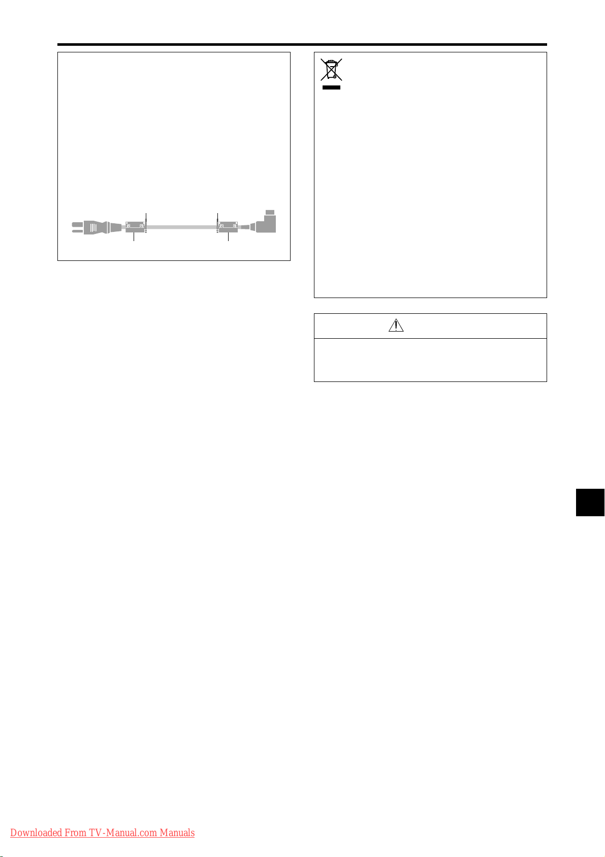
NOTE:
dnd
When you connect a computer to this monitor, use an RGB
cable including the ferrite core on both ends of the cable.
And regarding power cable, attach the supplied ferrite
cores. If you do not do this, this monitor will not conform
to mandatory CE or C-Tick standards.
Set the ferrite cores on both ends of the power cable
(supplied).
Use the band to fasten the ferrite core (supplied) to the
power cable.
wer
supplie
n
Disposing of your used
product
EU-wide legislation as implemented in each
Member State requires that used electrical and
electronic products carrying the mark (left) must
be disposed of separately from normal household
waste. This includes plasma monitors and their
electrical accessories. When you dispose of such
products, please follow the guidance of your local
authority and/or ask the shop where you purchased
the product.
After collecting the used products, they are reused
and recycled in a proper way. This effort will help
us reduce the wastes as well as the negative impact
to the human health and the environment at the
minimum level.
The mark on the electrical and electronic products
only applies to the current European Union Member
States.
CAUTION
When disposing of used batteries, please comply with
governmental regulations or environmental public
instruction’s rules that apply in your country/area.
Downloaded From TV-Manual.com Manuals
En-3

Contents
Important Information .................................. En-2
Contents ...................................................... En-4
Contents of the Package ........................................ En-4
Options .............................................................. En-4
Installation .................................................. En-5
Ventilation Requirements for enclosure mounting ...... En-5
Creating a video wall ........................................... En-6
Cable Management..............................................En-6
Caution when placing the plasma monitor in portrait mode .....
Using the remote control ....................................... En-7
Battery Installation and Replacement ..................... En-7
Using the wired remote control mode .................... En-7
Operating Range .................................................... En-7
Handling the remote control................................... En-7
Part Names and Function .............................. En-8
Front View .......................................................... En-8
Rear View/ Terminal Board ...................................En-9
Remote Control .................................................. En-11
Basic Operations ......................................... En-12
POWER ............................................................ En-12
To turn the unit ON and OFF: .............................. En-12
VOLUME .......................................................... En-12
To adjust the sound volume:................................. En-12
MUTE ............................................................... En-12
To mute the audio: ............................................... En-12
DISPLAY ............................................................En-12
To check the settings:........................................... En-12
DIGITAL ZOOM ................................................. En-12
AUTO ADJUST .................................................. En-12
To adjust the size or quality of the picture automatically:..
OFF TIMER ........................................................En-12
To set the of f timer:.............................................. En-12
To check the remaining time: ............................... En-12
To cancel the off timer: ........................................ En-12
WIDE Operations ......................................... En-13
Wide Screen Operation (manual) ........................ En-13
When viewing videos or digital video discs ......... En-13
Wide Screen Operation with Computer Signals ..... En-14
When “PICTURE SIZE” is set to “OFF” ............. En-14
SPLIT SCREEN Operations ............................. En-15
Showing a couple of pictures on the screen at the same
time .............................................................. En-15
Operations in the Side-by-side mode.................... En-15
Operations in the Picture-in-picture mode ............ En-16
Selecting the input signals to be displayed ........... En-16
Zooming in on a specific input ............................. En-16
Adjusting the OSM controls................................. En-16
OSM(On Screen Menu) Controls .................... En-17
Menu Operations ............................................... En-17
Menu Tree ......................................................... En-18
Picture Settings Menu.......................................... En-20
Adjusting the picture............................................ En-20
Setting the picture mode according to the brightness
of the room ........................................................ En-20
Reducing noise in the picture ............................... En-20
Setting the color temperature ............................... En-20
Adjusting the color to the desired level ................ En-21
Changing the Gamma Curve ................................ En-21
Making the Low T one adjustments ...................... En-21
Adjusting the colors ............................................. En-21
Audio Settings Menu .......................................... En-22
Adjusting the treble, bass and left/right balance and
audio input select............................................... En-22
Setting the allocation of the audio connectors ...... En-22
Image Adjust Settings Menu ................................ En-22
Adjusting the Position, Size, Fine Picture, Picture Adj ....
Option1 Settings Menu ....................................... En-23
Setting the on-screen menu .................................. En-23
Setting the BNC input connector type .................. En-23
Setting the RGB1 connector................................. En-23
Downloaded From TV-Manual.com Manuals
En-7
En-12
En-22
Setting a computer image to the correct RGB select
screen ................................................................ En-23
Setting high definition images to the suitable screen size ..
Setting the Input Skip........................................... En-24
Resetting to the default values.............................. En-24
Option2 Settings Menu ....................................... En-25
Setting the power management for computer images ......
POWER/ST ANDBY indicator ............................. En-25
Setting the picture to suit the movie ..................... En-25
Reducing image retention .................................... En-25
Setting the gray level for the sides of the screen ... En-27
Setting the screen size for S1/S2 video input........ En-27
Setting the picture size for RGB input signals ...... En-28
Setting the signal and black level for DVI signal.. En-28
Option3 Settings Menu ....................................... En-28
Using the timer .................................................... En-28
Setting the power on mode................................... En-30
Enabling/disabling the front panel controls .......... En-30
Enabling/disabling remote control wireless
transmission ...................................................... En-30
Loop Out setting .................................................. En-30
Remote ID setting ................................................ En-30
ID number setting ................................................ En-31
Video Wall setting ................................................ En-31
Option4 Settings Menu ....................................... En-34
Removing the sub screen area when there is no input
signal detected for the sub picture...................... En-34
Displaying the entire image during DIGIT AL ZOOM
operations .......................................................... En-34
Displaying still images in the sub screen .............. En-34
Switching the input source quickly ...................... En-35
Displaying the information as a text ..................... En-35
Advanced OSM Settings Menu ............................ En-36
Setting the menu mode ........................................ En-36
Language Settings Menu ..................................... En-36
Setting the language for the menus....................... En-36
Color System Settings Menu ................................ En-36
Setting the video signal format............................. En-36
Source Information Menu ....................................En-36
Checking the frequencies, polarities of input signals,
and resolution .................................................... En-36
External Control ......................................... En-37
Application ....................................................... En-37
Connections ...................................................... En-37
Type of connector: D-Sub 9-pin male .................. En-37
Communication Parameters ................................. En-37
External Control Codes (Reference) ...................... En-37
Pin Assignments ......................................... En-37
mini D-Sub 15-pin connector (Analog) ................. En-37
DVI-D 24-pin connector (Digital) ..........................En-37
Troubleshooting .......................................... En-38
Table of Signals Supported .......................... En-39
Specifications ............................................. En-43
Contents of the Package
䡺 Plasma monitor
䡺 Power cord
䡺 Remote control with two AAA Batteries
䡺 Manuals (Start up Guide and CD-ROM)
䡺 Ferrite cores
䡺 Cable clamps
Options
• Wall mount unit
• Ceiling mount unit
• Tilt mount unit
• T abletop Stand
• Attachable speakers
En-4
En-24
En-25
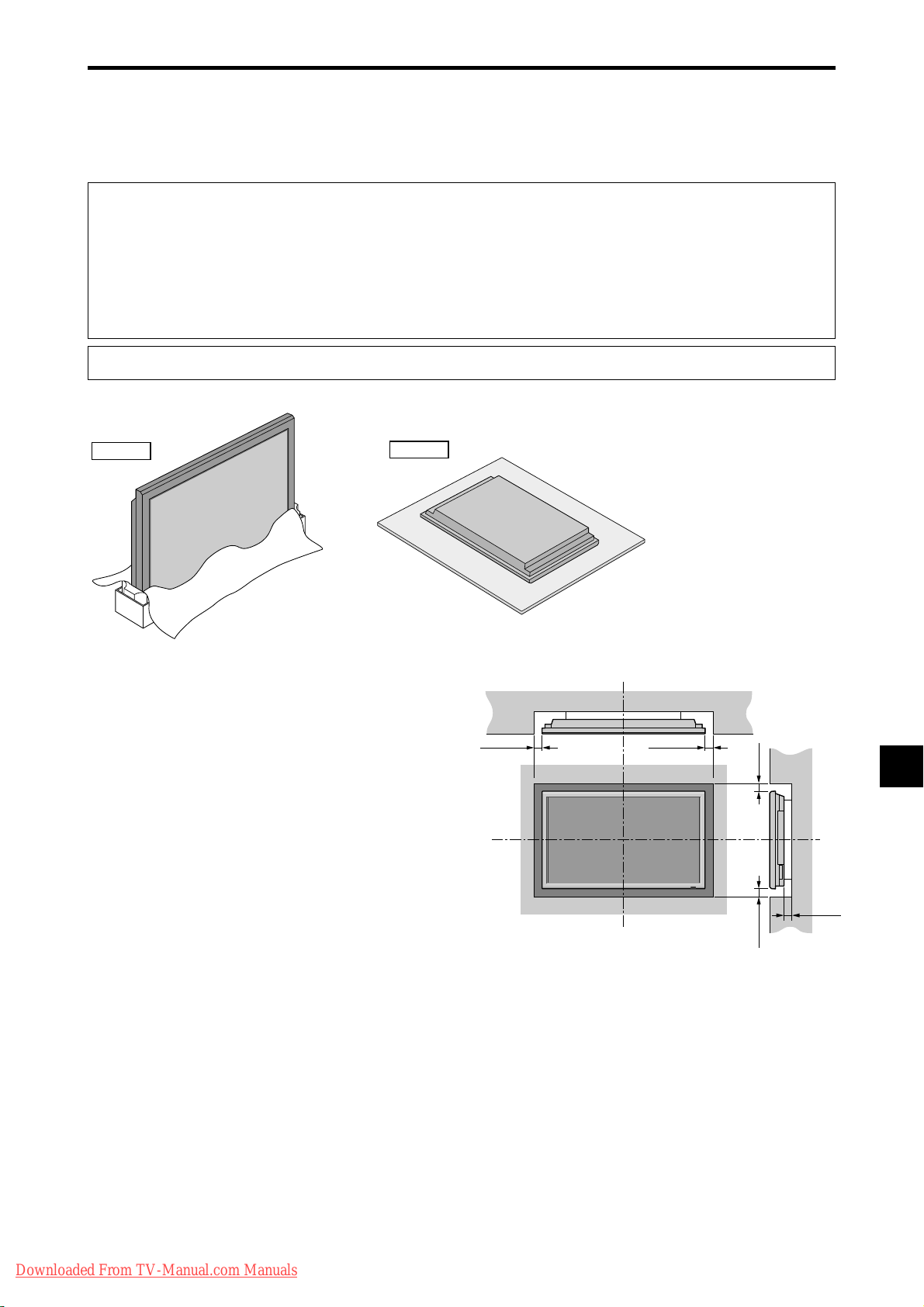
50mm (2")
50
mm
(2") 50
mm
(2")
Wall
Wall
50mm (2")
50mm (2")
Installation
You can attach your optional mounts or stand to the plasma monitor in one of the following two ways:
* While it is upright. (See Drawing A)
* As it is laid down with the screen face down (See Drawing B). Lay the protective sheet, which was wrapped around the
monitor when it was packaged, beneath the screen surface so as not to scratch the screen face.
* Do not touch or hold the screen face when carrying the unit.
• This device cannot be installed on its own. Be sure to use a stand or original mounting unit. (Wall
mount unit, Stand, etc.)
• For correct installation and mounting it is strongly recommended to use a trained, authorized
dealer.
Failure to follow correct mounting procedures could result in damage to the equipment or injury
to the installer.
Product warranty does not cover damage caused by improper installation.
* Use only a mounting kit or stand recommended by the manufacturer and listed as an accessory.
Drawing A
Drawing B
Ventilation Requirements for
enclosure mounting
T o allow heat to disperse, leave space between surrounding
objects as shown on the diagram when installing.
Downloaded From TV-Manual.com Manuals
En-5
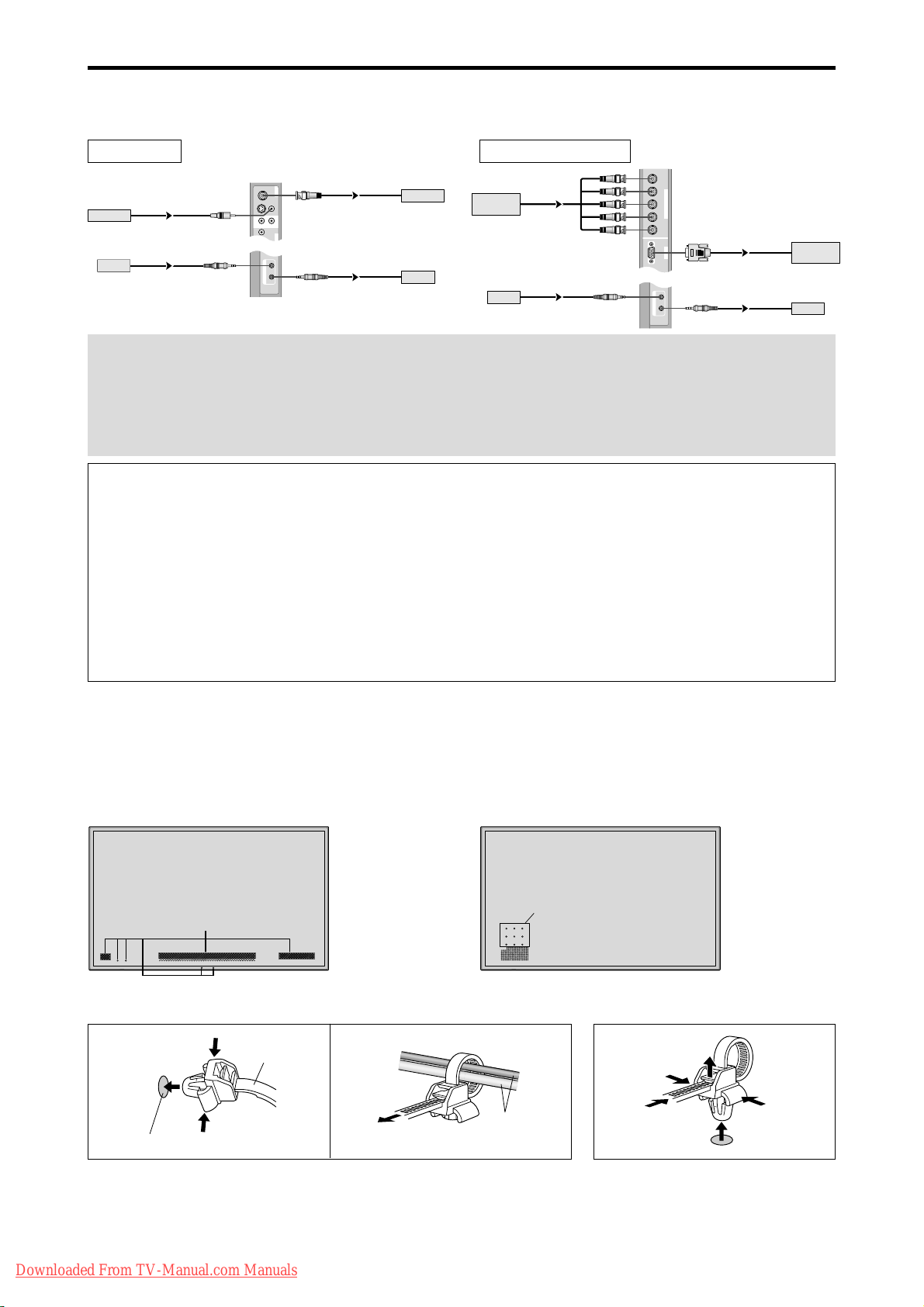
Creating a video wall
RGB
2
/
DVD
2
/
HD
2
RGB
1
R/
VD
G/ B/
HD
(
IN/OUT
)
Cr/Pr Y Cb/Pb
IN OUT
REMOTE
BNC connector
RGB signal/
DVD/HD signal
IN
OUT
IN
OUT
Remote
control
RGB signal/
DVD/HD signal
Remote
control
With built-in matrix display capability, you can create a (2⳯2, 3⳯3, 4⳯4, 5⳯5) video wall.
• Connect signal cables and remote cables as shown below.
Video signal RGB/DVD/HD signal
VIDEO
BNC connector
VIDEO
(
IN/OUT
1
)
VIDEO
VIDEO
2
VIDEO Signal
Remote
control
RCA phono plug
IN
IN
3
AUDIO
(
MONO
)
R
L
1
Y
DVD
1
IN OUT
REMOTE
Note:
1. The VIDEO1 and RGB1 terminals can be used for either INPUT or OUTPUT.
When LOOP OUT is ON, do not connect an OUTPUT signal fr om another unit as it may damage the other unit due
to an extraordinary load.
2. LOOP OUT can not be turned ON while signals are input to the RGB1 terminal.
3. LOOP OUT can be turned ON while signals are input to the RGB1 terminal if the POWER is switched ON.
Information
• T o loop signals out to another plasma display, set the LOOP OUT to ON.
• To create a video wall, set the VIDEO WALL menu items properly.
• To connect monitors, please use a 1~2m (3.3~6.6 feet) BNC cable (any commercially available cable).
• If the image quality is poor, do not use the monitor’s out terminal. Use a distribution amplifier (any commercially
available distribution amplifier) to connect the split signals to the respective monitor INPUT terminals.
• Being used as a video wall function, maximaly 4-screen is rough-standard with lower than 1024⳯768, 60Hz
signal.
• A distribution amplifier is particularly recommended when creating a 3⳯3 (or greater) video wall.
• When looping from plasma to plasma, a 1~2m (3.3~6.6 feet) 15 pin male D-Sub - 5BNC conversion cable is
required.
OUT
OUT
VIDEO Signal
Remote
control
Cable Management
Using the cable clamps provided with the plasma display; Bundle the signal and audio cables at the back of the unit to
connect to the display.
42 inch 50/61 inch
Back of the unit
mounting holes
To attach To detach
1. 2.
clamp
cables
mounting hole
Back of the unit
mounting holes
Downloaded From TV-Manual.com Manuals
En-6
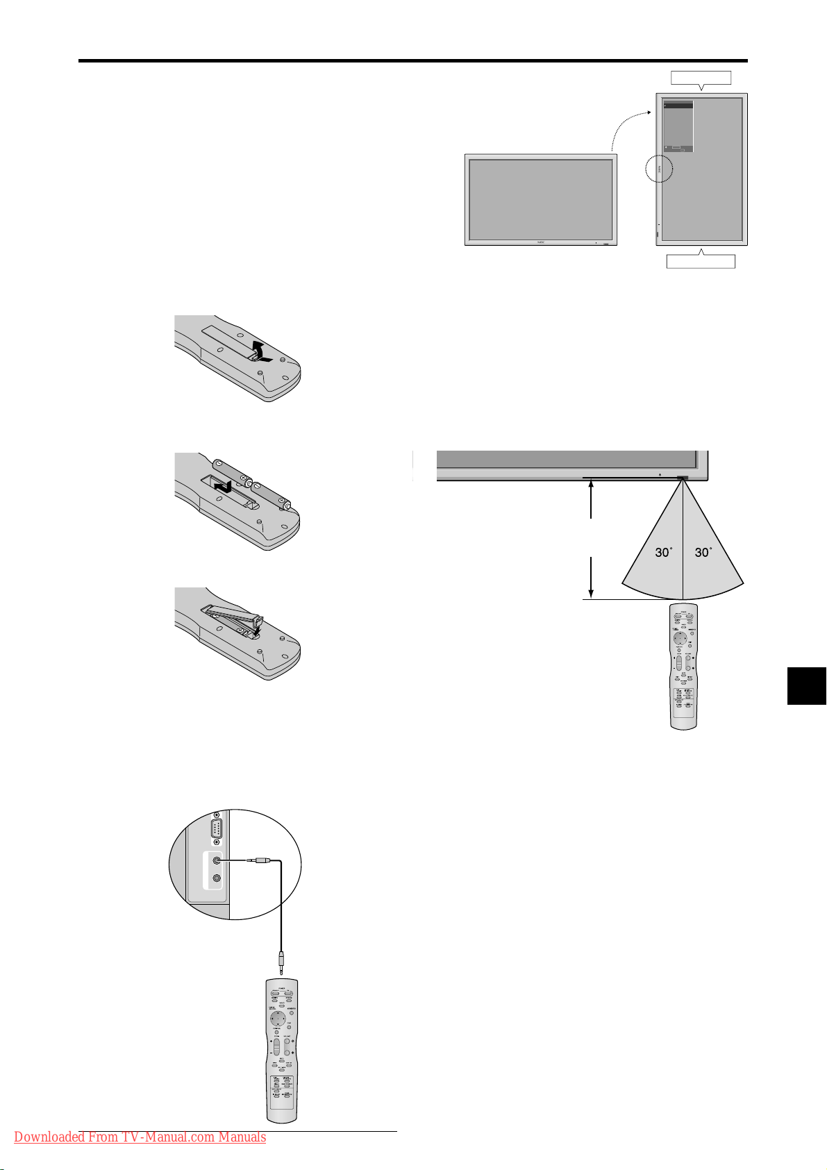
Caution when placing the plasma monitor in portrait mode
External Control
IN OUT
REMOTE
• Use the optional unit. Contact your store of purchase when installing.
• Rotate 90° clockwise as seen from the front when installing.
• After installing, make sure the NEC logo is located at the
left hand side of the screen when facing the plasma from
the front.
• Be sure to set “OSM ANGLE” to “V” when using.
* Failure to heed the above cautions may lead to malfunction.
90°
Top side
OPTION1
MENU/ENTER
OSM
DOWN UP LEFT/
VOLUME
BNC INPUT
: RGB
-
RIGHT/
D-SUB INPUT
+
INPUT SELECT
/EXIT
: RGB
RGB SELECT
: AUTO
HD SELECT
: 1080B
INPUT SKIP
: OFF
ALL RESET
: OFF
1024ⴒ768
SEL.
MENU/ENTER
OK
EXIT
RETURN
Using the remote control
Battery Installation and Replacement
Insert the 2 “AAA” batteries, making sure to set them in
with the proper polarity.
1.Press and open the cover.
2.Align the batteries according to the (+) and (–) indication
inside the case.
3.Replace the cover.
INPUT SELECT
VOLUME
MENU/ENTER
DOWN UP LEFT/-RIGHT/+/EXIT
Bottom side
Operating Range
* Use the remote control within a distance of about 7 m/
23ft. from the front of the monitor’s remote control sensor
and at horizontal and vertical angles of up to approximately
30°.
* The remote control operation may not function if the
monitor’s remote control sensor is exposed to direct
sunlight or strong artificial light, or if there is an obstacle
between the sensor and the remote control.
Approx.
7m/23ft
Using the wired remote control mode
Connect the remote cable* to the remote control’s remote
jack and the “REMOTE IN” terminal on the monitor.
When the cable is connected, the mode automatically
switches to wired remote control. When the wired remote
control mode is used, the remote control can be operated
even if no batteries are loaded.
Remote Control
Cable*
To Remote Jack
Handling the remote control
• Do not drop or mishandle the remote control.
• Do not get the remote control wet. If the remote control
gets wet, wipe it dry immediately.
• Avoid heat and humidity.
• When not using the remote control for a long period,
remove the batteries.
• Do not use new and old batteries together, or use different
types together.
• Do not take apart the batteries, heat them, or throw them
into a fire.
• When using the remote control in the wireless condition,
be sure to unplug the remote cable from the REMOTE
IN terminal on the monitor.
Downloaded From TV-Manual.com Manuals
* The 1/8 Stereo Mini cable must be purchased separately.
En-7
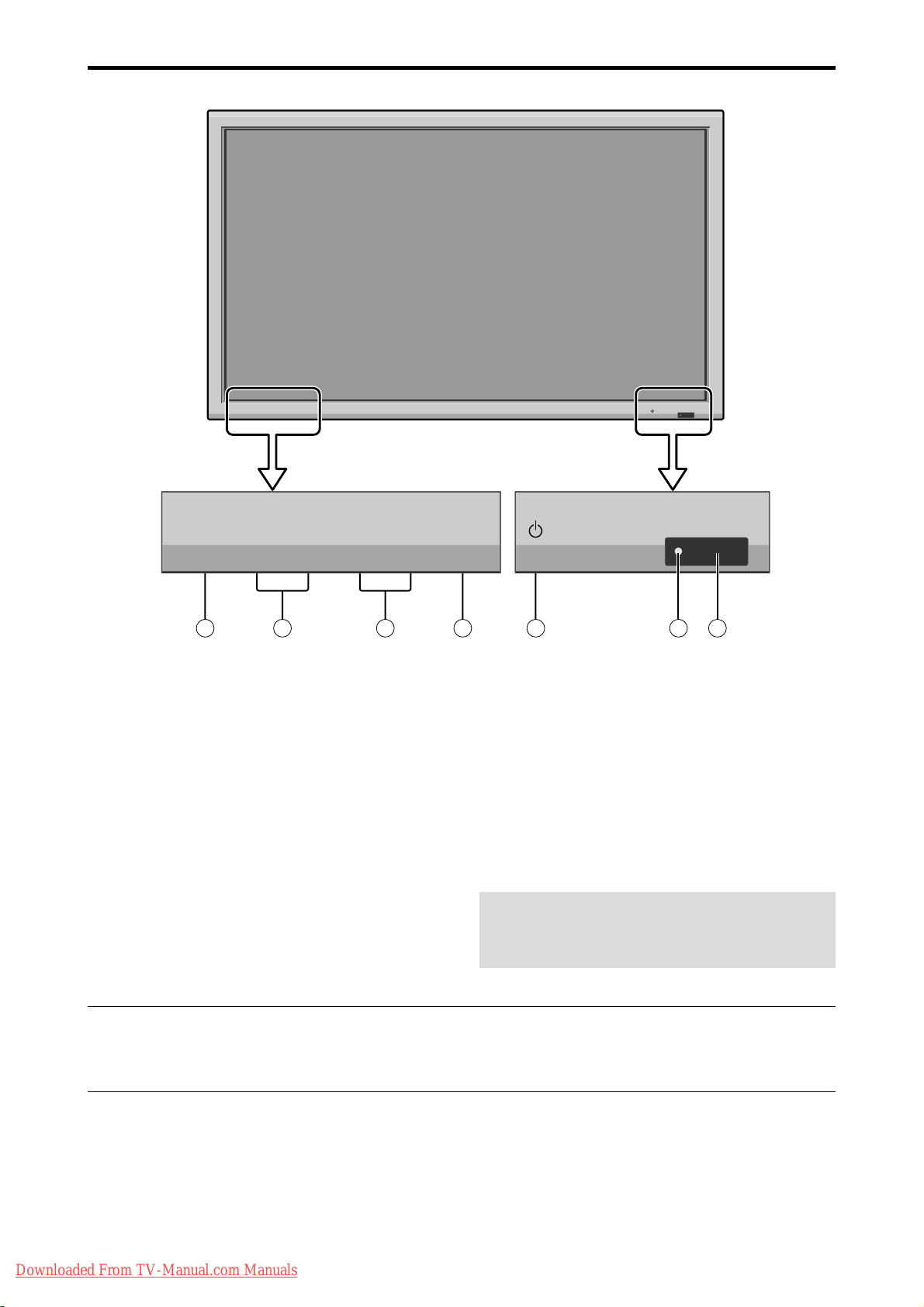
Part Names and Function
Front View
INPUT SELECT
VOLUME
MENU/ENTER
DOWN UP LEFT/-RIGHT/+/EXIT
MENU/ENTER
7
VOLUME
DOWN UP LEFT/-RIGHT/
6
5
q Power
Turns the monitor’s power on and off.
w Remote sensor window
Receives the signals from the remote control.
e POWER/STANDBY indicator
When the power is on ............................. Lights green.
When the power is in the standby mode ... Lights red.
r INPUT SELECT / EXIT
Switches the input.
Functions as the EXIT buttons in the On-Screen Menu
(OSM) mode.
INPUT SELECT
+
/EXIT
4
1
2
3
t LEFT/– and RIGHT/+
Enlarges or reduces the image. Functions as the
CURSOR (
/ ) buttons in the On-Screen Menu
(OSM) mode.
y VOLUME DOWN and UP
Adjusts the volume. Functions as the CURSOR (▲/
▼) buttons in the On-Screen Menu (OSM) mode.
u MENU/ENTER
Sets the On-Screen Menu (OSM) mode and displays
the main menu.
WARNING
The Power on/off switch does not completely
disconnect power from the display.
Note:
This plasma monitor has the capasity to display images when connected to European DVD players with a SCART
output signal, which is RGB with composite sync.
Your dealer can supply a special SCART cable, which will enable you to use the RGB with composite sync signal.
To obtain the special cable as well as for further information, please contact your dealer.
Downloaded From TV-Manual.com Manuals
En-8
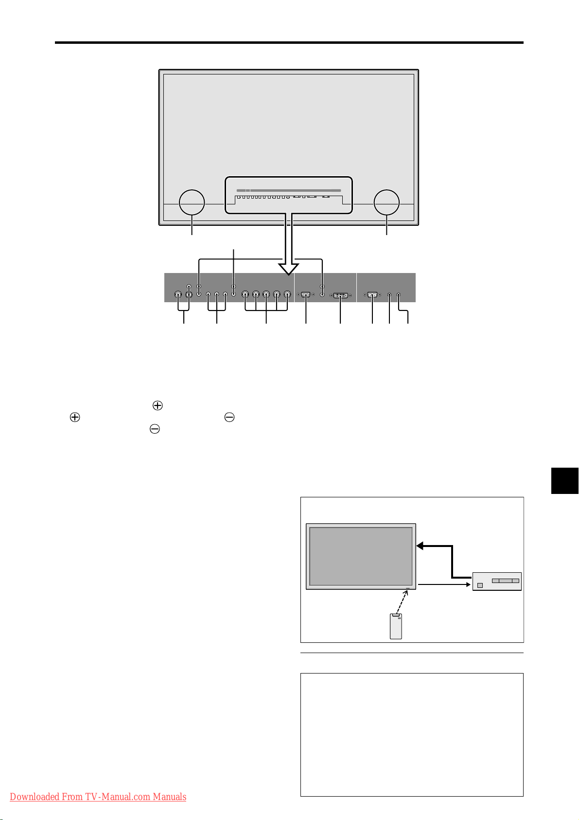
Rear View/ Terminal Board
42 inch
BD A
(IN/OUT)
R
Y Cb/Pb Cr/Pr
3
L
(
)
MONO
1
DVD
1
/
HD
1
AUDIO
1
VIDEO
2
CE F GHIJK
AUDIO
2
R
(
)
MONO
L
VIDEO
DVD
1
/
HD
1
AUDIO
1
YL/R L/RCb/Pb Cr/Pr
RGB
R/Cr/Pr G/Y B/C b/Pb
RGB
2
/
DVD
2
/
HD2RGB
2
AUDIO
R/Cr/Pr G /Y B/Cb/Pb
2
/
DVD
1
AUDIO
3
RGB 3EXTERNAL CONTROL
(IN/OUT)
VD L/RHD
2
/
HD
2
RGB
VDHD
(IN/OUT)
REMOTE
IN OUT
DVI
1
AUDIO
3
RGB
3
R
(
)
Digital RGB
DVI
(
)
L
MONO
EXTERNAL CONTROL
REMOTE
IN OUT
A AC IN
Connect the included power cord here.
B EXT SPEAKER L and R
Connect speakers (optional) here. Maintain the correct
polarity. Connect the (positive) speaker wire to the
EXT SPEAKER terminal and the (negative)
speaker wire to the
EXT SPEAKER terminal on
both LEFT and RIGHT channels.
Please refer to your speaker’s owner’s manual.
C VIDEO1, 2, 3 (BNC, RCA, S-Video)
Connect VCR’s, DVD’s or Video Cameras, etc. here.
VIDEO1 can be used for Input or Output.
D AUDIO1, AUDIO2, AUDIO3
These are audio input terminals.
The input is selectable. Set which video image corresponds
to the audio input from the audio menu screen.
E DVD1 / HD1
Connect DVD’s, High Definition or Laser Discs, etc.
here.
F RGB2/ DVD2/ HD2
RGB2: Y ou can connect an analog RGB signal
and the syncronization signal.
DVD2/ HD2: You can connect DVDs, High
Definition sources, Laser Discs, etc.
here.
This input can be set for use with an
RGB or component source.
G RGB1 (mini D-Sub 15pin)
Connect an analog RGB signal from a computer, etc.
here. This input can be used for Input or Output.
H RGB3 (DVI 24pin)
Connect a digital signal (TMDS) from a source with a
DVI output.
Downloaded From TV-Manual.com Manuals
This input can be set for use with an RGB/PC3.
I EXTERNAL CONTROL
This terminal is used when operating and controlling
the monitor externally with a control system (by RS232C).
J REMOTE IN (DC +5V)
Connect the remote cable* to the remote control’s
remote jack to obtain wired remote control.
K REMOTE OUT (C-MOS DC +5V)
Connect the remote cable* to the REMOTE IN jack of
the other display monitor to obtain wired remote
control.
Connection Example: Connecting a TV tuner
PLASMA DISPLAY
VIDEO
IN
VIDEO
OUT
REMOTE
OUT
REMOTE
IN
TV T uner
Remote Control
Carrier fHz: 38kHz
* The 1/8 Stereo Mini cable must be purchased separately.
Information
• For Y/CB/Cr, connect to the DVD1 or DVD2
terminals.
• For SCART , this unit provides three ways to connect:
· SCART1: Connect R/G/B to the DVD2 terminals
and composite sync. to the HD terminal.
· SCART2: Connect R/G/B to the DVD2 terminals
and composite sync. to the VIDEO1 terminal.
· SCART3: Connect R/G/B + composite sync. to the
RGB1 terminal.
En-9
TV T uner
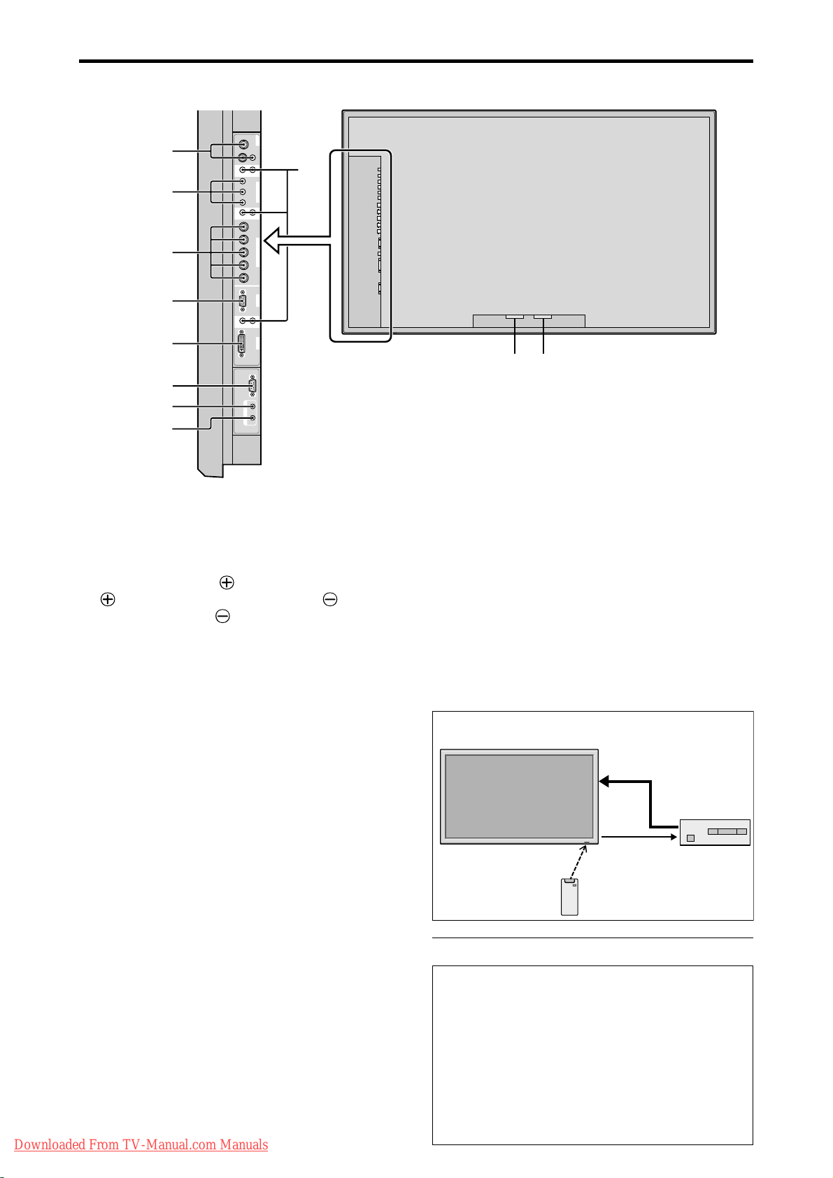
Rear View/ Terminal Board
51/61 inch
VIDEO
VIDEO
1
C
E
F
G
H
I
J
K
VIDEO 2VIDEO
3
AUDIO
(
MONO
)
R
L
(
MONO
)
(
MONO
)
L
L
External Control
REMOTE
Y Cb/Pb Cr /Pr
DVI
(
Digital RGB
)
IN OUT
1
DVD
1
/
HD
1
AUDIO
R
2
Cr/Pr Y Cb/Pb
R/
G/ B/
RGB
2
/
DVD
2
/
HD
2
HD
VD
RGB
1
AUDIO
R
3
RGB
3
D
A
B
A AC IN
Connect the included power cord here.
B EXT SPEAKER L and R
Connect speakers (optional) here. Maintain the correct
polarity. Connect the (positive) speaker wire to the
EXT SPEAKER terminal and the (negative)
speaker wire to the
EXT SPEAKER terminal on
both LEFT and RIGHT channels.
Please refer to your speaker’s owner’s manual.
C VIDEO1, 2, 3 (BNC, RCA, S-Video)
Connect VCR’s, DVD’s or Video Cameras, etc. here.
VIDEO1 can be used for Input or Output.
D AUDIO1, AUDIO2, AUDIO3
These are audio input terminals.
The input is selectable. Set which video image corresponds
to the audio input from the audio menu screen.
E DVD1 / HD1
Connect DVD’s, High Definition or Laser Discs, etc.
here.
F RGB2/ DVD2/ HD2
RGB2: Y ou can connect an analog RGB signal
and the syncronization signal.
DVD2/ HD2: You can connect DVDs, High
Definition sources, Laser Discs, etc.
here.
This input can be set for use with an
RGB or component source.
G RGB1 (mini D-Sub 15pin)
Connect an analog RGB signal from a computer, etc.
here. This input can be used for Input or Output.
H RGB3 (DVI 24pin)
Connect a digital signal (TMDS) from a source with a
DVI output.
Downloaded From TV-Manual.com Manuals
This input can be set for use with an RGB/PC3.
I EXTERNAL CONTROL
This terminal is used when operating and controlling
the monitor externally with a control system (by RS232C).
J REMOTE IN (DC +5V)
Connect the remote cable* to the remote control’s
remote jack to obtain wired remote control.
K REMOTE OUT (C-MOS DC +5V)
Connect the remote cable* to the REMOTE IN jack of
the other display monitor to obtain wired remote
control.
Connection Example: Connecting a TV tuner
PLASMA DISPLAY
VIDEO
IN
VIDEO
OUT
REMOTE
OUT
REMOTE
IN
TV T uner
Remote Control
Carrier fHz: 38kHz
* The 1/8 Stereo Mini cable must be purchased separately.
Information
• For Y/CB/Cr, connect to the DVD1 or DVD2
terminals.
• For SCART , this unit provides three ways to connect:
· SCART1: Connect R/G/B to the DVD2 terminals
and composite sync. to the HD terminal.
· SCART2: Connect R/G/B to the DVD2 terminals
and composite sync. to the VIDEO1 terminal.
· SCART3: Connect R/G/B + composite sync. to the
RGB1 terminal.
En-10
TV T uner
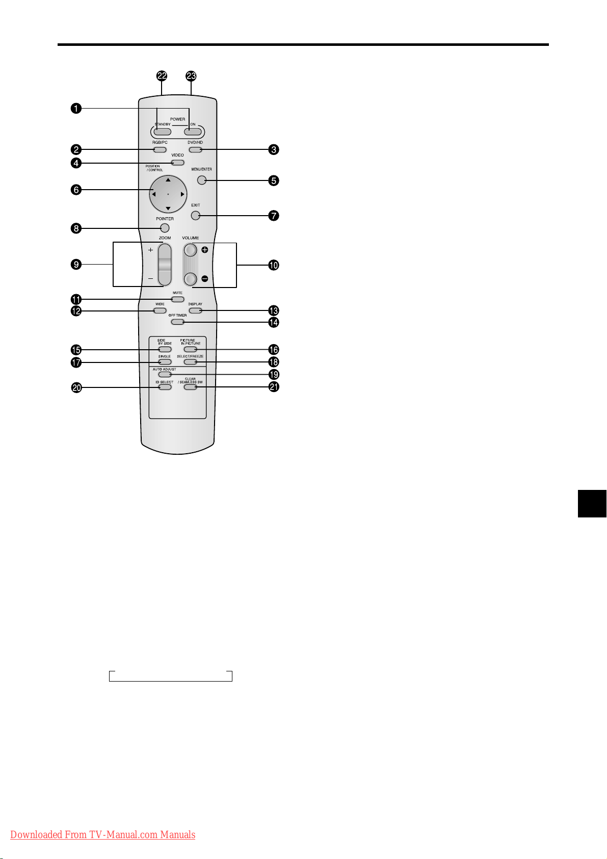
Remote Control
q POWER ON/STANDBY
Switches the power on/standby.
(This does not operate when the POWER/ST ANDBY
indicator of the plasma is off.)
w RGB/PC
Press this button to select RGB/PC as the source.
RGB/PC can also be selected using the INPUT
SELECT button on the monitor.
e DVD / HD
Press this button to select DVD/HD as the source.
DVD/HD can also be selected using the INPUT
SELECT button on the monitor.
r VIDEO
Press this button to select VIDEO as the source.
→ VIDEO1 → VIDEO2 → VIDEO3
VIDEO can also be selected using the INPUT SELECT
button on the monitor.
t MENU/ENTER
Press this button to access the OSM controls.
Press this button during the display of the main menu
to go to the sub menu.
y CURSOR (▲ / ▼ /
Use these buttons to select items or settings and to
adjust settings or switch the display patterns.
/ )
u EXIT
Press this button to exit the OSM controls in the main
menu. Press this button during the display of the sub
menu to return to the previous menu.
i POINTER
Press this button to display the pointer.
o ZOOM (+ /–)
Enlarges or reduces the image.
!0 VOLUME (+ /–)
Adjusts the audio volume.
!1 MUTE
Mutes the audio.
!2 WIDE
Automatically detects the signal and sets the aspect ratio.
Wide button is not active for all signals.
!3 DISPLAY
Displays the source settings on the screen.
!4 OFF TIMER
Activates the off timer for the unit.
!5 SIDE BY SIDE
Press this button to show a couple of pictures in the
side-by-side mode.
!6 PICTURE IN PICTURE
Press this button to show a couple of pictures in the
picture-in-picture mode.
!7 SINGLE
Cancels the split screen mode.
!8 SELECT/FREEZE
Press this button to select the active picture in a split
screen mode.
When the PIC FREEZE function is operating, this
button can be used to display still images on the sub
screen.
!9 AUTO ADJUST
Press this button to adjust Fine Picture, Picture ADJ,
Position, and Contrast automatically. Press the button
in video mode and the Auto Adjust switches to ZOOM
mode automatically when a letter box image is
displayed.
@0 ID SELECT
Set the ID number in the remote control. The remote
control can then be used only for a display with the
same ID number. When several displays are used
together they can be controlled individually.
@1 CLEAR/SEAMLESS SW
Clears the number set by the ID SELECT button.
When the SEAMLESS SW function is operating, this
button can be used to switch the input source quickly.
@2 Remote control signal transmitter
Transmits the remote control signals.
@3 Remote Jack
Insert the plug of the remote cable (The 1/8 Stereo
Mini cable) here when using the supplied remote
control in the wired condition.
Downloaded From TV-Manual.com Manuals
En-11
Basic Operations
POWER
To turn the unit ON and OFF:
1. Plug the power cord into an active AC power outlet.
2. Press the Power button (on the unit).
The monitor’s POWER/STANDBY indicator turns red
and the standby mode is set.
3. Press the POWER ON button (on the remote control) to
turn on the unit.
The monitor’s POWER/STANDBY indicator will light
up (green) when the unit is on.
Press the POWER ST ANDBY button (on the remote control)
4.
or the Power button (on the unit) to turn off the unit.
The monitor’s POWER/STANDBY indicator turns red
and the standby mode is set (only when turning off the
unit with the remote control).
VOLUME
To adjust the sound volume:
1. Press and hold the VOLUME button (on the remote
control or the unit) to increase to the desired level.
2. Press and hold the VOLUME
control or the unit) to decrease to the desired level.
button (on the remote
MUTE
To mute the audio:
Press the MUTE button on the remote control to mute the
audio; press again to restore.
DISPLAY
To check the settings:
1. The screen changes each time the DISPLAY button is
pressed.
2. If the button is not pressed for approximately three seconds,
the menu turns off.
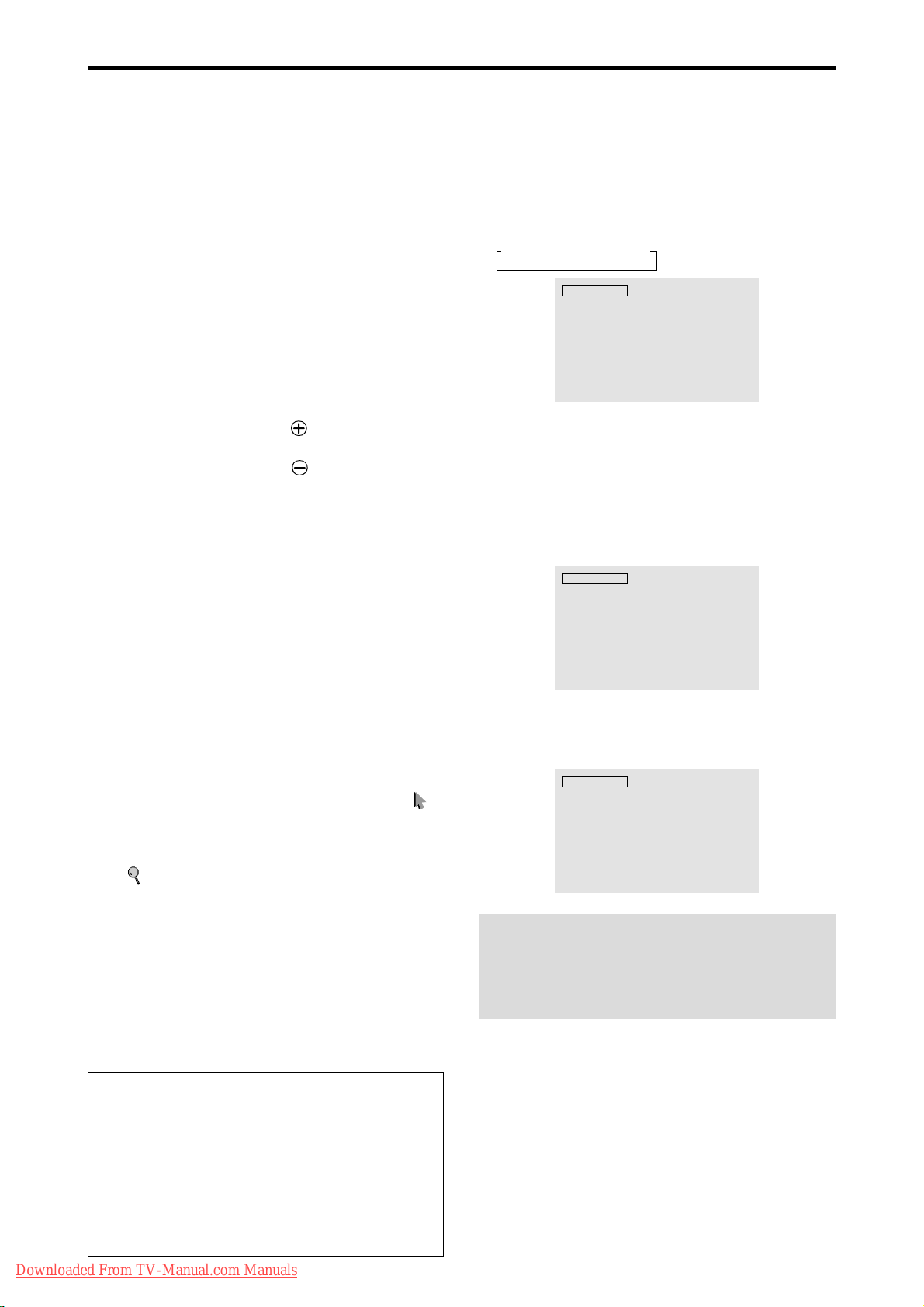
DIGITAL ZOOM
Digital zoom specifies the picture position and enlarges
the picture.
1. (Be sure ZOOM NAV is off.)
Press the POINTER button to display the pointer. ( )
To change the size of the picture:
Press the ZOOM+ button and enlarge the picture.
The pointer will change to resemble a magnifying glass.
)
(
A press of the ZOOM- button will reduce the picture
and return it to its original size.
To change the picture position:
Select the position with the ▲▼
2. Press the POINTER button to delete the pointer.
buttons.
AUTO ADJUST
To adjust the size or quality of the picture
automatically:
Press the AUT O ADJUST button.
OFF TIMER
To set the off timer:
The off timer can be set to turn the power off after 30, 60,
90 or 120 minutes.
1. Press the OFF TIMER button to start the timer at 30
minutes.
2. Press the OFF TIMER button to the desired time.
3. The timer starts when the menu turns off.
→ 30 → 60 → 90 → 120 → 0
OFF TIMER 30
To check the remaining time:
1. Once the off timer has been set, press the OFF TIMER
button once.
2. The remaining time is displayed, then turns off after a few
seconds.
3. When five minutes remain the remaining time appears
until it reaches zero.
OFF TIMER 28
To cancel the off timer:
1. Press the OFF TIMER button twice in a row.
2. The off timer is canceled.
OFF TIMER 0
Note:
After the power is turned off with the off timer ...
A slight current is still supplied to the monitor. When you
are leaving the r oom or do not plan to use the system for a
long period of time, turn off the power to the monitor.
Information
AUTO ADJUST ON setting
When RGB (still picture) input is selected:
Fine Picture, Picture ADJ, Position, and Contrast will
be adjusted automatically.
When RGB (motion picture), VIDEO, or Y/Pb/Pr
(component) input is selected:
The screen size switches to ZOOM mode automatically
when a letter box image is displayed.
Downloaded From TV-Manual.com Manuals
En-12
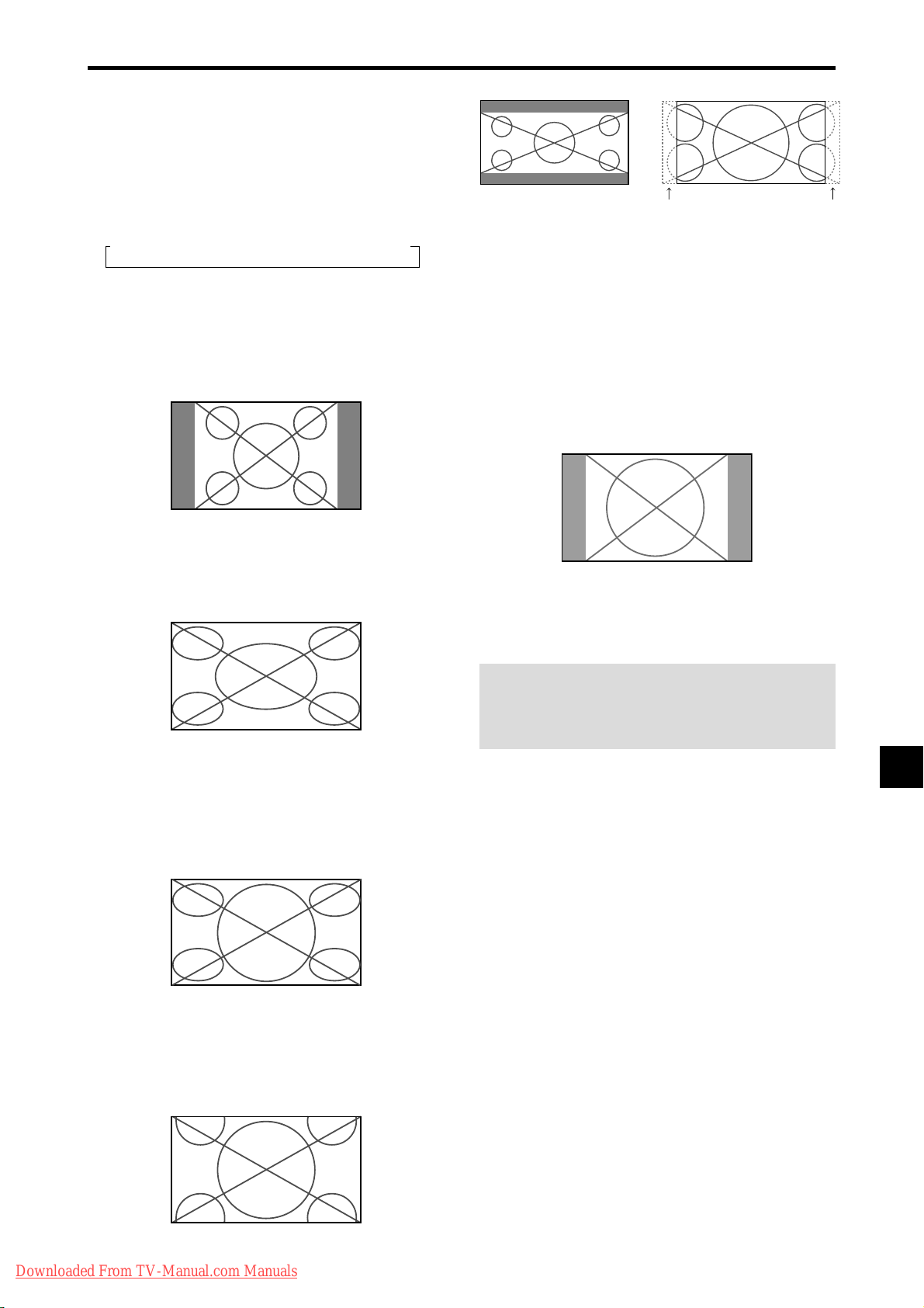
WIDE Operations
Wide Screen Operation
With this function, you can select one of six screen sizes.
(manual)
When viewing videos or digital video discs
1. Press the WIDE button on the remote control.
2. Within 3 seconds ...
Press the WIDE button again.
The screen size switches as follows:
→ NORMAL → FULL → STADIUM → ZOOM → 2.35:1 → 14:9
When a 720P or 1080I signal is input:
FULL ↔ 2.35:1
When displaying enhanced split screen:
NORMAL ↔ FULL
NORMAL size screen (4:3)
The normal size screen is displayed.
* The picture has the same size as video pictures with a 4 : 3
aspect ratio.
FULL size screen
2.35:1 size screen
Original image
Information is lost on both sides.
The squeezed film image is expanded to fulfill the entire
screen at a ratio of 2.35:1. Black bands do not appear at
the top and bottom but information is lost on the left and
right margins.
• This feature is available when the input signal is video,
component (480I, 480P, 576I, 576P, 720P, 1080I) or RGB
(525P or 625P signal from a scan converter).
* If black bands appear on the top and bottom in the full size
screen, select the 2.35:1 size screen to fill the screen and
avoid image retention.
14:9 size screen
The image is displayed at a 14:9 aspect ratio.
* This feature is available when the input signal is video,
component (480I, 480P , 576I, 576P) or RGB (525P or 625P
signal from a scan converter).
The image is expanded in the horizontal direction.
* Images compressed in the horizontal direction (“squeezed
images”) are expanded in the horizontal direction and
displayed on the entire screen with correct linearity.
(Normal images are expanded in the horizontal direction.)
STADIUM size screen
The picture is expanded in the horizontal and vertical
directions at different ratios.
* Use this for watching normal video programs (4:3) with a
wide screen.
ZOOM size screen
Note:
Do not allow 4:3 content to be displayed for extended
periods of time without using gray bars. This can cause
image retention.
The picture is expanded in the horizontal and vertical
Downloaded From TV-Manual.com Manuals
direction, maintaining the original proportions.
* Use this for theater size (wide) movies, etc.
En-13
 Loading...