

MultiSync™ SC40
MultiSync™ SC46


English
Français
Español
EnglishFrançaisEspañol


Table of Contents
Important Information ...........................................................................................................................English-2
Safety Precautions and Maintenance ...................................................................................................English-3
Recommended Use ....................................................................................................................................English-4
Package Contents .....................................................................................................................................English-5
Installation
Mounting .....................................................................................................................................English-6
Attaching Mounting Accessories ...........................................................................................English-7
Ventilation Requirements, Main Power Switch Cover, Prevent Tipping .........................English-9
Part Names and Functions
Control Panel ..............................................................................................................................English-9
Terminal Panel ............................................................................................................................English-10
Remote Control ..........................................................................................................................English-11
Remote Control Operating Range ..........................................................................................English-13
Remote Control ID Function....................................................................................................English-14
Setup ............................................................................................................................................................English-15
Connections
Connecting the LCD Monitor to a PC .....................................................................................English-17
Connecting to a Macintosh Computer ..................................................................................English-18
Connecting to a Computer with a Digital Output ..............................................................English-19
Connecting a DVD Player with component out ...................................................................English-20
Connecting a DVD Player with HDMI out ..............................................................................English-21
Connecting to a Stereo Amplier ..........................................................................................English-22
Basic Operation
Power On and Off Modes ...........................................................................................................English-23
Power Indicator .........................................................................................................................English-24
Power Management Function .................................................................................................English-24
Picture Size.................................................................................................................................English-24
Picture Mode ..............................................................................................................................English-24
Information OSD ........................................................................................................................English-24
OSD (On-Screen-Display) Controls ..........................................................................................................English-25
Picture .........................................................................................................................................English-26
Adjust ...........................................................................................................................................English-26
Audio ............................................................................................................................................English-27
Schedule ......................................................................................................................................English-27
PIP (Picture-in-Picture) ...........................................................................................................English-28
OSD ................................................................................................................................................English-28
Multi Display ...............................................................................................................................English-29
Display Protection .....................................................................................................................English-29
Advanced Option ........................................................................................................................English-30
TV Tuner .......................................................................................................................................English-31
Digital Tuner Operation ...........................................................................................................English-32
NOTE .............................................................................................................................................English-33
Using the LCD with RS-232C ....................................................................................................................English-34
Features ......................................................................................................................................................English-39
Troubleshooting.........................................................................................................................................English-40
References ..................................................................................................................................................English-41
Specications ............................................................................................................................................English-42
Pin Assignment ..........................................................................................................................................English-44
Limited Warranty ......................................................................................................................................English-45
Manufacturer’s Recycling and Energy Information ..........................................................................English-46

Table des matières
Informations importantes ......................................................................................................................Français-2
Consignes de sécurité et d’entretien ...................................................................................................Français-3
Utilisation recommandée ....................................................................................................................... Français-4
Contenu de la boîte ................................................................................................................................. Français-5
Installation
Montage...................................................................................................................................... Français-6
Fixation des accessoires de montage ...................................................................................Français-7
Exigences de ventilation, Couvercle de l’interrupteur d’alimentation principal,
Éviter le renversement ........................................................................................................... Français-8
Nom des pièces et fonctions
Panneau de commande
Panneau de borne ....................................................................................................................Français-10
Télécommande .........................................................................................................................
Plage de fonctionnement pour la télécommande ............................................................Français-13
ID Télécommande fonctionne ...............................................................................................Français-14
Conguration ........................................................................................................................................... Français-15
Branchements
Brancher le moniteur ACL au PC .......................................................................................... Français-17
Brancher à un ordinateur Macintosh® ...............................................................................Français-18
Brancher à un ordinateur avec sortie numérique ...........................................................Français-19
Branchement d’un lecteur DVD via la sortie de composant .........................................Français-20
Branchement d’un lecteur DVD via la sortie HDMI ..........................................................Français-21
Branchement à un amplicateur stéréophonique .......................................................... Français-22
Fonctionnement de base
Modes SOUS et HORS tension ............................................................................................... Français-23
Voyant d’alimentation ........................................................................................................... Français-24
Gestion de la consommation ................................................................................................ Français-24
Taille de l’image ......................................................................................................................Français-24
Mode image .............................................................................................................................. Français-24
Information OSD ..................................................................................................................... Français-24
Commandes OSD (gestionnaire à l’écran) .......................................................................................... Français-25
Image ........................................................................................................................................Français-26
Régler ........................................................................................................................................ Français-26
Audio ..........................................................................................................................................Français-27
Calendrier ................................................................................................................................Français-28
Image Dans Image (PIP) ......................................................................................................... Français-28
OSD ............................................................................................................................................. Français-28
Afchages Multiples ............................................................................................................... Français-26
Protection Afchage .............................................................................................................. Français-29
Option Avancée ....................................................................................................................... Français-30
Syntoniseur TV ........................................................................................................................ Français-32
Opération de syntonisation numérique .............................................................................Français-33
Remarques ............................................................................................................................... Français-34
Utiliser l’ACL avec RS-232C ................................................................................................................... Français-35
Fonctions..................................................................................................................................................Français-40
Dépannage ................................................................................................................................................Français-41
Références ............................................................................................................................................... Français-42
Caractéristiques .................................................................................................................................... Français-43
Affectation des broches .......................................................................................................................Français-45
Garantie limitée .....................................................................................................................................Français-46
Informations du fabricant relatives au recylage et aux économies d’énergie ........................ Français-47
............................................................................................................ Français-9
Français-11

Índice
Información importante .........................................................................................................................Español-2
Precauciones de seguridad y mantenimiento ....................................................................................Español-3
Uso recomendado ......................................................................................................................................Español-4
Contenidos del paquete ...........................................................................................................................Español-5
Instalación
Montaje ........................................................................................................................................Español-6
Conexión de accesorios de montaje ......................................................................................Español-7
Requisitos de ventilación, Tapa del interruptor de corriente principal,
Prevención de caídas ................................................................................................................Español-8
Nombres y funciones de las piezas
Panel de control .........................................................................................................................
Panel de terminal ......................................................................................................................Español-10
Control remoto ..........................................................................................................................
Rango operativo del control remoto .....................................................................................Español-13
Función Identicación de control remoto ...........................................................................Español-14
Conguración .............................................................................................................................................Español-15
Conexiones
Conexión del monitor LCD a la PC ..........................................................................................Español-17
Conexión a una computadora Macintosh .............................................................................Español-18
Conexión a una computadora con salida digital .................................................................Español-19
Conexión de un reproductor de DVD con un componente externo ................................Español-20
Conexión de un reproductor de DVD con HDMI externo ...................................................Español-21
Conexión a un amplicador de estéreo ................................................................................Español-22
Funcionamiento básico
Modos ENCENDIDO y APAGADO ................................................................................................Español-23
Indicador de corriente.............................................................................................................Español-24
Administración de la energía ..................................................................................................Español-24
Tamaño de la imagen ................................................................................................................Español-24
Modo de imagen .........................................................................................................................Español-24
Información OSD ........................................................................................................................Español-24
Controles OSD (Administrador de pantalla) .........................................................................................Español-25
Imagen .........................................................................................................................................Español-26
Adjuste .........................................................................................................................................Español-26
Audio ............................................................................................................................................Español-27
Programa .....................................................................................................................................Español-27
PIP (Picture-in-Picture) ...........................................................................................................Español-28
OSD ................................................................................................................................................Español-28
Multipantalla ..............................................................................................................................Español-29
Protección Pantalla ..................................................................................................................Español-29
Opción Avanzada ........................................................................................................................................Español-30
Sintonizador de TV ....................................................................................................................Español-31
Funcionamiento del sintonizador digital .............................................................................Español-32
Notas ............................................................................................................................................Español-33
Uso del LCD con RS-232C .........................................................................................................................Español-34
Características ..........................................................................................................................................Español-39
Solución de problemas .............................................................................................................................Español-40
Referencias .................................................................................................................................................Español-41
Especicaciones ........................................................................................................................................Español-42
Asignación de clavijas ..............................................................................................................................Español-44
Garantía limitada ......................................................................................................................................Español-45
Información del fabricante sobre reciclado y energía .....................................................................Español-46
Español-9
Español-11
Important Information
WARNING
TO PREVENT FIRE OR SHOCK HAZARDS, DO NOT
EXPOSE THIS UNIT TO RAIN OR MOISTURE. DO
NOT USE THIS UNIT’S POLARIZED PLUG WITH AN
EXTENSION CORD RECEPTACLE OR OTHER OUTLETS
UNLESS THE PRONGS CAN BE FULLY INSERTED.
REFRAIN FROM OPENING THE CABINET AS THERE
ARE HIGH VOLTAGE COMPONENTS INSIDE. REFER
SERVICING TO QUALIFIED SERVICE PERSONNEL.
CAUTION
CAUTION: TO REDUCE THE RISK OF ELECTRIC SHOCK,
MAKE SURE POWER CORD IS UNPLUGGED
FROM WALL SOCKET. TO FULLY DISENGAGE
THE POWER TO THE UNIT, PLEASE
DISCONNECT THE POWER CORD FROM THE
AC OUTLET. DO NOT REMOVE COVER (OR
BACK). NO USER SERVICEABLE PARTS INSIDE.
REFER SERVICING TO QUALIFIED SERVICE
PERSONNEL.
is symbol warns user that uninsulated voltage
within the unit may have sucient magnitude to
cause electric shock. erefore, it is dangerous to
make any kind of contact with any part inside this
unit.
is symbol alerts the user that important literature
concerning the operation and maintenance of this
unit has been included. erefore, it should be read
carefully in order to avoid any problems.
Canadian Department of
Communications Compliance Statement
DOC: is Class B digital apparatus meets all requirements of
the Canadian Interference-Causing Equipment Regulations.
C-UL: Bears the C-UL Mark and is in compliance with
Canadian Safety Regulations according to CAN/CSA C22.2
No. 60950-1.
FCC Information
1. Use the attached specied cables with the L406T3, or
L466T4 color monitor so as not to interfere with radio and
television reception.
2. is equipment has been tested and found to
comply with the limits for a Class B digital device,
pursuant to part 15 of the FCC Rules. ese limits
are designed to provide reasonable protection
against harmful interference in a residential
installation. is equipment generates, uses,
and can radiate radio frequency energy, and, if
not installed and used in accordance with the
instructions, may cause harmful interference
to radio communications. However, there is no
guarantee that interference will not occur in a
particular installation. If this equipment does
cause harmful interference to radio or television
reception, which can be determined by turning the
equipment o and on, the user is encouraged to try
to correct the interference by one or more of the
following measures:
Reorient or relocate the receiving antenna.
•
Increase the distance between the equipment and
•
receiver.
Connect the equipment into an outlet on a circuit
•
dierent from that to which the receiver is connected.
Consult your dealer or an experienced radio/TV
•
technician for help.
If necessary, the user should contact the dealer or an
experienced radio/television technician for additional
suggestions. e user may nd the following
booklet, prepared by the Federal Communications
Commission, helpful:
“How to Identify and Resolve
Radio-TV Interference Problems.” is booklet is
available from the U.S. Government Printing Oce,
Washington, D.C., 20402, Stock No. 004-000-00345-
4.
Declaration of the Manufacturer
We hereby certify that the color monitor
L406T3 or L466T4 is in compliance with
Council Directive 73/23/EEC:
– EN 60950-1
Council Directive 89/336/EEC:
— EN 55022
— EN 61000-3-2
— EN 61000-3-3
— EN 55024
and marked with
(1) Please use the supplied power cord or equivalent to
ensure FCC compliance.
(2) Please use the supplied shielded video signal cable,
Mini D-SUB 15-pin to Mini D-SUB 15-pin.
NEC Display Solutions Ltd.
4-13-23, Shibaura,
Minato-Ku
Tokyo 108-0023, Japan
English-2

Safety Precautions and Maintenance
Safety Precautions
and Maintenance
FOR OPTIMUM PERFORMANCE, PLEASE NOTE
THE FOLLOWING WHEN SETTING UP AND
USING THE MONITOR:
DO NOT OPEN THE MONITOR. ere are no user-
•
serviceable parts inside and opening or removing covers
may expose you to dangerous shock hazards or other
risks. Refer all servicing to qualied service personnel.
Do not spill any liquids into the cabinet or use your
•
monitor near water.
Do not insert objects of any kind into the cabinet slots,
•
as they may touch dangerous voltage points, which can
be harmful or fatal or may cause electric shock, re or
equipment failure.
Do not place any heavy objects on the power cord.
•
Damage to the cord may cause shock or re.
Do not place this product on a sloping or unstable cart,
•
stand or table, as the monitor may fall, causing serious
damage to the monitor.
When operating the MultiSync SC monitor with its AC
•
125-240V power supply, use a power supply cord that
matches the power supply voltage of the AC power outlet
being used. e power supply cord you use must have
been approved by and comply with the safety standards
of your country. (Type H05VV-F 3G 1mm should be
used in Europe)
In the UK, use a BS-approved power cord with molded
•
plug having a black (13A) fuse installed for use with
this monitor. If a power cord is not supplied with this
monitor, please contact your supplier.
Do not place any objects onto the monitor and do not
•
use the monitor outdoors.
e lamps in this product contain mercury.
•
Please dispose according to stat, local, or federal law.
Do not bend, crimp or otherwise damage the power
•
cord.
Do not use monitor in high temperature, humid, dusty,
•
or oily areas.
Do not cover vent on monitor.
•
If monitor or glass is broken, do not come in contact
•
with the liquid crystal.
Handle broken glass with care.
•
Allow adequate ventilation around the monitor so that
•
heat can properly dissipate. Do not block ventilated
openings or place the monitor near a radiator or other
heat sources. Do not put anything on top of monitor.
e power cable connector is the primary means of
•
detaching the system from the power supply. e
monitor should be installed close to a power outlet that
is easily accessible.
•
Handle with care when transporting. Save packaging for
transporting.
Keep the vent holes on the back of the LCD clean of dirt
•
and dust. It is recommended to wipe vent holes with a
so cloth a minimum of once per year.
If using the cooling fan continuously, it is recommended
•
to wipe vent holes a minimum of once a month.
CAUTION
Immediately unplug your monitor from the wall outlet and
refer servicing to qualied service personnel under the
following conditions:
When the power supply cord or plug is damaged.
•
If liquid has been spilled on, or objects have fallen into
•
the monitor.
If the monitor has been exposed to rain or water.
•
If the monitor has been dropped or the cabinet
•
damaged.
If the monitor does not operate normally by following
•
operating instructions.
English
English-3
Recommended Use
CAUTION
CORRECT PLACEMENT AND ADJUSTMENT OF
THE MONITOR CAN REDUCE EYE, SHOULDER AND
NECK FATIGUE. CHECK THE FOLLOWING WHEN
POSITIONING THE MONITOR:
For optimum performance, allow 20 minutes for warm-up.
Rest your eyes periodically by focusing on an object at least
5 feet away. Blink oen.
Position the monitor at a 90˚ angle to windows and other
light sources to minimize glare and reections.
Clean the LCD monitor surface with a lint-free,
nonabrasive cloth. Avoid using any cleaning solution or
glass cleaner.
Adjust the monitor’s brightness and contrast controls to
enhance readability.
Avoid displaying xed patterns on the monitor for long
periods of time to avoid image persistence (aerimage
eects).
Get regular eye checkups.
Ergonomics
To realize the maximum ergonomic benets, we recommend
the following:
Use the preset Size and Position controls with standard
signals.
Use the preset Color Setting.
Use non-interlaced signals.
Do not use primary color blue on a dark background, as
it is dicult to see and may produce eye fatigue due to
insucient contrast.
For more detailed information on setting up a healthy work
environment, refer to the following document:
American National Standard for Human Factors
Engineering of Visual Display Terminal Workstations
ANSI-HFS Standard No. 100-1988
Published by:
e Human Factors and Ergonomics Society
P.O. Box 1369, Santa Monica, California 90406.
•
•
•
•
•
•
•
•
•
•
•
Cleaning the LCD Panel
When the liquid crystal panel becomes dusty or dirty, wipe
gently with so cloth.
Do not rub the LCD panel with coarse material.
Do not apply pressure to the LCD surface.
Do not use OA cleaner. OA cleaner will cause
deterioration or discolor the LCD surface.
Cleaning the Cabinet
Unplug the power supply
Gently wipe the cabinet with a so cloth
To clean the cabinet, dampen the cloth with a neutral
detergent and water, wipe the cabinet and follow with a
dry cloth.
NOTE: e surface of the cabinet is composed of many types
of plastic. DO NOT clean with benzene thinner, alkaline
detergent, alcoholic system detergent, glass cleaner, wax,
polish cleaner, soap powder, or insecticide. Rubber or vinyl
should not be in contact with the cabinet for an extended
perior of time. ese types of uids and materials can cause
the paint to deteriorate, crack or peel.
•
•
•
•
•
•
•
English-4
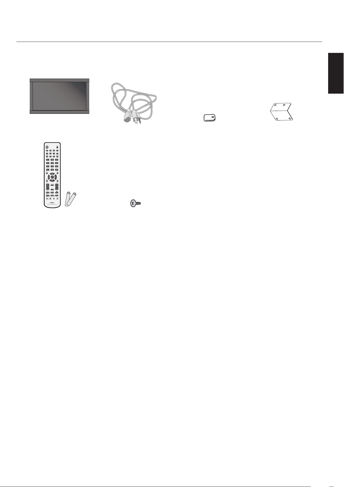
Package Contents
POWER
DVI VGA RGB/HV OPTION
HDMI
PICTURE
MODE
DISPLAY
AUTO
SET UP
VOL
STILL
PIP
REMOTEID
ON/OFF
SET RESET
REMOTE CONTROLLER RU-M111
MTS SLEEP
INPUT
CHANGE
ON/OFF
CAPTURE
MUTE
CH
CHRTN
EXIT
MENU
AUDIO
INPUT
DVD/HD
SIZE
SOUND
VIDEO
TV
GUIDE
1 2 3
4 5 6
7 809
ENT
SET
+
+ +
LCD Monitor Power Cord x 1 Clamp x 3 Main Switch Cover
English
Wireless Remote Control
and AA Batteries
Screw (M4 x 10 ) x 5
English-5
Installation
Unit
Mounting
Bracket
Thickness of
Bracket
Screw
10mm
Screw length should equal depth of
hole (10mm) + the thickness of
mounting bracket.
Mounting
DO NOT mount the monitor yourself. Please ask dealer.
•
For proper installation it is strongly recommended to
use a trained, qualied technician. Please inspect the
location where the unit is to be mounted. Not all walls
or ceilings are capable of supporting the weight of the
unit. Product warranty does not cover damage caused by
improper installation, remodeling, or natural disasters.
Failure to comply with these recommendations could
result in voiding the warranty.
DO NOT block ventilated openings with mounting
•
accessories or other accessories.
For NEC Qualied Personnel:
To insure safe installation, use two or more brackets to
mount the unit. Mount the unit to at least two points on the
installation location.
•
Allow adequate ventilation or provide air conditioning
around the monitor, so that heat can properly dissipate
away from the unit and mounting apparatus.
Mounting on Ceiling
Ensure that the ceiling is sturdy enough to support the
•
weight of the unit and the mounting apparatus over
time, against earthquakes, unexpected vibrations, and
other external forces.
Be sure the unit is mounted to a solid structure within
•
the ceiling, such as a support beam. Secure the monitor
using bolts, spring lock washers, washer and nut.
DO NOT mount to areas that have no supporting
•
internal structure. DO NOT use wood screws or anchor
screws for mounting. DO NOT mount the unit to trim
or to hanging xtures.
Please note the following when mounting
on wall or ceiling.
When using mounting accessories
•
other than those that are NEC
approved, they must comply with
the VESA-compatible (FDMlv1)
mounting method.
NEC strongly recommends using
•
size M6 screws (10mm + thickness
of bracket in length). If using
screws longer than 10mm, check the depth of the hole.
(Recommended Fasten Force: 470 - 635N
·cm) NEC
recommends mounting interfaces that comply with
UL1678 standard in North America.
Prior to mounting, inspect the installation location to
•
insure that it is strong enough to support the weight of
the unit so that the unit will be safe from harm.
Refer to the instructions included with the mounting
•
equipment for detailed information.
Mounting location
e ceiling and wall must be strong enough to support the
monitor and mounting accessories.
Maintenance
Periodically check for loose screws, gaps, distortions,
•
or other problems that may occur with the mounting
apparatus. If a problem is detected, please refer to
qualied personnel for service.
Regularly check the mounting location for signs of
•
damage or weakness that may occur over time.
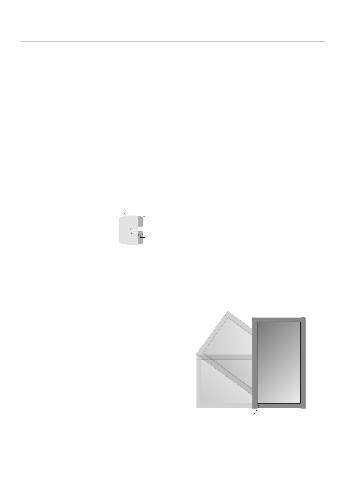
Orientation
When using the display in the portrait position, the monitor
should be rotated clockwise so that the le side is moved to
the top and the LED indicator light is on the bottom. is
will allow for proper ventilation and will extend the lifetime
of the monitor. Improper ventilation may shorten the
lifetime of the monitor.
DO NOT install in locations where a door or gate can
•
hit the unit.
DO NOT install in areas where the unit will be
subjected to strong vibrations and dust.
DO NOT install near where the main power supply
enters the building.
Do not install in where people can easily grab and hang
•
onto the unit or the mounting apparatus.
When mounting in a recessed area, as in a wall, leave at
•
least 4 inches (10cm) of space between the monitor and
the wall for proper ventilation.
LED Indicator
English-6
Installation - continued
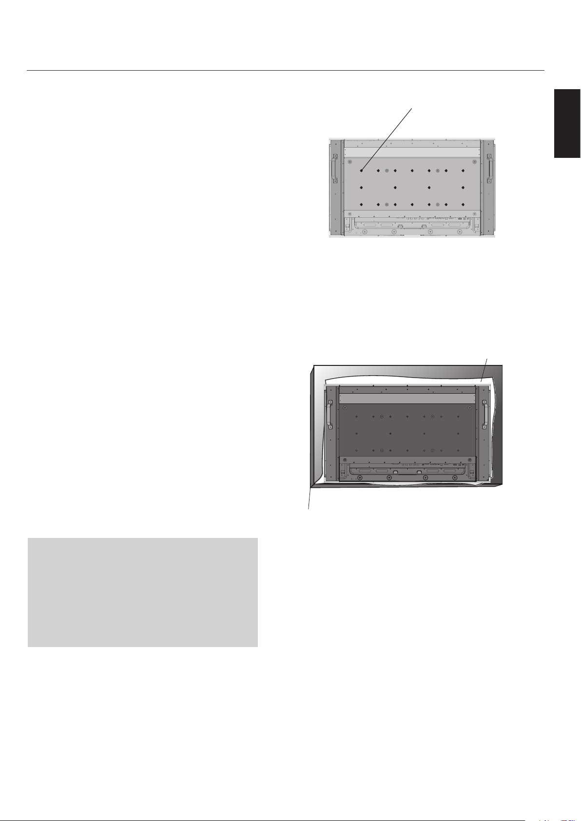
Attaching Mounting Accessories
e display is designed for use with the VESA mounting
system.
1) Attach Mounting Accessories
Mounting accessories can be attached while the monitor
is on a Tabletop Stand (optional) in the upright position
(Figure 1). Be careful to avoid tipping monitor when
attaching accessories. .
If no stand is available, mounting accessories can be
attached with the monitor in the face down position.
To avoid damaging the screen face, place the protective
sheet on the table underneath the LCD. e protective
sheet was wrapped around the LCD in the original
packaging. Make sure there is nothing on the table that
can damage the monitor.
When using mounting accessories other than NEC
compliant and approved, they must comply with the
VESA-compatible mounting method. NEC strongly
recommends using screws M6 size and 10mm in length.
If using screws longer than 10mm, check the depth of
the hole. (Recommended Fasten Force: 470-635N•cm)
NEC recommends using mounting interface that
comply with UL1678 standard in North America.
VESA Mounting Interface
Figure 1
English
Figure 2
Protective Sheet
For proper installation it is strongly recommended to
use a trained, NEC authorized service person. Failure
to follow NEC standard mounting procedures could
result in damage to the equipment or injury to the user
or installer. Product warranty does not cover damage
caused by improper installation. Failure to follow these
recommendations could result in voiding the warranty.
Table
English-7

Installation - continued
250mm
2) Ventilation Requirements
When mounting in an enclosure or in a recessed area,
leave space between surrounding the monitor and
surrounding objects to allow heat to disperse, as shown
in Figure 3.
3) Main Power Switch Cover
e Main Switch Cover will be attached in one of two
ways, depending on the orientation of the monitor.
When the Main Switch Cover is used when a Tabletop
Stand (optional) is attached, the longer side of the cover
will go underneath. When used without a stand, the
short side of the cover will go underneath (Figure 4).
4) Prevent Tipping
When using the display with the optional Tabletop
Stand fasten the LCD to a wall using a cord or chain
that can support the weight of the monitor (SC40
approx. 32.6kg; SC46 approx. 39.3kg) in order to
prevent the monitor from falling. Fasten the cord or
chain to the monitor using the provided clamp and
screw (Figure 5).
Before attaching the LCD monitor to the wall, make
sure that the wall can support the weight of the
monitor.
Be sure to remove the cord or chain from the wall
before moving the LCD.
Figure 3
Figure 4
Main switch cover
(with optional stand)
The longer side of the
cover is toward the
bottom of the display.
Main switch cover
(without optional stand)
The shorter side of the
cover is toward the bottom
of the display.
Screw Holes
Figure 5
Cord or Chain
Clamp
Screw
English-8
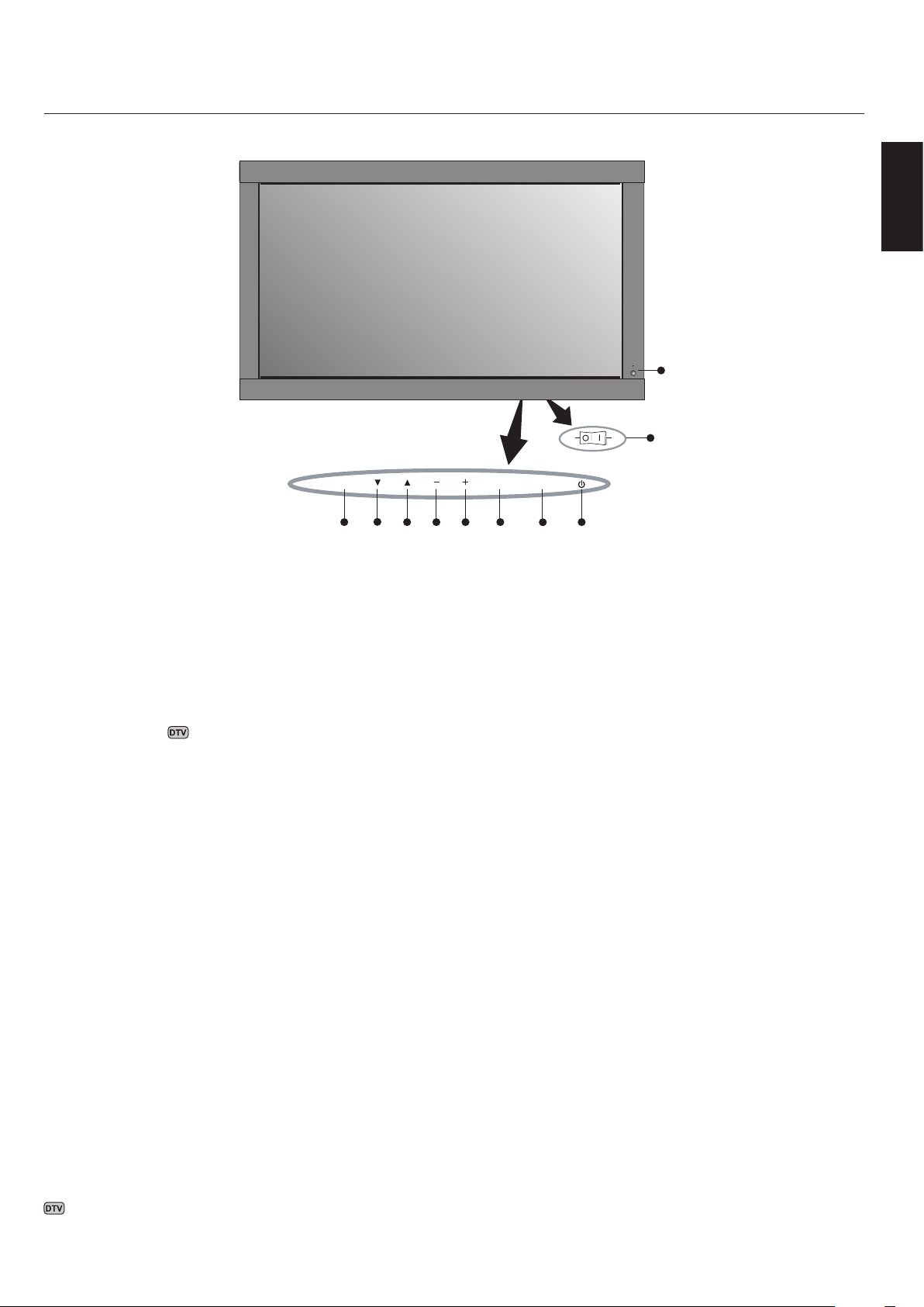
Control Panel
ONOFF
8 1234
5
67
EXIT MUTEINPUT
9
10
Part Names and Functions
English
Control Buttons and Main Power
Switch are located underneath and
behind the bezel.
1) POWER
Switches the power on/o. See page 23.
2) MUTE
Switches the audio mute ON/OFF.
3) INPUT
Selects which signal connected to the display is shown.
([DVI], [VGA], [RGB/HV], [HDMI], [DVD/HD],
[VIDEO], [TV] )
Acts as SET button within the OSD menu.
4) PLUS (+)
Increases the setting adjustment within OSD menu.
Increases the audio output level when the OSD is o.
5) MINUS (-)
Decreases the setting adjustment within OSD menu.
Decreases the audio output level when the OSD is o.
6) UP (▲)
Activates the OSD menu when the OSD menu is o.
Moves the highlighted area up to select which setting to be
adjust within OSD menu.
7) DOWN (▼)
Activates the OSD menu when the OSD menu is o.
Moves the highlighted area down to select which setting to
be adjust within OSD menu.
8) EXIT
Activates the OSD menu when the OSD menu is o.
Exits from the current menu being displayed to the
previous menu within the OSD.
9) Remote control sensor and Power indicator
Receives the signal when using the wireless remote control.
See page 14.
Glows green when the LCD monitor is in active mode.
Glows red when the LCD is in POWER OFF (ECO standby)
mode*. Glows Amber when the LCD is in POWER OFF
(standby) mode. Amber blinks when the monitor is in
Power Save Mode. Green and Amber blink alternately
while in Power Standby with the “SCHEDULE SETTINGS”
function enabled. When a component failure is detected
within the monitor, the indicator will blink red.
"*If "OFF" is selected in POWER INDICATOR(See page 26),
the LED will not light when the LCD monitor is active mode".
10) Main Power Switch
Seesaw Switch for the main power on/o.
Control Key Lock Mode
is function completely locks out access to all Control Key
functions.
To enable the Control Key Lock Mode, press both “▲” and
“▼” buttons simultaneously and hold down for three (3)
seconds.
To go back to user mode, press both ““▲” and “▼” buttons
simultaneously and hold down for three (3) seconds.
Denotes Optional Digital Tuner function.
English-9
Part Names and Functions - continued
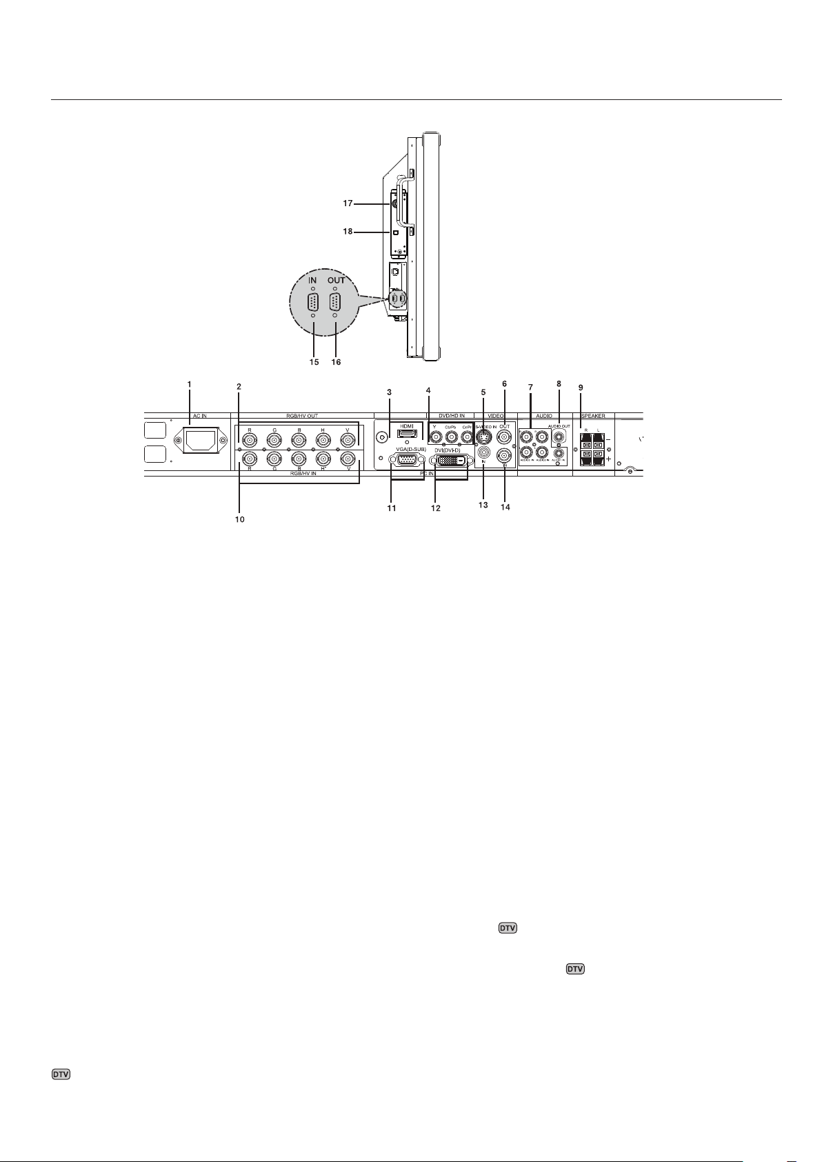
Terminal Panel
1) AC IN
Connects with the supplied power cord.
2) RGB/HV OUT [R, G, B, H, V] (BNC)
Outputs the signal from the RGB/HV IN connector to an
input on a separate device.
3) HDMI
To input digital HDMI signals.
4) DVD/HD IN
Connecting equipment such as a DVD player, HDTV
device, or Set-Top-Box.
5) S-VIDEO IN
Input S-video.
6) VIDEO OUT
Output the composite video signal from the VIDEO IN
connection.
7) AUDIO IN
Input the audio signal from external equipment such as a
computer, VCR or DVD player.
8) AUDIO OUT
Output the audio signal from the AUDIO IN 1, 2, 3,
HDMI, and TV jack to an external device (stereo receiver,
amplier, etc,).
10) RGB/HV IN [R, G, B, H, V] (BNC)
Input RGB/HV signals or signals from other RGB
equipment. A Sync-on-Green signal can be connected to
the G connector.
11) VGA (mini D-SUB15)
Analog computer input.
12) DVI-D
Input digital RGB signals from a computer or HDTV
device having a digital RGB output.
13) VIDEO IN (RCA)
Composite video input.
14) VIDEO IN (BNC)
Composite video input.
15) EXTERNAL CONTROL (D-Sub 9 pin)
Connect RS-232C input to external equipment such as a
PC in order to control RS-232C functions.
16) EXTERNAL CONTROL (D-Sub 9 pin)
Connect RS-232C output.
To connect to multiple MultiSync SC monitors
via daisy RS-232C Chain.
17) RF IN
TV signal input.
9) SPEAKER TERMINALS
Output the audio signal from AUDIO 1, 2, 3, HDMI, and
TV to external speakers jack.
NOTE: Speaker Terminal for 15W + 15W (8 ohm).
Denotes Optional Digital Tuner function.
18) S/PDIF OUTPUT
English-10
Optical digital audio out.
Part Names and Functions - continued
POWER
DVI VGA RGB/HV OPTION
HDMI
PICTURE
MODE
DISPLAY
AUTO
SET UP
VOL
STILL
PIP
REMOTE ID
ON/OFF
SET RESET
REMOTE CONTROLLER RU-M111
MTS SLEEP
INPUT
CHANGE
ON/OFF
CAPTURE
MUTE
CH
CH RTN
EXIT
MENU
AUDIO
INPUT
DVD/HD
SIZE
SOUND
VIDEO
TV
GUIDE
1 2 3
4 5 6
7 8
0
9
ENT
SET
+
+ +
1
2
3
4
6
7
5
8
11
9
13
18
14
15
16
17
19
21
23
24
22
25
26
20
10
12
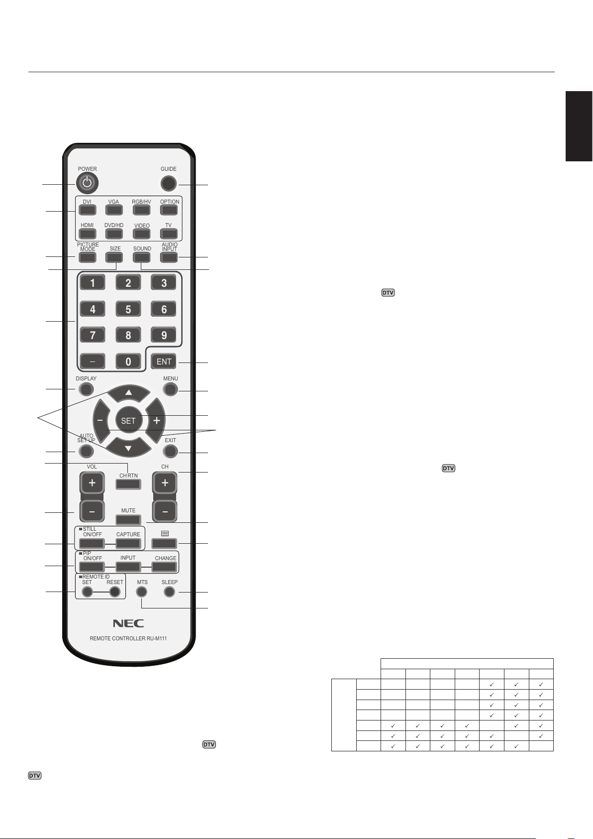
Remote Control Functions
3) PICTURE MODE
Selects picture mode, [HIGHBRIGHT], [STANDARD],
[sRGB], [CINEMA]. See page 24.
HIGHBRIGHT: for moving images
STANDARD: for images
sRGB: for text based images
CINEMA: for movies
4) SIZE
Selects aspect ratio of the displayed image.
[FULL], [NORMAL], [WIDE], and [ZOOM]. See page
25.
5) KEYPAD
Set and change passwords. Set REMOTE ID.
Select TV channel.
6) DISPLAY
Turn on/o the Information OSD. See page 24.
7) ▲ ▼
Move highlighted area up or down.
Moves the PIP sub-picture.
8) AUTO SETUP
Enters AUTO SETUP menu.
English
1) POWER
2) INPUT
Switches the power on/o.
Selects which input signal ([DVI], [VGA], [RGB/HV],
[HDMI], [DVD/HD], [ VIDEO], [TV] , [OPTION])
to be displayed.
Denotes Optional Digital Tuner function.
9) CHANNEL RETURN
Return to previous channel.
10) VOLUME
Increases or Decreases sound level.
11) STILL
ON/OFF: Activates/deactivates still picture mode.
CAPTURE: Captures still picture.
12) PICTURE in PICTURE
ON/OFF: Turns PIP on or o.
INPUT: Changes the input signal of PIP.
CHANGE: Swaps inner picture with outer picture.
Sub Picture
DVI VGA RGB/HV HDMI DVD/HD VIDEO TV
DVI - - - -
VGA - - - -
RGB/HV - - - -
Main
HDMI - - - -
Picture
DVD/HD -
VIDEO -
TV -
English-11

Part Names and Functions - continued
13) REMOTE ID
Activates REMOTE ID function. See page 15.
14) GUIDE
Enter on screen program guide.
15) AUDIO INPUT
Select the Audio source.
NOTE: It is possible to play audio from a source that is
dierent from the video source. When setting parental
controls for video, be aware that this content is not
ltered.
16) SOUND
Articial surround sound.
17) ENTER
Go to channel selected.
18) MENU
Turns ON/OFF menu mode.
19) SET
Makes selection.
Changing the channel
Both Analog and Digital channels are available using this
tuner. In addition to the CH+ and CH- buttons channels can
be changed in the following method.
Tuning Analog Channels
Input the desired channel number using the keypad, then
press [SET] or [ENT] to immediately tune to the new channel. If the number is input and [SET] or [ENT] is not pushed,
aer a few seconds the channel will be changed. For example
to tune to channel 5, press [5] then press [SET] or [ENT].
Tuning Digital Channels
To tune in to a digital sub-channel enter the number of the
main channel, then a dash followed by the number of the
sub-channel. For example to tune to digital channel 5-1,
press [5] then [–] then [1]. Press [SET] or [ENT] to tune.
20) - , +
Increases or decreases adjustment.
Moves the PIP sub-picture.
21) EXIT
Goes to previous menu.
22) Channel
Go up or down channel selections.
23) MUTE
Mutes audio output.
24)
Activates closed captioning.
25) SLEEP
Sleep timer.
26) MTS
Multi-track sound.
Denotes Optional Digital Tuner function.
English-12
30
30
POWER
DVI VGA RGB/HV OPTION
HDMI
PICTURE
MODE
DISPLAY
AUTO
SET UP
VOL
STILL
PIP
REMOTEID
ON/OFF
SET RESET
REMOTE CONTROLLER RU-M111
MTS SLEEP
INPUT
CHANGE
ON/OFF
CAPTURE
MUTE
CH
CHRTN
EXIT
MENU
AUDIO
INPUT
DVD/HD
SIZE
SOUND
VIDEO
TV
GUIDE
1 2 3
4 5 6
7 809
ENT
SET
+
+ +
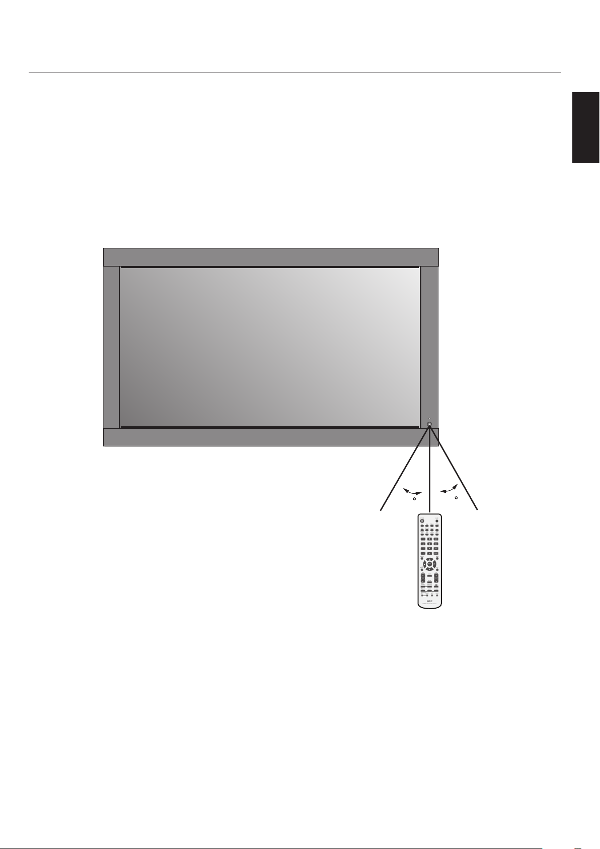
Remote Control Operating Range
Operating Range for the Remote Control
Point the top of the remote control toward the monitor’s
remote sensor while pressing buttons. e remote control
can be used from the front of the monitor at a maximum
distance of 7 m/23 . from the front of the LCD monitor’s
remote control sensor. e maximum horizontal and
vertical angle for use of the remote is 30 degrees within a
distance of 3.5 m/10 .
Part Names and Functions - continued
English
CAUTION
e remote control system may not function when direct
sunlight or strong illumination strikes the remote control
sensor of the LCD monitor, or when there is an object in
the path of the sensor.
Handling the Remote Control
Do not open the remote control other than to
install batteries.
Do not allow water or other liquid to splash onto the
remote control. If the remote control gets wet, wipe it dry
immediately.
Avoid exposure to heat and steam.
English-13
POWER
DVI VGA RGB/HV OPTION
HDMI
PICTURE
MODE
DISPLAY
AUTO
SET UP
VOL
STILL
PIP
REMOTEID
ON/OFF
SET RESET
REMOTE CONTROLLER RU-M111
MTS SLEEP
INPUT
CHANGE
ON/OFF
CAPTURE
MUTE
CH
CHRTN
EXIT
MENU
AUDIO
INPUT
DVD/HD
SIZE
SOUND
VIDEO
TV
GUIDE
1 2 3
4 5 6
7 809
ENT
SET
+
+ +
POWER
DVI VGA RGB/HV OPTION
HDMI
PICTURE
MODE
DISPLAY
AUTO
SET UP
VOL
STILL
PIP
REMOTEID
ON/OFF
SET RESET
REMOTE CONTROLLER RU-M111
MTS SLEEP
INPUT
CHANGE
ON/OFF
CAPTURE
MUTE
CH
CHRTN
EXIT
MENU
AUDIO
INPUT
DVD/HD
SIZE
SOUND
VIDEO
TV
GUIDE
1 2 3
4 5 6
7 809
ENT
SET
+
+ +
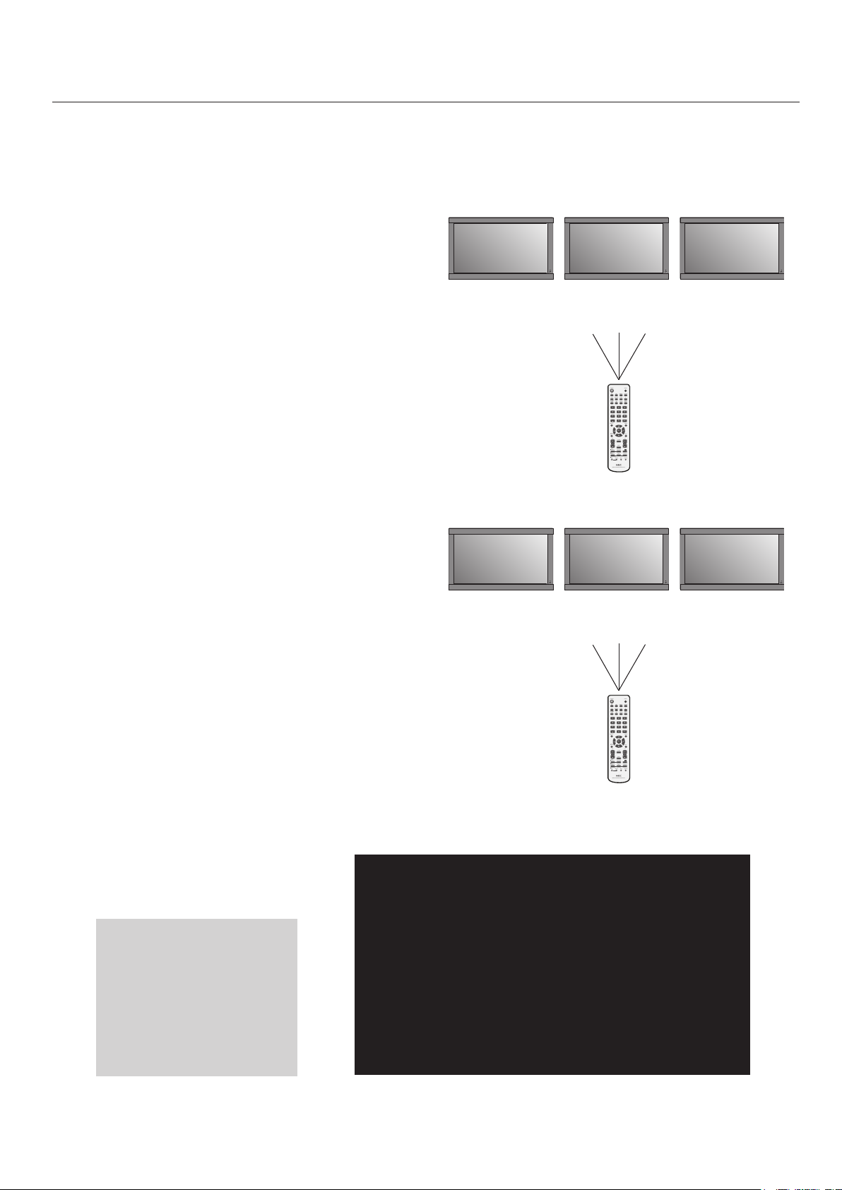
Part Names and Functions - continued
REMOTE CONTROL ID
e remote control included with the display can be used
to control up to 26 individual MultiSync SC monitors using
what is called the REMOTE CONTROL ID mode. e REMOTE CONTROL ID mode works in conjunction with the
Monitor ID, allowing control of up to 26 individual MultiSync SC monitors. For example: if there are many monitors
being used in the same area, a remote control in normal
mode would send signals to every monitor at the same
time Figure 1. Using the remote in REMOTE CONTROL
ID mode will only operate one specic monitor within the
group Figure 2.
Remote works Remote works Remote works
Remote Control ID Function
Monitor ID:1 Monitor ID:2 Monitor ID:3
TO SET REMOTE CONTROL ID:
While holding down the REMOTE ID SET button on the
remote control, use the KEYPAD to input the Monitor ID
(1-26) of the display to be controlled via remote. e remote
can then be used to operate the monitor having that specic
Monitor ID number.
When 0 is selected or when the remote control is in normal
mode, all monitors will be operated.
TO USE REMOTE CONTROL ID MODE
ID Mode - To enter ID Mode press the REMOTE ID SET
button and hold down for 2 seconds.
Normal Mode - To return to Normal Mode press the
REMOTE ID RESET button and hold down for 2 seconds.
In order for this feature to work properly, the display must be
assigned a Monitor ID number. e Monitor ID number can
be assigned under the MULTI DISPLAY menu in the OSD
See page 29.
Figure 1
Remote in Normal
mode or the REMOTE
ID is set to 0
Monitor ID:1 Monitor ID:2 Monitor ID:3
Remote does
not work
Remote does
not work
Remote works
Figure 2
Remote set up to
use Remote ID:3
ID number assigned to display
Press the “DISPLAY” button
on the remote to bring up
the Information OSD. e
Information OSD shows the
monitor ID number and other
information such as signal
type, zoom method, etc.
Monitor ID:1
Target ID:5
English-14
INFORMATION OSD
DVI
AUDIO:IN1
SIZE:FULL
1024 X 768
48KHz/60Hz

Setup
Please see installation on page 6 of
this manual and follow all installation
instructions.
1) Determine the installation location.
CAUTION: Installing your LCD display must be
done by a qualied technician. Contact your dealer for
more information.
CAUTION: MOVING OR INSTALLING THE LCD
MONITOR MUST BE DONE BY TWO OR MORE
PEOPLE. Failure to follow this caution may result in
injury if the LCD monitor falls.
CAUTION: Do not mount or operate the display
upside down, face up, or face down.
CAUTION: is LCD has a temperature sensor
and cooling fan. If the LCD becomes too hot, the
cooling fan will turn on automatically. If the LCD
becomes overheated while the cooling fan is running,
the “Caution” menu will appear. If the “Caution”
menu appears, discontinue use and allow the unit to
cool. Using the cooling fan will reduce the likelihood
of early circuit failure and may help reduce image
degradation and " image persistance".
If the LCD is used in an enclosed area or if the LCD
panel is covered with a protective screen, please check
the inside temperature of the monitor by using the
“HEAT STATUS” control in the OSD See page 29). If
the temperature is higher than the normal operating
temperature, please turn the cooling fan to ON within
the FAN CONTROL menu within the OSD
See page 29).
2) Install the remote control batteries.
e remote control is powered by two 1.5V AA
batteries. To install or replace batteries:
A. Press and slide to open the cover.
B. Align the batteries according to the (+)
and (–) indications inside the case.
C. Replace the cover.
CAUTION: Incorrect usage of batteries can result
in leaks or bursting. NEC recommends the following
battery use:
Place “AA” size batteries matching the (+) and (-) signs
•
on each battery to the (+) and (-) signs of the battery
compartment.
Do not mix battery brands.
•
Do not combine new and old batteries. is can shorten
•
battery life or cause liquid leakage of batteries.
Remove dead batteries immediately to prevent battery
•
acid from leaking into the battery compartment.
Do not touch exposed battery acid, it may injure skin.
•
NOTE: If you do not intend to use the Remote Control for
a long period of time, remove the batteries.
English
IMPORTANT
Lay the protective sheet, which was wrapped around the
LCD monitor when it was packaged, beneath the LCD
monitor so as not to scratch the panel.
English-15
Setup - continued
3) Connect external equipment.
To protect the external equipment, turn o the main
•
power before making connections.
Refer to your equipment user manual for further
•
information.
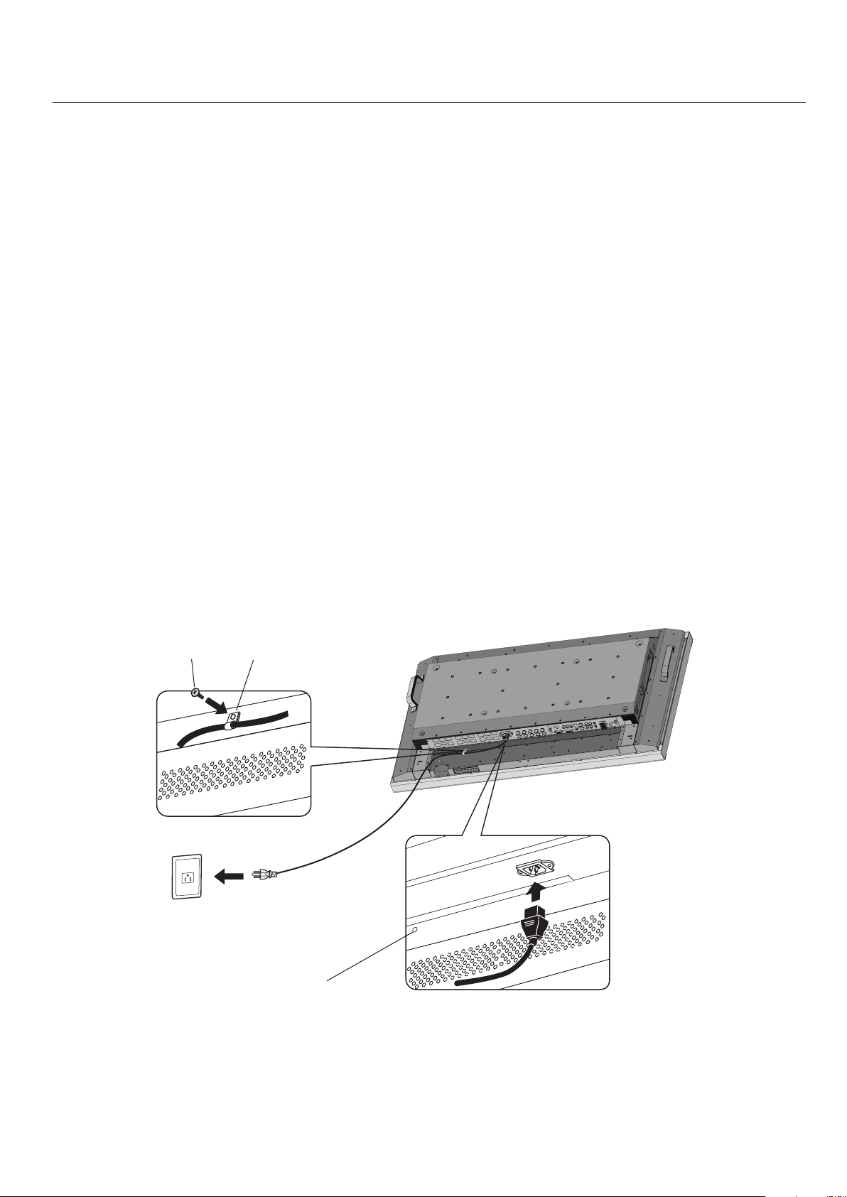
4) Connect the supplied power cord.
e equipment should be installed close to an easily
•
accessible power outlet.
Please attach power cord to the LCD monitor by
•
attaching the screw and clamp.
Fully insert the prongs into the power outlet socket. A
•
loose connection may cause image degradation.
NOTE: If you use this monitor at AC 220 - 240V,
please refer to “Safety Precautions and Maintenance &
Recommended Use” sections of this manual for proper
selection of AC power cord.
5) Switch on the power of all the attached
external equipment.
When connected with a computer, switch on the power
of the computer rst.
6) Operate the attached external equipment.
Display the signal from the desired input source.
7) Adjust the sound
Make volume adjustments as required.
8) Adjust the screen See page 26.
Make adjustments of the screen display position when
necessary.
9) Adjust the image See page 26.
Make adjustments such as brightness or contrast when
required.
10) Recommended Adjustments
To reduce the risk of the “image persistence”, please
adjust the following items based on the application
being used:
“DATE & TIME” and “SCHEDULE SETTINGS”
See pages 27 and 28.
“SCREEN SAVER”, and “SIDE BORDER COLOR”
See page 29.
It is recommended that the “FAN CONTROL”
setting be turned to ON also. See page 30.
Screw Clamp
Screwhole for Clamp
English-16
Connections
AC IN RGB/HV OUT
PC IN
VIDEO
DVD/HD IN
AUDIO SPEAKER
RGB/HV IN
VGA(D-SUB)
DVI(DVI-D)
HDMI
Y Cb/Pb Cr/Pr
S-VIDEO IN
OUT
AUDIO OUT
R L
-
-
-
AUDIO1 INAUDIO2 INAUDIO3 IN
R R
L L
IN
IN
R G B H V
R G B H V
Before connecting external equipment to LCD:
First turn o the power to all of the equipment associated
with the LCD as well as that of the equipment to be
connected.
For questions regarding external equipment please refer to
the user’s manual supplied with that equipment.
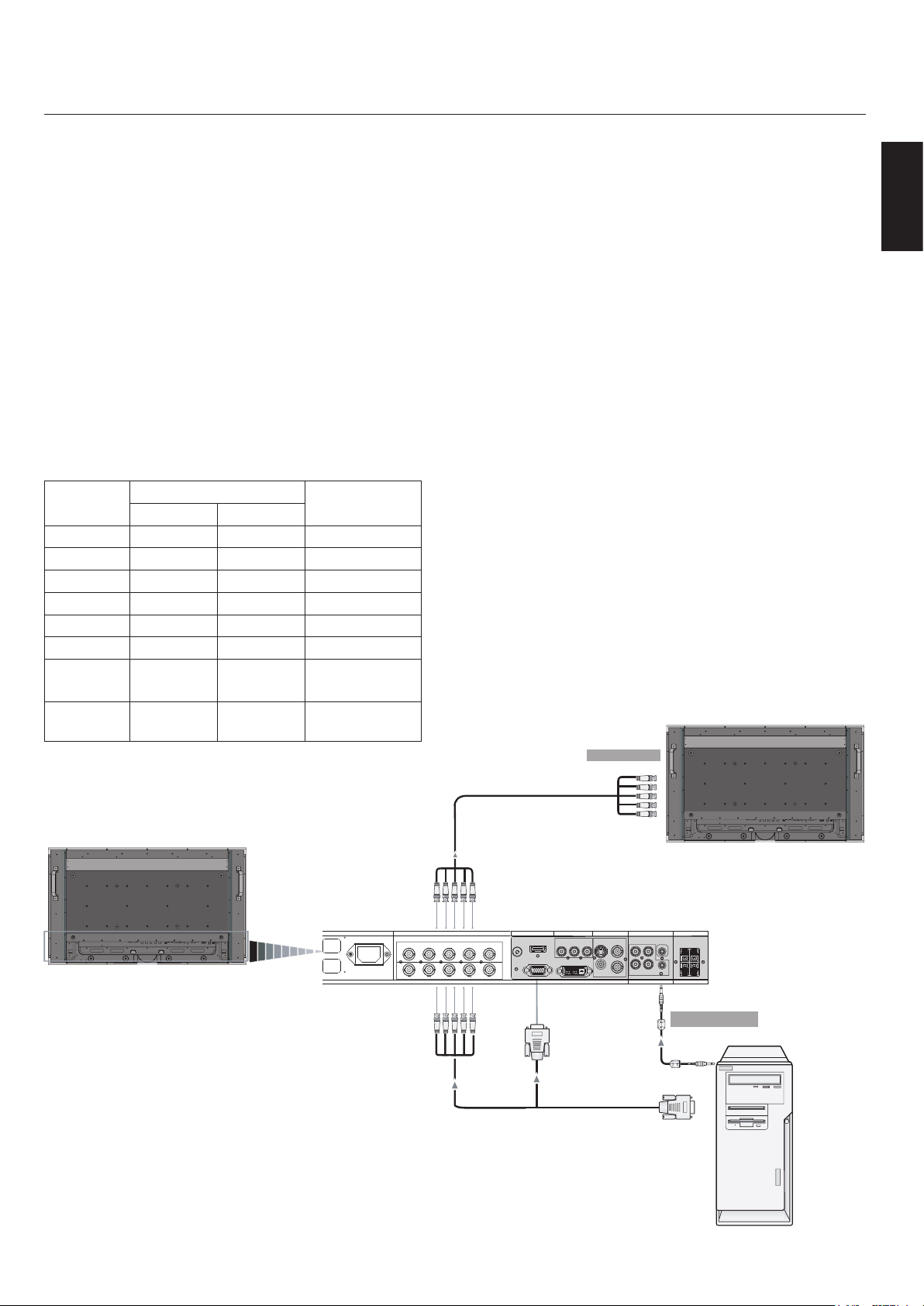
Connecting the LCD Monitor to a PC
Connecting your computer to your LCD monitor will enable
you to display your computer’s screen image.
Some video cards having a pixel clock over 162MHz may not
display images correctly.
e LCD monitor will automatically adjust to a preset
timing to display the proper image.
<Factory Preset Signal Timing>
Scanning frequency
Resolution
640x480 31.5kHz 60Hz
800x600 37.9kHz 60Hz
1024x768 48.4kHz 60Hz
1280x768 48.0kHz 60Hz
1360x768 48.0kHz 60Hz
1280x1024 64.0kHz 60Hz
1600x1200 75.0kHz 60Hz
1920x1080 66.6kHz 60Hz
Horizontal Vertical
Remarks
Compressed
image
Recommended
resolution
To connect to the VGA connector (mini D-sub 15 pin) on
the LCD monitor, use the provided RGB signal cable (mini
D-sub 15 pin to mini D-sub 15 pin).
To connect to the RGB/HV connector (BNC) on the LCD
monitor, use a mini D-sub 15 pin to BNC x 5 signal cable
(not included). Select RGB/HV from the INPUT button.
When connecting to a second LCD monitor, use the RGB/
HV OUT connector (BNC)(BNC Input only).
e AUDIO IN1, 2, 3 can be used to choose the audio
source. To select, use the AUDIO INPUT button.
To RGB/HV Input
BNC x 5
English
LCD Monitor
BNC x 5BNC x 5
English-17
(BNC Input only)
Mini D-sub 15 pin
From Analog RGB Output
From Audio Output
PC or IBM
compatible
LCD Monitor
(second monitor)
AC IN RGB/HV OUT
PC IN
VIDEO
DVD/HD IN
AUDIO SPEAKER
RGB/HV IN
VGA(D-SUB)
DVI(DVI-D)
HDMI
Y Cb/Pb Cr/Pr
S-VIDEO IN
OUT
AUDIO OUT
R L
-
-
-
AUDIO1 INAUDIO2 INAUDIO3 IN
R R
L L
IN
IN
R G B H V
R G B H V
Connections - continued
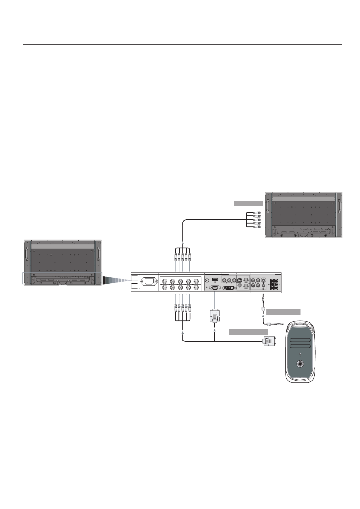
Connecting to a Macintosh® Computer
Connecting your Macintosh computer to your LCD
monitor will enable you to display your computer’s screen
image. Some video cards or drivers may not display images
correctly.
To connect to the VGA connector (mini D-sub 15 pin) on
the LCD monitor, use the RGB signal cable (mini D-sub 15
pin to mini D-sub 15 pin) included with the display.
NOTE: For older Macintosh computers, use Macintosh cable
adapter to connect to your Macintosh’s video port. To obtain
the Macintosh cable adapter call NEC Display Solutions of
America, Inc. at (800) 632-4662
To connect to the RGB/ HVconnector (BNC) on the LCD
monitor, use a mini D-sub 15 pin to BNC x 5 signal cable
(not included)(BNC Input only).
If you will be connecting the LCD monitor to a Macintosh
PowerBook, set “Mirroring” to o.
Refer to your Macintosh’s owner’s manual for more
information about your computer’s video output
requirements and any special identication or conguring
that may be required.
e AUDIO IN1, 2, 3 can be used to choose the audio
source. To select, use the AUDIO INPUT button.
To RGB/HV Input
BNC x 5
(BNC Input only)
LCD Monitor
BNC x 5BNC x 5
Mini D-sub 15 pin
From Analog RGB Output
Mini D-sub 15 pin
(second monitor)
From Audio Output
Macintosh
LCD Monitor
English-18

Connecting to a Computer with Digital Output
AC IN RGB/HV OUT
PC IN
VIDEO
DVD/HD IN
AUDIO SPEAKER
RGB/HV IN
VGA(D-SUB)
DVI(DVI-D)
HDMI
Y Cb/Pb Cr/Pr
S-VIDEO IN
OUT
AUDIO OUT
R L
-
-
-
AUDIO1 INAUDIO2 INAUDIO3 IN
R R
L L
IN
IN
R G B H V
R G B H V
Connections can be made with devices equipped with a
digital interface that complies with the DVI (Digital Visual
Interface) standard.
DVI connector also accepts a DVI-D cable.
•
Input TMDS signals conforming to DVI standards.
•
To maintain display quality, use a cable recommended
•
by DVI standards.
e AUDIO IN1, 2, 3 can be used to choose the audio
source. To select, use the AUDIO INPUT button.
Connections - continued
Equipment with a digital interface such as
a PC with RGB output (TMDS)
English
LCD Monitor
From DVI output
DVI-D connector
English-19
Connections - continued
Connecting a DVD Player with component out
Connecting your DVD player to your LCD monitor will
enable you to display DVD video.
Refer to your DVD player user’s manual for more
information.
Connect the LCD Monitor to a DVD Player
To connect the DVD/HD IN connector (RCA) on the
•
LCD monitor, use a separately available RCA connector
cable.
Some DVD players may have dierent connectors such
•
as a DVI-D connector.
Select [DVI/HD] mode from the “DVI MODE” menu
•
when you connect a DVI-D connector. For DVI Mode
selection, see “DVI MODE” on page 30.
e AUDIO IN1, 2, and 3 (both RCA) can be used for
•
audio input. For connection, select [IN1, IN2] or [IN3]
from the AUDIO INPUT button.
To DVI Output
Left Audio
Right Audio
From DVD Compononent
Video Output
DVI-D Connector
RCA
RCA
LCD Monitor
RCA
English-20
Connections - continued
RGB/HV OUT
RGB/HV IN
VGA (D-SUB) DVI (DVI-D)
RGB/HV OUT
RGB/HV IN
VGA (D-SUB) DVI (DVI-D)
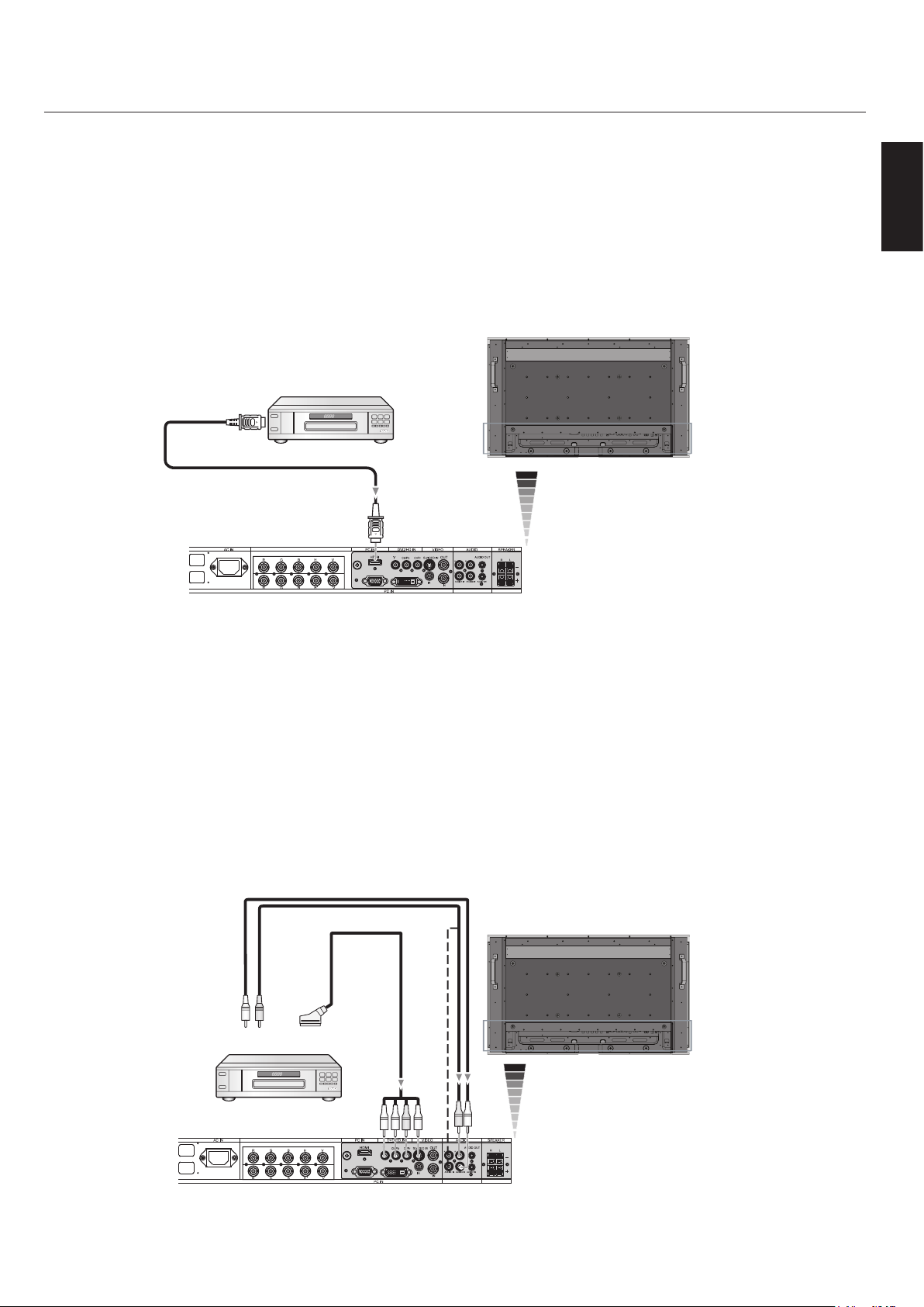
Connecting a DVD Player with HDMI out
Connecting your DVD player to your LCD monitor will enable you to display DVD video.
Refer to your DVD player user’s manual for more information.
Connect the LCD Monitor to a DVD Player
Please use an HDMI cable that has the HDMI logo.
•
It may take a few seconds to show the signal.
•
We do not support PC-DVI signals.
•
LCD Monitor
From HDMI Output
HDMI Connector
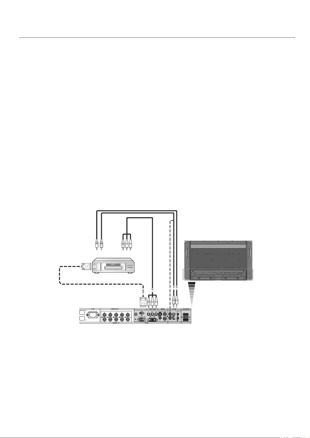
Connecting a DVD Player with SCART out
Connecting your DVD player to your LCD monitor will enable you to display SCART.
Connect the LCD Monitor to a DVD Player
To connect the DVD/HD IN connector (RCA) on the LCD monitor and connect the video (sync) and the Video In connector
•
(RCA), use a separately available RCA connector cable.
Some DVD players may have dierent connectors such as DVI-D connector.
•
Select [ON] mode from the “SCART MODE” menu when you use a SCART connector. For Mode selection, see “SCART” on
•
page 30.
e AUDIO IN 2 and 3 (both RCA) can be used for audio input. For connection, select [IN2] or [IN3] from the AUDIO
•
INPUT button.
English
Left Audio
Right Audio
To DVD Component
video output
LCD Monitor
SCART
RCA
RCA
English-21
Connections - continued
RGB/HV OUT
RGB/HV IN
VGA (D-SUB) DVI (DVI-D)
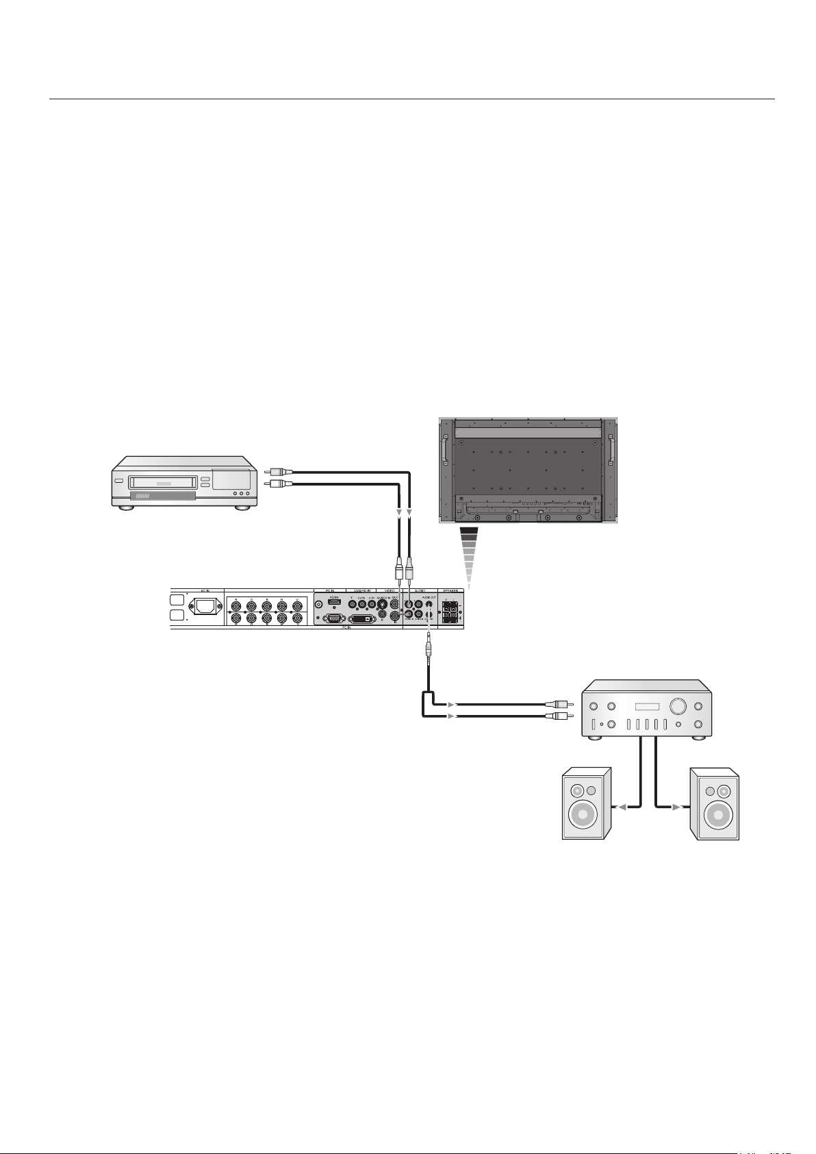
Connecting to a Stereo Amplier
You can connect your stereo amplier to your LCD monitor. Refer to your amplier owner’s manual for more information.
Connect the LCD Monitor to a Stereo Amplier
Turn on the LCD monitor and the amplier only aer all connections have been made.
•
Use a Stereo Mini-RCA cable to connect the AUDIO OUT connector (Stereo Mini-RCA) on the LCD monitor and the audio
•
input on the amplier.
Do not reverse the audio le and right jacks.
•
e AUDIO IN is used for audio input.
•
e AUDIO OUT jack outputs sound from the selected Audio input.
•
LCD Monitor
To Audio Right
VCR or Laser disc player
To Audio Left
RCA
To Audio Right
To Audio Left
Amplifier
External
Speakers
English-22
OFFON
e LCD monitor power indicator will turn green while
30
30
POWER
DVI VGA RGB/HV OPTION
HDMI
PICTURE
MODE
DISPLAY
AUTO
SET UP
VOL
STILL
PIP
REMOTEID
ON/OFF
SET RESET
REMOTE CONTROLLER RU-M111
MTS SLEEP
INPUT
CHANGE
ON/OFF
CAPTURE
MUTE
CH
CHRTN
EXIT
MENU
AUDIO
INPUT
DVD/HD
SIZE
SOUND
VIDEO
TV
GUIDE
1 2 3
4 5 6
7 809
ENT
SET
+
+ +
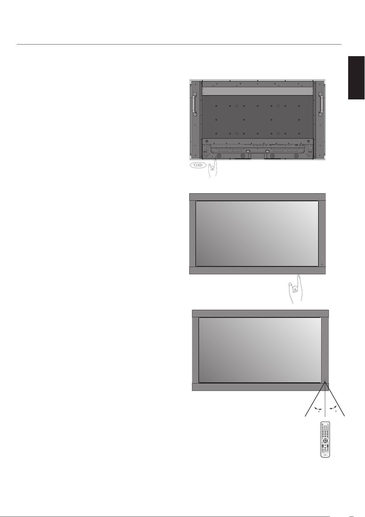
powered on and will turn red or Amber while powered o.
NOTE: e Main Power Switch must be in the ON position
in order to power up the monitor using the remote control
or the Power Button on the front of the LCD.
Basic Operation - Power ON and OFF Modes
English
Main Power Switch
Power Button
English-23
STANDARD sRGB HIGHBRIGHT
STANDARD CINEMA HIGHBRIGHT
DVI, VGA,
RGB/HV, OPTION
HDMI, DVD/HD,
VIDEO, TV
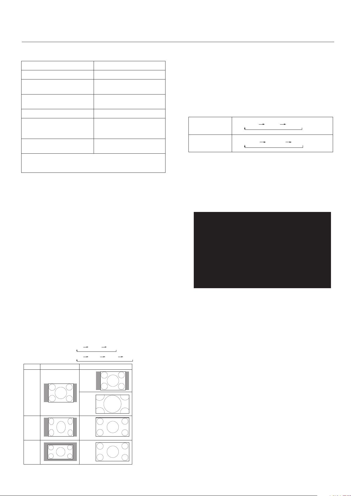
Basic Operation - continued
Signal Type
4:3
NORMAL SIZE RECOMMENDED SIZE
NORMAL
ZOOM
(DYNAMIC)
FULL
WIDE
Squeeze
Letterbox
DVI, VGA, RGBH/V, OPTION FULL ZOOM NORMAL
FULL WIDE ZOOM NORMAL
HDMI, DVD/HD, VIDEO, TV
Power Indicator
Mode Status Indicator Light
Power ON Green*2
Power OFF (ECO STANDBY)*
Power consumption under 1W
Power OFF (STANDBY)
Power consumption under 5W
Power Save Amber Blinking
Power Standby when
“SCHEDULE SETTINGS”
enabled
Diagnosis (Detecting faiure) Red Blinking
*When in Eco Standby Mode RS-232C controls do not function.
*2 If "OFF" is selected in POWER INDICATOR(See page 26), the LED will
not light when the LCD monitor is active mode"
Red
Amber
Green and Amber
blink alternately
(See Trouble Shooting page 41)
Power Management
e LCD monitor follows the VESA approved DPM Power
Management function.
e power management function is an energy saving
function that automatically reduces the power consumption
of the display when the keyboard or the mouse has not been
used for a xed period of time.
e power management feature on your new display has
been set to the “ON” mode. is allows your display to enter
a Power Saving Mode when no signal is detected. is could
potentially increase the lifetime of the display while power
consumption is decreased.
Picture Mode
Choose the Picture Mode that is most suitable for the type of
content that is shown.
Standard: for images
sRGB: For text based applications.
Highbright: for moving images
Cinema: for movies
Information OSD
e Information OSD provides information such as: Monitor
ID, Input Source, Picture Size, etc. Press the DISPLAY button
on the remote to bring up the Information OSD.
See page 34 for detailed explanation.
Monitor ID:1
Target ID:5
DVI
AUDIO: IN1
SIZE:FULL
1024 X 768
48KHz/60Hz
STANDBY mode is used when the display is connected to an
RS-232C cable or when using the INPUT DETECT function.
ECO STANDBY uses less power, but the RS-232C and
INPUT DETECT functions are not available.
Picture Size
e size of the picture can be changed depending on the
aspect ratio (4:3, 16:9, etc.) of the input signal.
English-24

OSD (On-Screen-Display) Controls
ADAPTIVE CONTRASTADAPTIVE CONTRAST
(PUP-JTU
(PUP"EKVTUNFOU
DVI
ADAPTIVE CONTRAST
Input Source
Main Menu Icons
Main Menu Items
Remote
Control
Sub Menu
Press UP or DOWN
button to select
sub-menu.
Press
SET.
Key Guide
Press UP, DOWN, PLUS,
or MINUS to select the
function or setting to be
adjusted.
English
Adjustment
Settings
Press MENU or
EXIT.
Control
Panel
Press UP or DOWN
button to select.
OSD
Screen
Press INPUT button
to decide.
English-25
Press UP, DOWN,
PLUS, or MINUS to
select.
Press
EXIT.

OSD Controls - continued
OSD
PICTURE BRIGHTNESS Adjusts the overall image and background brightness. Press + or - to adjust.
Setting
CONTRAST Adjusts the image brightness in relationship to the background. Press + or - to adjust.
SHARPNESS Adjusts the crispness of the image. Press + or - to adjust.
BLACK LEVEL Adjusts the image brightness in relationship to the background. Press + or - to adjust.
TINT
HDMI, DVD/HD, VIDEO, TV
input only
COLOR
HDMI, DVD/HD, VIDEO, TV
input only
COLOR TEMPERATURE Adjusts the color temperature of the entire screen. A low color temperature will make
COLOR CONTROL
DVI, VGA, RGB/HV, HDMI
input only
GAMMA SELECTION
NATIVE
2.2
2.4
S GAMMA
DICOM SIM.
PROGRAMMABLE
Note: The sRGB picture mode is standard and cannot be changed.
Note: The sRGB picture mode is standard and cannot be changed.
Adjusts the tint of the screen. Press + or - to adjust.
Adjusts the color depth of the screen. Press + or - to adjust.
the screen reddish. A high color temperature will make the screen bluish.
Note: The sRGB picture mode is set to a predened 6500 K standard
and connot be changed.
Adjusts the levels of the Red, Yellow, Green, Cyan, Blue, Magenta and Saturation.
Note: The sRGB picture mode is standard and cannot be changed.
Select a display gamma for best picture quality.
Note: The sRGB picture mode is standard and cannot be changed.
Gamma correction is handled by the LCD panel.
Typical display gamma for use with a PC.
Good for video (TV, DVD, etc.).
Special gamma for certain types of movies. Raises the dark parts and lowers the
light parts of the image. (S-Curve)
DICOM GSDF curve simulated for LCD type.
A programmable gamma curve can be loaded using NEC software.
ADAPTIVE CONTRAST
HDMI, DVD/HD, VIDEO, TV
input only
OFF
MID
HIGH
MOVIE SETTINGS
NOISE REDUCTION
VIDEO, TV input only
FILM MODE
HDMI, DVD/HD, VIDEO, TV
input only
PICTURE RESET Resets the following settings within the PICTURE menu back to factory setting:
ADJUST AUTO SETUP
VGA and RGB/HV input only
AUTO ADJUST
VGA and RGB/HV input only
H POSITION
V POSITION
Sets the level of adjusment for dynamic contrast.
Adjusts the amount of noise reduction. Press + or - to adjust.
Selects Film mode.
BRIGHTNESS, CONTRAST, SHARPNESS, BLACK LEVEL, TINT, COLOR TEMPERATURE,
COLOR CONTROL , GAMMA SELECTION, ADAPTIVE CONTRAST, MOVIE SETTINGS.
Automatically adjusts screen size, H position, V position, Clock, Clock Phase, White
Level, and Black Level.
H Position, V Position and Clock Phase are adjusted automatically upon power on.
Controls the horizontal position of the image within the Display area of the LCD.
Press + to move right. Press - to move left.
Controls the vertical position of the image within the Display area of the LCD.
Press + to move up. Press - to move down.
English-26

OSD Controls - continued
CLOCK
VGA and RGB/HV input only
CLOCK PHASE
VGA, RGB/HV, DVD/HD
input only
H RESOLUTION
DVI, VGA, RGB/HV
input only
V RESOLUTION
DVI, VGA, RGB/HV
input only
ZOOM MODE
All inputs except for TV
BASE ZOOM
16:9
HDMI, DVD/HD,
VIDEO input only
14:9
HDMI, DVD/HD,
VIDEO input only
DYNAMIC
HDMI, DVD/HD,
VIDEO input only
OFF
CUSTOM
Press + to expand the width of the image on the right of the screen.
Press - to narrow the width of the image on the left.
Adjusts the visual “noise” on the image.
English
Adjusts the horizontal size of the image.
Adjusts the vertical size of the image.
Select the aspect ratio of the screen image.
Choose the zoom method
Same aspect ratio as the LCD panel.
14:9
Expands a 4:3 picture to ll the screen in a non-linear (non-proportionate) manner and
some of the image will be lost due to expansion. DYNAMIC is the same as FULL size image when HDTV 1080i signal is input.
Selecting “OFF” will display the image in a 1 by 1 pixel format. (If the input resolution is
higher than a 1920 x 1080 resolution, the image will be scaled down to t the screen.
Displays an image as large as possible without changing the aspect ratio or cutting off
part of the image.
AUDIO
ZOOM
16:9, 14:9, CUSTOM only
H ZOOM
16:9, 14:9, CUSTOM only
V ZOOM
16:9, 14:9, CUSTOM only
H POS
16:9, 14:9, CUSTOM only
V POS
16:9, 14:9, CUSTOM only
INPUT RESOLUTION
VGA and RGB/HV input only
ADJUST RESET Resets the following settings within the ADJUST menu back to factory setting:
BALANCE
TREBLE
BASS
PIP AUDIO Selects source of PIP audio.
AUDIO RESET Resets “AUDIO” options back to factory settings.
Maintains the aspect ratio while zooming.
Amount of horizontal zoom. Can be adjusted for each BASE ZOOM setting.
Amount of vertical zoom. Can be adjusted for each BASE ZOOM setting.
Horizontal position. Can be adjusted for each BASE ZOOM setting.
Vertical position. Can be adjusted for each BASE ZOOM setting.
If there is a problem with signal detection, this function forces the monitor to display the
signal at the desired resolution.
If no problem is detected, the only available option will be “AUTO”.
AUTO ADJUST, H POSITION, V POSITION, CLOCK, CLOCK PHASE, H RESOLUTION, V RESOLUTION, ZOOM MODE, INPUT RESOLUTION.
SCHEDULE OFF TIMER
SCHEDULE SETTING
SCHEDULE LIST
Sets the monitor to power off after a length of time between 1 and 24 hours.
Creates a working schedule for the monitor to use. See page 34 for instructions.
List of schedules.
English-27

OSD Controls - continued
PIP
DATE & TIME
YEAR
MONTH
DAY
TIME
DAYLIGHT SAVING
SCHEDULE RESET Resets the following settings within the SCHEDULE menu back to factory setting:
KEEP PIP MODE Allows the monitor to remain in “PIP” mode after powering off. When Power is returned,
PIP MODE
OFF
PIP
POP
SIDE BY SIDE (ASPECT)
SIDE BY SIDE (FULL)
PIP SIZE Selects the size of the sub-picture used in Picture-in-Picture (PIP) mode.
SMALL
MIDDLE
LARGE
PIP POSITION Determines where the PIP appears on the screen.
PIP RESET Resets the following settings within the PIP menu back to factory setting:
Sets the date, time, and daylight saving region. Date & time must be set in order for the
“SCHEDULE” function to operate.
OFF TIMER, SCHEDULE SETTINGS.
PIP appears without having to enter the OSD.
Picture-in-Picture
KEEP PIP MODE, PIP MODE, PIP SIZE, PIP POSITION.
OSD
LANGUAGE
ENGLISH
DEUTSCH
FRANÇAIS
ITALIANO
ESPAÑOL
SVENSKA
OSD TURN OFF Turns off the OSD after a period of inactivity. The preset choices are 10-240 seconds.
OSD POSITION Determines the location where the OSD appears on the screen.
UP
DOWN
LEFT
RIGHT
INFORMATION OSD Selects whether the information OSD is displayed or not. The information OSD will be
MONITOR INFORMATION Monitor Information.
Select the language used by the OSD.
displayed when the input signal or source changes. The information OSD will also give
a warning when there is no-signal or the signal is out-of range.
An interval between 3 to 10 seconds for the Information OSD to appear is avaiable.
English-28

OSD Controls - continued
OSD TRANSPARENCY Set the transparency level of the OSD.
OFF
TYPE1
TYPE2
OSD RESET Resets the following settings within the OSD menu back to factory setting:
OSD TURN OFF, OSD POSITION, INFORMATION OSD, and OSD TRANSPARENCY.
English
MULTI DISPLAY MONITOR ID
IR CONTROL
NORMAL
PRIMARY
SECONDARY
LOCK
TILE MATRIX
H MONITORS
V MONITORS
POSITION
TILE COMP
ENABLE
POWER ON DELAY
POWER INDICATOR Turns on or off the LED located on the front of the monitor. If "OFF" is selected, the LED will
MULTI DISPLAY RESET
Sets the monitor ID number from 1-26.
Selects the mode of the monitor for use with the infra-red remote control when using
the RS-232C daisy chain.
The monitor will be controlled normally by wireless remote controller.
Choose “PRIMARY” for the rst monitor within an RS-232C daisy chain.
Choose “SECONDARY” for all subsequent monitors within an RS-232C
Prevents the monitor from being controlled by wireless remote controller. To return to
normal operation, press the “DISPLAY” button on the remote controller for 5 seconds.
Allows one image to be expanded and displayed over multiple screens (up to 25) through a
distribution amplier.
Number of monitors arranged horizontally.
Number of monitors arranged vertically.
Select which section of the tiled image to be displayed on the monitor.
Turns the TILE COMP feature on.
Enables Tile Matrix.
Adjusts the delay time between being in “standby” mode and entering “power on” mode.
“POWER ON DELAY” can be set between 0 and 50 seconds.
not light when the LCD monitor is active mode.
Resets the following settings within the MULTI DISPLAY menu back to factory setting:
MONITOR ID, IR CONTROL, TILE MATRIX, POWER ON DELAY.
daisy chain.
DISPLAY
PROTECTION
POWER SAVE
All inputs except for TV
STANDBY MODE
HEAT STATUS
FAN CONTROL
SCREEN SAVER
GAMMA
BRIGHTNESS
MOTION
SIDE BORDER COLOR
AUTO BRIGHTNESS
DVI, VGA, RGB/HV
input only
Sets how long the monitor waits to go into power save mode after a lost signal.
Note: When connecting DVI, video card might not stop sending digital even if image has
disappeared. In this case the monitor does not got to power management mode.
Lowers power consumption.
Note: RS-232C Function is lost when in Eco Standby mode.
Displays status of the COOLING FAN, BRIGHTNESS and TEMPERATURE.
Note: The SC40/SC46 does not have FAN 3.
Cooling fan reduces the temperature of the display.
Use the SCREEN SAVER function to reduce the risk of Image Persistence.
The gamma curve becomes narrow, reducing contrast and cutting down the risk of
image retention.
The brightness is decreased when “ON” is selected.
The screen image is slightly expanded and moves in 4 directions (UP, DOWN, RIGHT,
LEFT) at user determined intervals.
Adjusts the color of the side borders when a 4:3 image is displayed.
Press + button, the bar will become lighter.
Press - button, the bar will become darker.
Adjusts the brightness level according to the input signal.
English-29

OSD Controls - continued
CHANGE SECURITY
PASSWORD
SECURITY LOCK
DDC/ CI ENABLE/ DISEABLE: turn on or off the two way communication and control of the monitor.
DISPLAY
PROTECTION RESET
ADVANCED OPTION INPUT DETECT
All inputs except for TV
NONE
FIRST DETECT
LAST DETECT
VIDEO DETECT
LONG CABLE ON/OFF
VGA and RGB/HV input only
LONG CABLE MANUAL
VGA and RGB/HV input only
RED DELAY
GREEN DELAY
BLUE DELAY
RED SHARPNESS
GREEN SHARPNESS
BLUE SHARPNESS
SOG PEAK.
VIDEO EQ.
RGB/HV input only
SYNC TERMINATE
RGB/HV input only
DVI MODE Choose the DVI mode based on the input device connected via DVI connector.
DVI-PC
DVI-HD
SCAN CONVERSION
All inputs except for VGA,
RGB/ HV
PROGRESSIVE
INTERLACE
SCART MODE
S-VIDEO MODE
PRIORITY
SEPARATE
Allows the security password to be changed. Factory preset password is 0000.
Locks the security password.
Resets the following settings within the Picture menu back to factory setting:
POWER SAVE, STANDBY MODE, FAN CONTROL, SCREEN SAVER, SIDE BORDER
COLOR, AUTO BRIGHTNESS.
Selects the method of input detection the monitor uses when more than two input
devices are connected.
The Monitor will not search the other video input ports.
When the current video input signal is not present, then the monitor searches for a
video signal from the other video input port. If the video signal is present in the other
port, then the monitor switches the video source input port to the new found video
source automatically. The monitor will not look for other video signals while the current
video source is present.
When the monitor is displaying a signal from the current source and a new secondary
source is supplied to the monitor, the monitor will automatically switch to
the new video source. When current video input signal is not present, the montor
searches for a video signal from the other video input port. If the video signal is present
in the other port, then the monitor switches the video source input port to the
new found video source automatically.
DVD/HD or VIDEO inputs will have priority over DVI, VGA, and RGB/HV. When DVD/HD
or VIDEO input signal is present the monitor will change and keep to the DVD/HD
or VIDEO input.
Compensates for image degradation caused from using a long cable.
Manually compensates for image degradation caused from using a long cable.
Adjusts the phase of the red signal.
Adjusts the phase of the green signal.
Adjusts the phase of the blue signal.
Adjusts the performance degradation of the RED signal.
Adjusts the performance degradation of the GREEN signal.
Adjusts the performance degradation of the BLUE signal.
Adjusts the shape of Sync on Green signal.
Optimize the shape (Tailing) of RED, GREEN and BLUE signals.
Selects the terminate resistance for matching the cable impedance.
When a PC or similar equipment is connected.
When a DVD player is connected.
Selects the IP (Interlace to Progressive) conversion function.
Note: For DVI input "DVI-HD" needs to be enabled in the DVI mode.
Converts interlaced signals to progressive.
This is the default setting.
Disables IP conversion. This setting is best suited for motion pictures, but increases the
risk of image retention.
Input mode for devices using SCART connectors.
Selects the S-Video input port function.
When an S-Video cable is connected to the S-Video input, it will have priority over
the composite input port.
The S-Video port and Composite port can be selected as independent input ports.
English-30

OSD Controls - continued
TV TUNER
Not all models have
the Digital Tuner
installed.
COLOR SYSTEM
VIDEO input only
AUTO
NTSC
PAL
SECAM
4.43NTSC
PAL-60
SCAN MODE
HDMI, DVD/HD, VIDEO, TV
input only
OVER SCAN
UNDER SCAN
ADVANCED OPTION RESET Resets the following settings within the ADVANCED OPTION menu back to factory set
FACTORY RESET
TUNER
TUNING BAND
CHECK DTV SIGNAL
CHANNEL SEARCH
ADD ON CHANNEL
SEARCH
FINE TUNING
CHANNEL EDIT
CHANNEL LABELS
CONFIGURATION
MENU LANGUAGE
TIME ZONE
PASSWORD SET
PARENTAL CONTROL
PARENTAL
CONTROL MENU
ADVANCED
RATING
CLOSED CAPTION
OPTIONS
RESOLUTION
The selected Color System depends on the video format of the input signal.
Automatically chooses Color System setting based on input signal.
Some video formats may require scan conversion in order to best display the image.
Image size is larger than what can be displayed. The image edge will appear cropped.
Approximately 95% of the image will be shown on the screen
Image size stays within the display area. The whole image is displayed on the screen.
ting: INPUT DETECT, LONG CABLE ON/OFF, LONG CABLE MANUAL, DVI MODE, SCAN CONVERSION, S-VIDEO MODE, SCAN MODE.
Resets OSD options back to factory settings EXCEPT FOR: CHANGE SECURITY PASS
WORD and SECURITY PASSWORD.
Choose AIR or Cable as TV source.
Shows the status of the Digital TV signal.
Searches for TV channels and stores them in memory.
Searches for TV channels and stores them in memory without erasing previously
stored channels.
Performs ne adjustments to analog channels.
Add or remove channels stored in memory.
Add a label to the channel.
Set the Parental Control Password. Factory default password is 0000.
Parents can choose to block types of programming based on rating and content.
Downloadable rating, depending on broadcast. Press SET to change setting.
NOTE: Closed captioning settings can not be adjusted for the VIDEO/S-VIDEO inputs.
AUTO is is the only option available for these inputs.
Set the displayed image to the desired resolution.
English
-
-
AUDIO
AUDIO LANGUAGE
DIGITAL AUDIO
OUTPUT
Denotes Optional Digital Tuner function.
Choose the language of audio output.
Select the digital audio output source. Choose Dolby D/PCM/OFF.
English-31

Digital Tuner Operation
Initial TV Setup
Before watching TV for the rst time it is necessary to program the channels.
1. Attach the cable or antenna to the coaxial RF Connector
on the back of the monitor.
NOTE: Cable distribution system should be grounded
(earthed) in accordance with ANSI/NFPA 70, the National
Electric Code (NEC), in particular section 820.93, Grounding of Outer Conductive Shield of a Coaxial Cable.
2. Enter the OSD and go to the TUNER.
3. In the TUNING BAND menu select which tuning method
(Air, Cable, Cable HRC, Cable IRC) will be used.
4. Enter the CHANNEL SEARCH menu. Press SET to auto
matically scan and store channels to memory. e channel
search will store both analog and digital channels.
NOTE: Analog channels are indicated with a -0 following
the channel number. Digital channels are indicated with a
- followed by a number. For example, channel 2-0 is analog
and channel 2-1 is digital. Analog channels may also have
separate digital subchannels associated with them. For example channel 3-0 would be analog followed by channel 3-1,
3-2, etc.
-
5. Once channels are in memory, use the CHANNEL EDIT
menu to add or remove channels and the CHANNEL LABEL
menu to create unique names for channels, if desired.
Parental Controls TV, VIDEO input only.
Parents can block certain types of programming based on
the rating and the content.
To block programming
1. Enter the PARENTAL CONTROL menu, found under the
CONFIG submenu within the TUNER OSD.
2. Enter the password. Default password is 0000. is pass
word can be changed in the PASSWORD SET menu.
3. Highlight the square next to the type of programming you
wish to block and press SET on the remote.
NOTE: Blocking one type of programming will automatically block all higher rated programming also, however it
is possible to unlock this programming while keeping the
desired programming blocked.
-
TV Parental Guide Ratings Chart
OFF No Limitation.
TV-Y All children. The themes and elements in this program are specically designed for a very young audience,
including children from ages 2-6.
TV-Y7 Directed to older children. Themes and elements in this program may include mild physical or comic
violence or may frighten children under the age of 7.
TV-G General audience. It contains little or no violence, no strong language, and little or no suggestive dialogue
or situations.
TV-PG Parental guidance suggested. The program may contain infrequent coarse language, limited violence,
some suggestive sexual dialogue and situations.
TV-14
TV-MA Mature audiences only. This program may contain mature themes, indecent language, graphic violence
Video Parental Guide Ratings Chart
OFF No Limitation
G General audiences. All ages are permitted to watch.
PG Parental guidance suggested. Some material may not be suitable for children.
PG-13
R Restricted. Under 17 requires an accompanying parent or adult guardian.
NC-17 No one under 17 permitted to watch.
X Adults only.
Parents strongly cautioned. This program contains some material that many parents would nd unsuitable
for children under 14 years of age. This program may contain intense violence (V), intense sexual situations
(S), strong coarse language (L), or intensely suggestive dialogue (D).
and explicit sexual content.
Parents strongly cautioned. Some material may be inappropriate for children under 13.
NOTE: Not all models come with the Digital Tuner installed.
English-32

SCHEDULE:
INPUT: DVI
ON: 10 : 30
OFF: 17 : 45
• EVERY DAY
MON TUE WED THU
FRI SAT SUN
EVERY WEEK
DVI
TODAY: SEP.27.2006 12:18
SETTINGS:
OFF TIMER
SCHEDULE SETTING
SCHEDULE LIST
DATE & TIME
SCHEDULE RESET RESET
1 2 3 4 5 6 7
.BSL$IPPTF 3FUVSO
Notes
NOTE 1: CREATING A SCHEDULE
e schedule function allows the display to be set to power
on and o at dierent times. Up to seven dierent schedules
can be programmed.
To program the schedule:
1. Enter the SCHEDULE menu.
Highlight SCHEDULE SETTING using the up and down
buttons. Press the SET or the + button to enter the Settings
menu. Highlight the desired schedule number and press
set. e box next to the number will turn yellow. e
schedule can now be programmed.
2. Use the up and down arrows to highlight INPUT.
Use the + and - buttons to choose the input source.
3. Aer the INPUT source is selected, use the down button
to highlight the hours setting in the ON timeslot. Use the +
and - buttons to set the hour. Use the up and down buttons
to highlight the minutes setting. Use the + and - buttons to
set the minutes. Set the OFF time in the same manner.
4. Use the down button to select a day on which the schedule
will be enabled. Push the set button to enable. If the
schedule is to be ran every day, use the choose EVERY
DAY and press the SET button e circle next to EVERY
DAY will turn yellow. If a weekly schedule is desired,
choose the days of the week using the up and down
buttons and pressing SET to select. en highlight the
EVERY WEEK option and press SET.
5. Aer a schedule is programmed the remaining schedules
can then be set. Press CLOSE to leave the OSD or press
EXIT to go back to the previous menu.
NOTE: If schedules are overlapping then the schedule with
the highest number will have priority over the schedule
with the lowest number. For example Schedule #7 will have
priority over Schedule #1.
NOTE 2: IMAGE PERSISTENCE
Please be aware that LCD Technology may experience a
phenomenon known as Image Persistence. Image Persistence
occurs when a residual or “ghost” image of a previous image
remains visible on the screen. Unlike CRT monitors, LCD
monitors’ image persistence is not usually permanent, but
constant images being displayed for a long period of time
should be avoided since there may be a “semi-permanent”
eect.
To alleviate image persistence, turn o the monitor for as
long as the previous image was displayed. For example, if an
image was on the monitor for one hour and a residual image
remains, the monitor should be turned o for one hour to
erase the image.
As with all personal display devices, NEC DISPLAY SOLU
TIONS recommends displaying moving images and using a
moving screen saver at regular intervals whenever the screen
is idle or turning o the monitor when not in use.
Please set the “SCREEN SAVER”, “DATE & TIME” and
“SCHEDULE SETTINGS” functions to further reduce the
risk of Image persistence.
-
English
English-33

Using the LCD with RS-232C
is LCD monitor can be controlled via personal computer
or wireless remote control using an RS-232C connection.
MONITOR ID and IR CONTROL
Using one PC or one infra-red wireless controller, up to 26
individual SC40/SC46 monitors can be controlled through a
daisy chain via RS-232C connection.
1. Connect PC and SC40/SC46.
Connect a PC’s RS-232C control output to the SC40/
SC46’s RS-232C input. You can then connect the
RS-232C output from the SC40/SC46 to another
SC40/SC46’s RS-232C input. Up to 26 monitors can be
connected using RS-232C.
2. Set Monitor ID and IR Control mode.
For proper operation, the Monitor ID should be set in
the OSD menu of each monitor that is in the chain. e
Monitor ID can be set under the “MULTI DISPLAY”
menu in the OSD. e Monitor ID number can be
set within a range from 1 to 26. No two monitors
should share the same Monitor ID number. It is
recommended to number each monitor in a daisy
chain sequentially from 1. e rst monitor in the daisy
chain is designated as the primary monitor. Subsequent
monitors with the chain are secondary monitors.
In the “MULTI DISPLAY” menu on the rst monitor
in the RS-232C daisy chain, set the “IR CONTROL” to
“PRIMARY”.
Set the “IR CONTROL” to “SECONDARY” on all other
monitors.
ID number assigned to current monitor
ID number assigned monitor
to be
controlled via RS-232C
Monitor ID:1
Target ID:5
English-34
DVI
AUDIO: IN1
SIZE:FULL
1024 X 768
48KHz/60Hz
Input Source
Picture Size
Input Signal Information

Using the LCD with RS-232C - continued
3. Press the “DISPLAY” button on the remote
control while aiming at the “PRIMARY”
monitor.
e Information OSD will be shown at top le side of
the screen.
MONITOR ID: Displays the ID number of the
current monitor within the daisy chain.
TARGET ID: Displays the ID number of the monitor
that to be controlled via daisy chain from the current
monitor.
Press the “+” or “-” buttons to change the “Target
ID” to show the ID number of the monitor to be
controlled. To control all of the daisy chained monitors
simultaneously, select “ALL” as the “Target ID.”
NOTE: If the monitor is in ECO Standby mode, RS-
232C functionality is stopped.
4. Use the wireless remote controller to control
the “SECONDARY” monitor while aiming
at the “PRIMARY” monitor.
e “MENU OSD” will appear on the selected target
monitor.
Functions that can be controlled
via RS-232C are:
Powering ON or OFF
•
Switching input signals
•
NOTE: If your PC (IBM or IBM compatible) is equipped
only with a 25-pin serial port connector, a 25-pin serial port
adapter is required. Contact your dealer for details.
NOTE: In order to function, the RS-232C OUT terminal
can only be connected to another monitor of the same
model. Do not connect to other types of equipment.
is LCD monitor uses RXD, TXD and
GND lines for RS-232C control.
e reverse type cable (null modem cable)
should be used for RS-232C control.
English
NOTE: If the “ID No.” mode select OSD is showing,
press the “DISPLAY” button on the remote control
while pointing at the “PRIMARY” monitor to clear this
OSD.
HINT: If you lost control due to an incorrect setting
of “IR CONTROL”, pressing the “DISPLAY” button on
the remote control for 5 or more seconds will reset the
“IR CONTROL” menu to “NORMAL” function.
MultiSync SC
MultiSync SC
PC
(Out)
IN
OUT
RS-232C Cable RS-232C Cable
RS-232C (IN)
RS-232C (OUT)
English-35
RS-232C (IN)
RS-232C (OUT)
MultiSync SC

Using the LCD with RS-232C - continued
e following control sequence is used for a single MultiSync SC display.
When using the following control commands, all of the daisy-chained monitors
can be controlled at the same time from the primary monitor. However, reply and
status commands will only pertain to the primary monitor, and not to the secondary
monitors.
1) Interface
PROTOCOL RS-232C
BAUD RATE
DATA LENGTH
PARITY BIT NONE
STOP BIT
FLOW CONTROL NONE
2) Control command diagram
e command is structured by the address code, function code, data code and end
code. e length of the command is dierent for each function.
9600
[bps]
8 [bits]
1 [bit]
Address Code Function Code Data Code End Code
HEX 30h 30h Function Data 0Dh
ASCII
[Address code] 30h 30h (In ASCII code, '0' '0') xed.
[Function code] A code of each xed control move.
[Data code] A code of each xed control data (number) and
not always indicated.
[End code] 0Dh (In ASCII code,
To control multiple MultiSync SC monitors
that are daisy-chained together please use the
extended control command. Instructions for the
extended control command can be found on the
CD included with the display. e le is called
“External_control_M4X.pdf”.
'0' '0' Function Data
' ' ) xed.
English-36

Using the LCD with RS-232C - continued
3) Control sequence
1) e command from a computer to the LCD monitor will take 400ms.
2) e LCD monitor will send a return command 400ms* aer it has received
an encode. If the command is not received correctly,
the LCD monitor will not send the return command.
3) e personal computer checks the command and conrms if the
command which has been sent has been executed or not.
4) is LCD monitor sends various codes other than the return code. When
sending a control sequence via RS-232C, other codes from personal
computers will be ignored.
*e sending time of the return command may be delayed depending on the
monitor’s current activity (changing the input signal, etc.).
English
[Example] Turn the power ON. (
Sending commands
from the PC etc.
30 30 21 0D
'0' '0' '!' ' '
Status code from
' ' is for ASCII code)
LCD monitor
30 30 21 0D
'0' '0' '!' ' '
Meaning
Command for
POWER ON
Command received
(Command echo back)
4) Operation commands
Operation commands execute the basic operation setting of this LCD monitor.
It may not operate when changing the signal:
Operation ASCII
POWER ON
POWER OFF
DVI
VGA
RGB/HV
HDMI
VIDEO
DVD/HD
S-VIDEO
TV
!
"
_r1
_r2
_r3
_h1
_v1
_v2
_v3
_t2
HEX
21h
22h
5Fh 72h 31h
5Fh 72h 32h
5Fh 72h 33h
5Fh 68h 31h
5Fh 76h 31h
5Fh 76h 32h
5Fh 76h 33h
5Fh 74h 32h
POWER OFF command should not be used less than 1 minute aer the power is
•
turned on.
POWER ON command should not be used less than 1 minute aer the power is
•
turned o.
S-VIDEO is enabled by having an S-VIDEO cable connected with the "S-VIDEO"
•
signal present and selecting "PRIORITY MODE".
English-37

Using the LCD with RS-232C - continued
5) Read command
Host computer sends the command without Data-code to monitor.
Aer receiving this command, the monitor returns the command with Data-code
of current status to host computer.
<ex> When the Host computer checks the Power status of monitor, the status of
monitor is powered-on.
Command from
computer
30 30 76 50 0D
‘0’’0’’v’’P’[enter]
Structure of the Read-command
POWER
Input
Picture Mode
Internal
Temperature
of Monitor
ON vP 1 76 50 31
OFF (stand by)
DVI (DVI-D) vI
VGA (D-sub) vI
RGB/HV (BNC) vI
HDMI vI
VIDEO
DVD/HD
S-VIDEO
TV
HIGHBRIGHT
Standard vM p2 76 4D 70 32
Around
AV Board
Around
Power
PCB
Command from
Monitor
30 30 76 50 31 0D
‘0’’0’’v’’P’’1’[enter]
vP 0 76 50 30
vI
vI
vI
vI t2 76 49 74 32
vM p1 76 4D 70 31
resolution
0.5˚ C
resolution
1˚ C
resolution
0.5˚ C
resolution
1˚ C
tcx1 (ex.)+25.0 74 63 78 31 2B 20 32 35 2E 30
tc1 (ex.)+25 74 63 31 2B 20 32 35
tcx2 (ex.)+30.5 74 63 78 32 2B 20 33 30 2E 35
tc2 (ex.)+31 74 63 32 2B 20 33 31
Function
Detail of command
Ask about the power
status of monitor.
Monitor is powered-on.
ASCII HEX
Data
(Receive)
r1 76 49 72 31
r2 76 49 72 32
r3 76 49 72 33
h1 76 49 68 31
v1 76 49 76 31
v2 76 49 76 32
v3 76 49 76 33
Function Data (Receive)
RS-232C control will not function if the display is in “ECO
STANDBY” mode. If monitors are daisy-chained, and one display
is in “ECO STANDBY mode, then control of the entire daisy-chain
will be lost. See page 30 for more information on STANDBY mode.
English-38

Features
40" or 46" diagonal screen size: Adds a new dimension to information display technology.
1920 x 1080 resolution: Allows for crisp text and precise images.
XtraView® technology: Allows for wide-angle viewing.
DDC/CI capabilities: Allow control commands to be sent directly to the monitor through a standard PC or over
an existing network by a system administrator.
CableComp™: Automatic long cable compensation prevents image quality degradation caused by long cable lengths.
User-friendly, ecient design: Features the currently proposed VESA-standard mounting and an overall
lightweight construction for easy transport and installation.
Low power consumption and reduced heat emission: Lead to a lower total cost of ownership.
NEC’s quality and reliability: Provide peace of mind with a 3-year warranty (including backlight) and 24/7
customer service and technical support.
Reduced Footprint: Provides the ideal solution for environments requiring superior image quality but with size
and weight reductions. e monitor’s small footprint and low weight allow it to be moved or transported easily
from one location to another.
AccuColor® Control System: Along with sRGB allows you to change between the color settings on your display to
match your personal preference.
OmniColor™ Control System: Along with sRGB color-matching uses 6-axis color data to ensure true-to-life color
reproduction for still images and real-time videos.
®
Plug and Play: e Microso® solution with the Windows
by allowing
computer, automatically optimizing display performance.
the monitor to send its capabilities (such as screen size and resolutions supported)
operating system facilitates setup and installation
directly to your
English
Intelligent Power Manager (IPM®) System: Provides innovative power-saving methods, saving two-thirds of your
monitor energy costs.
Multiple Frequency Technology: Automatically adjusts monitor to the display card’s scanning frequency, thus
displaying the resolution required.
FullScan® Capability: Allows you to use the entire screen area in most resolutions, signicantly expanding image
size.
VESA® Standard Mounting Interface: Allows users to connect their LCD monitor to any VESA standard third
party mounting arm or bracket. Allows for the monitor to be mounted on a wall or an arm using any third party
compliant device. NEC recommends using mounting interface that comply with UL1678 standard in North
America.
DVI-D: e digital-only subset of DVI created by the Digital Display Working Group (DDWG) for digital
connections between computers and displays. As a digital-only connector, analog support is not provided o a
DVI-D connector. As a DVI-based digital only connection, only a simple adapter is necessary for compatibility
between DVI-D and other DVI-based digital connectors such as DFP and P&D.
TILE MATRIX with TILE COMP: Allows multiple screens to display one image tiled over several stacked
monitors while compensating within the displayed image for monitor bezel width.
ZOOM: Expands the image horizontally and vertically direction.
RS-232C daisy chain: You can control multiple monitors by PC or wireless remote control.
Self-diagnosis: If an internal error should occur, a failure state will be indicated by a blinking red light on the
front of the monitor.
English-39

Troubleshooting
No picture
e signal cable should be properly connected to the display
•
card/computer.
e display card should be properly seated in its slot.
•
Front Power Switch and computer power switch should be in
•
the ON position.
Check to make sure that a supported mode has been selected
•
on the display card or system being used. (Please consult
display card or system manual to change graphics mode.)
Check the monitor and your display card with respect to
•
compatibility and recommended settings.
Check the signal cable connector for bent or pushed-in pins.
•
Power Button does not respond
Unplug the power cord of the monitor from the AC outlet to
•
turn o and reset the monitor.
Image persistence
Please be aware that LCD Technology may experience a
•
phenomena known as Image Persistence. Image Persistence
occurs when a residual or “ghost” image of a previous image
remains visible on the screen. Unlike CRT monitors, LCD
monitors’ image persistence is not permanent, but constant
images being displayed for a long period of time should be
avoided. To alleviate image persistence, turn o the monitor
for as long as the previous image was displayed. For example,
if an image was on the monitor for one hour and a residual
image remains, the monitor should be turned o for one hour
to erase the image.
NOTE: As with all personal display devices, NEC Display
Solutions of America, Inc. recommends displaying moving
images and using a moving screen saver at regular intervals
whenever the screen is idle or turning o the monitor when
not in use.
Image is unstable, unfocused or
swimming is apparent
Signal cable should be properly attached to the LCD monitor,
•
computer, or other input device.
Use the OSD screen controls to focus and adjust display by
•
increasing or decreasing the clock phase total. When the
display mode is changed, the OSD Image Adjust settings may
need to be readjusted.
Check the monitor and your display card with respect to
•
compatibility and recommended signal timings.
If your text is garbled, change the video mode to non-
•
interlaced and use 60Hz refresh rate.
Image of component signal is greenish
Check to see if the DVD/HD input connector is selected.
•
Red LED on monitor is blinking
•
A certain failure might have occurred, please contact your
nearest authorized NEC DISPLAY SOLUTIONS service
facility.
Display image is not sized properly
•
Use the OSD screen controls to increase or decrease the clock
total.
Check to make sure that a supported mode has been selected
•
on the display card or system being used. (Please consult
display card or system manual to change graphics mode.)
Selected resolution is not displayed properly
•
Use OSD information to enter Information menu and conrm
that the appropriate resolution has been selected. If not, select
appropriate resolution.
“SCHEDULE SETTINGS” / "OFF TIMER”
functions not working properly
•
e “SCHEDULE SETTINGS” function will be disabled when
the “OFF TIMER” is set.
If the “OFF TIMER” function is enabled and the power
•
to the LCD monitor is turned o or if the power supply is
interrupted unexpectedly, then the OFF TIMER will be reset.
No Sound
•
Check to see if speaker cable is properly connected.
Check to see if mute is activated.
•
Check to see if volume is set at minimum.
•
NOTE: It is possible to play audio from a source that is dierent
from the video source. When setting parental controls for video,
be aware that this content is not ltered.
RS-232C does not work
•
Make sure the monitor is not in “Eco Standby” mode. (see page 29)
Remote Control does not work
•
Make sure the batteries are inserted properly.
Test the batteries for strength/life.
•
Make sure to point the remote directly at the sensor on the
•
monitor.
Check if the remote is in Remote ID mode.
•
e remote control may not function when in direct sunlight
•
or when there is strong illumination on the remote sensor of
the monitor.
PIP (Picture In Picture) does not work
•
Check the resolution of the input signal. PIP does not work
with all types of “1080i” input signals. e PIP function will
work with 1080p signals.
LED on monitor is not lit
(no green or red color can be seen)
Main Power Switch should be in the ON position and power
•
cord should be connected.
Make certain the computer is not in a power-saving mode
•
(touch the keyboard or mouse).
English-40
Snowy Picture, Poor Sound in TV
•
Check antenna/cable connection. Use new cable if necessary.
Interference in TV
•
Check components for shielding. Move them away from the
monitor if necessary.

NEC Monitor Customer Service & Support
References
Customer Service and Technical Support: (800) 632-4662
Fax: (800) 695-3044
Parts and Accessories/Macintosh Cable Adapter: (800) 632-4662
Warranty Information: www.necdisplay.com
Online Technical Support: www.necdisplay.com
Sales and Product Information
Sales Information Line: (888) 632-6487
Canadian Customers: (866) 771-0266, Ext#: 4037
Government Sales: (800) 284-6320
Government Sales email: gov@necdisplay.com
Electronic Channels
World Wide Web: www.necdisplay.com
Product Registration: www.necdisplay.com
English
European Operations: www.nec-display-solutions.com
Drivers and Downloads: www.necdisplay.com
English-41

Specications SC40
LCD Module (40" / 102.0 cm diagonal)
Frequency Horizontal ANALOG: 15.625/15.734kHz, 31.5kHz - 91.1kHz
Pixel Clock 25.2MHz - 162.0MHz
Viewable Size 885.6 x 498.2mm
Input Signal
Output Signal
Audio
Speaker Output
Control
Power Supply 3.0-1.2A@100-240V AC, 50/60Hz
Operational
Environment
Storage
Environment
Dimensions Net 981.8 (W) x 627.9 (H) x 400 (D) mm (with Stand)
Weight Net 32.6kg / 71.9 lbs.
VESA compatible arm
mounting interface
Complied Regulatory
and Guidelines
Power Management VESA DPM
Plug & Play VESA DDC2B
Accessories
*Compressed Image
**Audio Output for Digital Terrestrial broadcast
Manufactured under license from Dolby Laboratories. "Dolby" and the double-D symbol are trademarks of Dolby Laboratories.
Pixel Pitch 0.461 mm
Resolution 1920 x 1080 pixels
Color Over 16 million colors (depending on video card used)
Brightness 450cd/m² (typ)
Contrast Ratio 1000:1 (typ)
Viewing Angle Up 89 / Down 89 / Left 89 / Right 89 (typ) @ CR >10
DIGITAL: 31.5kHz - 91.1kHz
Vertical 50Hz to 85Hz
DVI DVI-D 24 PIN DIGITAL RGB
15 Pin Mini D-sub
VGA
RGB/HV BNC (R,G,B,H,V)
HDMI HDMI Type- A Digit al RGB
RCA (Y, Cb/Pb,
DVD/HD
Cr/Pr)
BNC
VIDEO
RCA NTSC/PAL /SECAM/4.43NTSC/ PAL6 0
S-VIDEO
Mini DIN 4 pi n
75 ohm
TV
F-termin al
RGB/HV BNC (R,G,B,H,V) Analog RGB Analog RGB Video:
VIDEO BNC COMPOSITE
AUDIO Input
AUDIO Output STEREO
RS-232C: IN
RS-232C: OUT
Temperature 5˚C to 40˚C/41˚F to 104˚F
Humidity 10% to 80%
Temperature -20˚C to 60˚C/-4˚F to 140˚F
Humidity
Gross 1147.0 (W) x 780.0 (H) x 540.0 (D) mm
Gross 41.9kg / 92.4 lbs.
RCA (L/R) x 2
STEREO
Mini Jack
HDMI Type-A DIGITAL Audio
Mini Jack
Optical S/PDIF
connector
10% to 90% (without condensation) / 90%-3.5% x (Temp- 40˚C) regarding over 40˚C
981.8 (W) x 582.4 (H) x 142.5 (D) mm (without Stand)
627.4 (W) x 981.8 (H) x 142.5 (D) mm (Portrait mode without Stand)
3 x 200mm x 200mm (8 Holes)
2 x 200mm x 200mm (6 Holes)
UL 60950-1/CSA C22.2 No.60950-1/ TUV-GS/EN60950-1
FCC-B/DOC-B/EN55022-B/EN55024/EN61000-3-2/EN61000-3-3/CE
DDC/CI
User’s manual, Power Cord, Video Signal Cable, Remote Control, AA Battery x 2, Clamp x 3, Screw x 5, CD-ROM, Main switch cover x 1
DVI (HDCP)
VGA60, SVGA60, XGA60, WXGA60, SXGA60, UXGA60*, 1920X1080 (60Hz)
Analog RGB
Sync
Analog RGB
Sync
Compon ent
Compos ite
S-VIDEO
Analog
Terrestri al
broadc ast
Analog C able CATV 1-130ch
Digita l
Terrestri al
broadc ast
Digita l Cable 64/256 QAM : 1-135ch
Analog Audio
Analog Audio
Digital Audio S/PDIF Optical Digital audio output (PCM/Dolby Digital)**
0.7V p-p, Input Impedance 75 ohm
VGA60, SVGA60, XGA60, WXGA60, SXGA60, UXGA60*, 1920X1080 (60Hz)
Separate: TTL level (Pos./Neg.)
Composite sync on Green Video:
0.3Vp-p Neg.
0.7V p-p, Input Impedance 75 ohm
VGA60, SVGA60, XGA60, WXGA60, SXGA60, UXGA60*, 1920X1080 (60Hz)
Separate: TTL level (Pos./Neg.)
Composite sync on Green Video:
0.3Vp-p Neg.
HDMI
1080p, 1080i , 720p@ 50Hz/60H z, 576p@ 50Hz, 480p@ 60 Hz
Y : 1.0Vp-p/75o hm, Cb/Cr (Pb/Pr) : 0.7Vp -p/75 ohm
HDTV/DVD:
1080p,1080i,720p@ 50Hz/60Hz, 576p@ 50Hz , 480p@ 60Hz, 576i@ 50Hz, 480i@ 60Hz
1.0V p-p Inpu t Impedance 75 ohm
Y: 1.0Vp-p/75ohm C: 0 .286Vp-p/75 ohm
NTSC/PAL /SECAM/4.43NTSC/ PAL6 0
NTSC: VHF(2-13ch),UHF (14-6 9ch)
ATSC (8VSB):2-6 9ch
0.7V p-p with 75 ohm terminated
Separate HV sync: TTL level (Pos./Neg.)
Composite 1.0V p-p with 75 ohm terminated
Stereo L/R 0.5Vrms
PCM 32, 44.1, 48KHz (16bit)
Stereo L/ R 0.5Vrms
External Speaker Jack 15W + 15W (8 ohm)
9 Pin D-sub
9 Pin D-sub (daisy chain)
English-42

LCD Module (46" / 116.8 cm diagonal)
Frequency Horizontal ANALOG: 15.625/15.734kHz, 31.5kHz - 91.1kHz
Pixel Clock 25.2MHz - 162.0MHz
Viewable Size 1018.1 x 572.7mm
Input Signal
Output Signal
Audio
Speaker Output
Control
Power Supply 3.4-1.35A@100-240V AC, 50/60Hz
Operational
Environment
Storage
Environment
Dimensions Net 1112.8 (W) x 704.8 (H) x 400 (D) mm (with Stand)
Weight Net 39.3kg / 86.6 lbs.
VESA compatible arm
mounting interface
Complied Regulatory
and Guidelines
Power Management VESA DPM
Plug & Play VESA DDC2B
Accessories
*Compressed Image
**Audio Output for Digital Terrestrial broadcast
Manufactured under license from Dolby Laboratories. "Dolby" and the double-D symbol are trademarks of Dolby Laboratories.
Pixel Pitch 0.530 mm
Resolution 1920 x 1080 pixels
Color Over 16 million colors (depending on video card used)
Brightness 450cd/m² (typ)
Contrast Ratio 1200:1 (typ)
Viewing Angle Up 89 / Down 89 / Left 89 / Right 89 (typ) @ CR >10
DIGITAL: 31.5kHz - 91.1kHz
Vertical 50Hz to 85Hz
DVI DVI-D 24 PIN DIGITAL RGB
Analog RGB
VGA
RGB/HV BNC (R,G,B,H,V)
HDMI HDMI Type- A Digit al RGB
DVD/HD
VIDEO
S-VIDEO
TV
RGB/HV BNC (R,G,B,H,V) Analog RGB Analog RGB Video:
VIDEO BNC COMPOSITE
AUDIO Input
AUDIO Output STEREO
RS-232C: IN
RS-232C: OUT
Temperature 5˚C to 40˚C/41˚F to 104˚F
Humidity 10% to 80%
Temperature -20˚C to 60˚C/-4˚F to 140˚F
Humidity
Gross 1278.0 (W) x 875.0 (H) x 540.0 (D) mm
Gross 49.7kg / 109.6 lbs.
15 Pin Mini D-sub
Sync
Analog RGB
Sync
RCA (Y, Cb/Pb,
Cr/Pr)
BNC
RCA NTSC/PAL /SECAM/4.43NTSC/ PAL6 0
Mini DIN 4 pi n
75 ohm
F-termin al
RCA (L/R) x 2
STEREO
Mini Jack
HDMI Type-A DIGITAL Audio
Mini Jack
Optical S/PDIF
connector
10% to 90% (without condensation) / 90%-3.5% x (Temp- 40˚C) regarding over 40˚C
1112.8 (W) x 659.4 (H) x 142.5 (D) mm (without Stand)
659.4 (W) x 1112.8 (H) x 142.5 (D) mm (Portrait mode without Stand)
3 x 200mm x 200mm (8 Holes)
2 x 200mm x 200mm (6 Holes)
UL 60950-1/CSA C22.2 No.60950-1/ TUV-GS/EN60950-1
FCC-B/DOC-B/EN55022-B/EN55024/EN61000-3-2/EN61000-3-3/CE
DDC/CI
User’s manual, Power Cord, Video Signal Cable, Remote Control, AA Battery x 2, Clamp x 3, Screw x 5, CD-ROM, Main switch cover x 1
Compon ent
Compos ite
S-VIDEO
Analog
Terrestri al
broadc ast
Analog C able CATV 1-130ch
Digita l
Terrestri al
broadc ast
Digita l Cable 64/256 QAM : 1-135ch
0.7V p-p with 75 ohm terminated
Separate HV sync: TTL level (Pos./Neg.)
Composite 1.0V p-p with 75 ohm terminated
Analog Audio
Analog Audio
Digital Audio S/PDIF Optical Digital audio output (PCM/Dolby Digital)**
Stereo L/R 0.5Vrms
PCM 32, 44.1, 48KHz (16bit)
Stereo L/R 0.5Vrms
External Speaker Jack 15W + 15W (8 ohm)
9 Pin D-sub
9 Pin D-sub (daisy chain)
DVI (HDCP)
VGA60, SVGA60, XGA60, WXGA60, SXGA60, UXGA60*, 1920X1080 (60Hz)
0.7V p-p, Input Impedance 75 ohm
VGA60, SVGA60, XGA60, WXGA60, SXGA60, UXGA60*, 1920X1080 (60Hz)
Separate: TTL level (Pos./Neg.)
Composite sync on Green Video:
0.3Vp-p Neg.
0.7V p-p, Input Impedance 75 ohm
VGA60, SVGA60, XGA60, WXGA60, SXGA60, UXGA60*, 1920X1080 (60Hz)
Separate: TTL level (Pos./Neg.)
Composite sync on Green Video:
0.3Vp-p Neg.
HDMI
1080p, 1080i , 720p@ 50Hz/60H z, 576p@ 50Hz, 480p@ 60 Hz
Y : 1.0Vp-p/75o hm, Cb/Cr (Pb/Pr) : 0.7Vp -p/75 ohm
HDTV/DVD:
1080p,1080i,720p@ 50Hz/60Hz, 576p@ 50Hz , 480p@ 60Hz, 576i@ 50Hz, 480i@ 60Hz
1.0V p-p Inpu t Impedance 75 ohm
Y: 1.0Vp-p/75ohm C: 0 .286Vp-p/75 ohm
NTSC/PAL /SECAM/4.43NTSC/ PAL6 0
NTSC: VHF(2-13ch),UHF (14-6 9ch)
ATSC (8VSB):2-6 9ch
English-43
Specications SC46
English
i

Pin Assignment
1
6
11
15
10
5
1
9
17
8
16
24
5
9
6
1
1) Analog RGB Input (Mini D-SUB 15P) VGA
Pin No.
Name
1 Video Signal Red
2 Video Signal Green
3 Video Signal Blue
4 GND
5 DDC-GND
6 Red-GND
7 Green-GND
8 Blue-GND
9 +5V (DDC)
10 SYNC-GND
11 GND
12 DDC-SDA
13 H-SYNC
14 V-SYNC
15 DDC-SCL
Mini D-SUB 15P
3) RS-232C Input
(D-SUB 9P)
Pin No.
Name
1 Connected to 7 & 8
2 RXD
3 TXD
4 Connected to 6
5 GND
6 Connected to 4
7 Connected to 1 & 8
8 Connected to 1 & 7
9 NC
D-SUB 9P
2) Digital RGB Input (DVI-D) DVI
1 TX2- 9 TX1- 17 TX02 TX2+ 10 TX1+ 18 TX0+
3 Shield (TX2/TX4) 11 Shield (TX1/TX3) 19 Shield (TXP/TX5)
4 NC 12 NC 20 NC
5 NC 13 NC 21 NC
6 DDC-Serial Clock 14 +5 power 22 Shield (TXC)
7 DDC-Serial Data 15 Ground (+5V) 23 TXC+
8 NC 16 Hot Plug Detect 24 TXC-
DVI-D
English-44

Limited Warranty
NEC Display Solutions of America, Inc. (hereinaer “NEC DISPLAY SOLUTIONS”) warrants this
Product to be free from defects in material and workmanship and, subject to the conditions set forth
below, agrees to repair or replace (at NEC DISPLAY SOLUTIONS’ sole option) any part of the enclosed
unit which proves defective for a period of three (3) years from the date of rst consumer purchase.
Spare parts are warranted for ninety (90) days. Replacement parts or unit may be new or refurbished
and will meet specications of the original parts or unit.
is warranty gives you specic legal rights and you may also have other rights, which vary from state
to state. is warranty is limited to the original purchaser of the Product and is not transferable. is
warranty covers only NEC DISPLAY SOLUTIONS-supplied components. Service required as a result of
third party components is not covered under this warranty. In order to be covered under this warranty,
the Product must have been purchased in the U.S.A. or Canada by the original purchaser. is warranty
only covers Product distribution in the U.S.A. or Canada by NEC DISPLAY SOLUTIONS No warranty
service is provided outside of the U.S.A. or Canada. Proof of Purchase will be required by NEC DISPLAY
SOLUTIONS to substantiate date of purchase. Such proof of purchase must be an original bill of sale or
receipt containing name and address of seller, purchaser, and the serial number of the product.
It shall be your obligation and expense to have the Product shipped, freight prepaid, or delivered to
the authorized reseller from whom it was purchased or other facility authorized by NEC DISPLAY
SOLUTIONS to render the services provided hereunder in either the original package or a similar
package aording an equal degree of protection. All Products returned to NEC DISPLAY SOLUTIONS
for service MUST have prior approval, which may be obtained by calling 1-800-632-4662. e Product
shall not have been previously altered, repaired, or serviced by anyone other than a service facility
authorized by NEC DISPLAY SOLUTIONS to render such service, the serial number of the product
shall not have been altered or removed. In order to be covered by this warranty the Product shall not
have been subjected to displaying of xed images for long periods of time resulting in image persistence
(aerimage eects), accident, misuse or abuse or operated contrary to the instructions contained in the
User’s Manual. Any such conditions will void this warranty.
English
NEC DISPLAY SOLUTIONS SHALL NOT BE LIABLE FOR DIRECT, INDIRECT, INCIDENTAL,
CONSEQUENTIAL, OR OTHER TYPES OF DAMAGES RESULTING FROM THE USE OF ANY
NEC DISPLAY SOLUTIONS PRODUCT OTHER THAN THE LIABILITY STATED ABOVE. THESE
WARRANTIES ARE IN LIEU OF ALL OTHER WARRANTIES EXPRESS OR IMPLIED, INCLUDING,
BUT NOT LIMITED TO, THE IMPLIED WARRANTIES OF MERCHANTABILITY OR FITNESS
FOR A PARTICULAR PURPOSE. SOME STATES DO NOT ALLOW THE EXCLUSION OF IMPLIED
WARRANTIES OR THE LIMITATION OR EXCLUSION OF LIABILITY FOR INCIDENTAL OR
CONSEQUENTIAL DAMAGES SO THE ABOVE EXCLUSIONS OR LIMITATIONS MAY NOT
APPLY TO YOU.
is Product is warranted in accordance with the terms of this limited warranty. Consumers are cautioned
that Product performance is aected by system conguration, soware, the application, customer data,
and operator control of the system, among other factors. While NEC DISPLAY SOLUTIONS Products
are considered to be compatible with many systems, specic functional implementation by the customers
of the Product may vary. erefore, suitability of a Product for a specic purpose or application must
be determined by consumer and is not warranted by NEC DISPLAY SOLUTIONS.
For the name of your nearest authorized NEC Display Solutions of America, Inc. service facility, contact
NEC Display Solutions of America, Inc. at 1-800-632-4662.
English-45

Manufacturer’s Recycling and Energy Information
NEC DISPLAY SOLUTIONS is strongly committed to environmental protection and sees
recycling as one of the company’s top priorities in trying to minimize the burden placed
on the environment. We are engaged in developing environmentally-friendly products,
and always strive to help dene and comply with the latest independent standards from
agencies such as ISO (International Organization for Standardization) and TCO (Swedish
Trades Union).
Disposing of old NEC product
e aim of recycling is to gain environmental benets by means of reusing, upgrading,
reconditioning, or reclaiming old material. Dedicated recycling sites ensure that
environmentally harmful components are properly handled and securely disposed.
To ensure the best recycling of our products, NEC DISPLAY SOLUTIONS oers a
variety of recycling procedures and gives advice on how to handle the product, in an
environmentally sensitive way, once it has reached the end of its life.
All required information concerning the disposal of the product and country-specic
information can be found on our following websites:
USA: http://www.necdisplay.com
Europe: http://www.nec-display-solutions.com/greencompany/
Japan: http://www.nec-display.com
Energy saving
is monitor features an advanced energy saving capability. When a VESA Display Power
Management Signaling (DPMS) Standard signal is sent to the monitor, the Energy Saving
mode is activated. e monitor enters a single Energy Saving mode.
SC40
Mode Power consumption LED color
Normal Operation Approx. 300W
Energy Saving Mode Less than 5W
O Mode(ECO Stand by) Less than 1W
SC46
Mode Power consumption LED color
Normal Operation Approx. 340W
Energy Saving Mode Less than 5W
O Mode(ECO Standy) Less than 1W
WEEE Mark (European Directive 2002/96/EC)
Within the European Union
EU-wide legislation, as implemented in each Member State, requires that waste electrical and electronic products
carrying the mark (le) must be disposed of separately from normal household waste. is includes monitors and
electrical accessories, such as signal cables or power cords. When you need to dispose of your NEC display products,
please follow the guidance of your local authority, or ask the shop where you purchased the product, or if applicable,
follow any agreements made between yourself and NEC. e mark on electrical and electronic products only applies
to the current European Union Member States.
e mark on electrical and electronic products only applies to the current European Union Member States.
Green
Amber
Redt
Green
Amber
Red
Outside the European Union
If you wish to dispose of used electrical and electronic products outside the European Union, please contact your
local authority so as to comply with the correct disposal method.
English-46


Informations importantes
AVERTISSEMENT
AFIN D’ÉVITER TOUT RISQUE D’INCENDIE ET
D’ÉLECTROCUTION, NE PAS EXPOSER CET APPAREIL
À LA PLUIE OU À L’HUMIDITÉ. NE PAS UTILISER LA
FICHE POLARISÉE DE L’APPAREIL AVEC UNE PRISE
DE COURANT DOTÉE D’UNE RALLONGE OU AUTRE
PRISE À MOINS QUE LES BROCHES PUISSENT Y ÊTRE
COMPLÈTEMENT INTRODUITES. LE BOÎTIER DE
L’APPAREIL CONTIENT DES COMPOSANTS À HAUTE
TENSION ET NE DOIT EN AUCUN CAS ÊTRE OUVERT.
TOUT TRAVAIL D’ENTRETIEN DOIT ÊTRE CONFIÉ À
UN TECHNICIEN QUALIFIÉ.
ATTENTION
A: ATTENTION : POUR RÉDUIRE LE RISQUE
DE CHOC ÉLECTRIQUE, S’ASSURER QUE LE
CORDON D'ALIMENTATION EST DÉBRANCHÉ
DE LA PRISE MURALE. POUR SUPPRIMER
COMPLÈTEMENT L’ALIMENTATION DE
L’APPAREIL, DÉBRANCHER LE CORDON
D’ALIMENTATION DE LA PRISE CA. NE PAS
RETIRER LE COUVERCLE (NI LE PANNEAU
ARRIÈRE). AUCUN ÉLÉMENT UTILISABLE
PAR L’UTILISATEUR À L’INTÉRIEUR. TOUT
TRAVAIL D’ENTRETIEN DOIT ÊTRE CONFIÉ À
UN TECHNICIEN QUALIFIÉ.
Ce symbole avertit l’utilisateur qu’une haute tension
non isolée dans l’appareil peut avoir une amplitude
susante pour provoquer un choc électrique. Par
conséquent, il est dangereux d’eectuer tout contact
avec les parties à l'intérieur de l'appareil.
Ce symbole avertit l’utilisateur qu’une
documentation importante concernant le
fonctionnement et l’entretien de cet appareil est
incluse. Elle doit par conséquent être lue avec
attention pour éviter tout problème.
Déclaration de conformité du ministère
des Communications du Canada
DOC : cet appareil numérique de classe B est conforme à toutes les
exigences des règlements du Canada sur l’équipement provoquant
des interférences (Canadian Interference-Causing Equipment
Regulations).
C-UL : ce produit porte la marque C-UL et est conforme aux
règlements canadiens sur la sécurité selon CAN/CSA C22.2 (no 60950-
1).
Information de la FCC
1. Utilisez les câbles spéciés inclus avec le moniteur couleur
L406T3 ou L466T4 pour ne pas provoquer d’interférences avec les
réceptions radio et du téléviseur.
(1) Utilisez le câble d’alimentation fourni ou l’équivalent pour assurer la
conformité au Règlement de la FCC.
(2) Veuillez utiliser le câble de signal vidéo blindé fourni, mini D-SUB
15-broches à mini D-SUB 15-broches.
2. Cet équipement a été testé et est conforme aux limites
d'un appareil numérique de classe B en vertu de la section
15 des règlements FCC. Ces limites sont conçues pour
orir un niveau de protection raisonnable contre les
interférences néfastes en habitat résidentiel. Cet appareil
génère, utilise et peut émettre des fréquences radio et, s’il
n’est pas installé et utilisé selon les directives de ce guide,
il peut perturber les communications radio. Cependant, il
n’y a pas de garantie qu’aucune interférence ne se produira
dans une installation donnée. Si cet appareil produit des
interférences néfastes avec les radiocommunications
ou la réception des émissions de télévision, ce que l’on
peut vérier en éteignant puis en rallumant l’appareil,
l’utilisateur est invité à essayer de remédier aux
interférences en mettant en œuvre une ou plusieurs des
mesures suivantes :
• Réorienter ou déplacer l’antenne de réception.
• Augmenter la distance entre l’appareil et le récepteur.
• Brancher l’appareil sur une prise reliée à un circuit diérent de
celui qui alimente le récepteur.
• Consulter le revendeur ou un technicien radio-télévision
expérimenté pour obtenir de l’aide.
Si nécessaire, l’utilisateur doit contacter le distributeur ou
un technicien de radio ou de téléviseur expérimenté pour
obtenir des suggestions supplémentaires. L’utilisateur peut
trouver utile le livret suivant préparé par la Commission
fédérale des communications (Federal Communications
Commission) : « Comment identier et résoudre les
problèmes d'interférence radio et de téléviseur ». Pour
se procurer cette brochure, communiquer avec : U.S.
Government Printing Oce, Washington, D.C., 20402,
Stock No. 004-000-00345-4.
Déclaration du fabricant
Nous certions par la présente que le moniteur
couleur L406T3 ou L466T4 est conforme à la
Directive du conseil 73/23/EEC :
– EN 60950-1 À la directive 89/336/EEC du
Conseil :
— EN 55022
— EN 61000-3-2
— EN 61000-3-3
— EN 55024 et porte le sigle
NEC Display Solutions Ltd.
4-13-23, Shibaura,
Minato-Ku
Tokyo 108-0023, Japan
Français-2

Consignes de sécurité et d’entretien
Consignes de sécurité et
d’entretien
POUR UNE QUALITÉ OPTIMALE, VEUILLEZ
VOUS RÉFÉRER AUX INTRUCTIONS
SUIVANTES LORS DE LA CONFIGURATION ET
DE L’UTILISATION DU MONITEUR :
N’OUVREZ PAS LE MONITEUR. Ce moniteur ne
•
contient aucune pièce nécessitant l’intervention de
l’utilisateur; l’ouverture et le retrait des panneaux du
boîtier représentent des risques d’électrocution et autres
dangers. Conez tout travail d’entretien à un technicien
qualié.
Ne renversez aucun liquide dans le boîtier ou n’utilisez
•
pas le moniteur à proximité de l’eau.
N’insérez aucun objet, quel qu’il soit, dans les fentes
•
du boîtier; un objet entrant en contact avec une pièce
interne sous tension peut entraîner des risques de
blessures graves, voire mortelles, d’électrocution,
d’incendie et de panne de l’appareil.
Ne placez aucun objet lourd sur le cordon
•
d’alimentation. Tout dommage au cordon peut
provoquer un risque d’électrocution ou d’incendie.
N’installez pas cet appareil sur une surface inclinée ou
•
un meuble instable; le cas échéant, le moniteur peut
tomber et subir des dommages importants.
Lors de l’utilisation du moniteur MultiSync SC avec
•
la source d’alimentation c.a. 125-240 V, utilisez un
cordon d’alimentation correspondant à la tension
d’alimentation de la prise électrique c.a. utilisée. Le
cordon d’alimentation utilisé doit être approuvé et
reconnu conforme à la réglementation en vigueur dans
le pays où l’appareil est utilisé (en Europe, le cordon doit
être de type H05VV-F 3G 1mm).
Au R.-U., utilisez un cordon d’alimentation certié BS
•
avec che moulée et doté d’un fusible noir (13A) avec
cet appareil. Si ce moniteur n’est pas accompagné d’un
cordon d’alimentation, communiquez avec le revendeur.
Ne placez aucun objet sur le moniteur; n’utilisez pas le
•
moniteur à l’extérieur.
Les lampes de ce produit contiennent du mercure;
•
assurez-vous, lorsque vous devez vous en départir, de le
faire conformément aux lois municipales, provinciales et
fédérales.
Ne pliez pas, ne sertissez pas ou n’endommagez pas
•
d’une autre façon le cordon d’alimentation.
N’utilisez pas le moniteur à des températures élevées, ou
•
dans des zones humides, poussiéreuses ou huileuses.
Ne couvrez pas les évents sur le moniteur.
•
Si le moniteur ou la surface de l’écran sont cassés, ne
•
touchez pas les cristaux liquides.
Manipulez le verre brisé avec précaution.
•
•
Assurez-vous que le moniteur est bien ventilé
de manière à ce que la chaleur puisse s’évaporer
correctement. N’obstruez pas les orices de ventilation
ou n’installez pas le moniteur à proximité d’un radiateur
ou d’une autre source de chaleur. Ne placez rien sur le
dessus du moniteur.
•
La façon la plus ecace de couper l’alimentation
du système consiste à déconnecter le connecteur du
câble d’alimentation. Le moniteur doit être installé
à proximité d’une prise d’alimentation facilement
accessible.
Manipulez cet appareil avec précaution lors du
•
transport. Conservez le carton d’emballage pour faciliter
le transport.
Gardez les ouvertures à l’arrière de l’écran ACL
•
exemptes de saletés et de poussières. Il est recommandé
d'essuyer les ouvertures avec un chion doux au
minimum une fois par an.
Si vous utilisez le ventilateur de refroidissement de façon
•
continue, il est recommandé d'essuyer les ouvertures de
l’évent au minimum une fois par mois.
Attention
Débranchez immédiatement le moniteur de la prise murale
avant de le coner à un technicien qualié dans toute
situation décrite ci-dessous :
Lorsque le cordon d’alimentation ou la che présente des
•
signes de dommage.
Si un liquide a été déversé, ou si des objets sont tombés
•
dans le moniteur.
Si le moniteur a été exposé à la pluie ou à l’eau.
•
Si le moniteur a été échappé ou si le boîtier du moniteur
•
est endommagé.
Si le moniteur ne fonctionne pas correctement malgré le
•
respect des directives d’utilisation.
Français
Français-3

Utilisation recommandée
Attention
LE POSITIONNEMENT CORRECT ET
L’AJUSTEMENT DE LA POSITION DU MONITEUR
CONTRIBUENT À RÉDUIRE LA FATIGUE
OCULAIRE ET LA TENSION DES ÉPAULES ET DU
COU. RESPECTEZ LES CONDITIONS SUIVANTES
LORS DU POSITIONNEMENT DU MONITEUR :
Pour une qualité optimale, laissez réchauer le moniteur
•
pendant 20 minutes.
Reposez vos yeux régulièrement en xant un objet éloigné
•
d’au moins 1,5 m (5 pi.). Clignez régulièrement des yeux.
Placez le moniteur à un angle de 90° des fenêtres
•
et d’autres sources de lumière pour minimiser tout
éblouissement et réexion.
Nettoyez la surface du moniteur ACL avec un chion
•
doux, non abrasif. Évitez d’utiliser une solution de
nettoyage ou un produit de nettoyage pour le verre.
Ajustez l’intensité lumineuse et le contraste du moniteur
•
pour améliorer sa lisibilité.
Évitez d’acher des motifs xes sur le moniteur pendant
•
de longues périodes pour éviter la rémanence de l’image
(eets d’images consécutives).
Faites vérier régulièrement votre santé oculaire.
•
Ergonomie
Entretien de l’écran ACL
S’il est poussiéreux ou sali, nettoyez l’écran d’achage à
•
cristaux liquides (ACL) à l’aide d’un chion doux.
Ne frottez pas l'écran ACL avec un matériel rigide.
•
N’exercez pas de pression sur le panneau ACL.
•
N’utilisez pas de nettoyant prévu convenant à un autre
•
type d’écran. Un tel nettoyant peut détériorer ou décolorer
la surface de l’écran ACL.
Nettoyage du boîtier
Coupez l’alimentation.
•
Nettoyez délicatement le boîtier à l’aide d’un chion doux.
•
Pour nettoyer le boîtier, utilisez un chion bien essoré
•
après l’avoir trempé dans une solution de détergent neutre
et doux, et essuyez à l’aide d’un chion sec.
REMARQUE : la surface du boîtier est faite de plusieurs
types de plastiques. NE NETTOYEZ PAS à l’aide de benzène,
de solvant, de détergent alcalin, de détergent à base d’alcool,
de nettoyant pour verre, de cire, de poli, de savon en poudre
ou d’insecticide. Aucun objet en caoutchouc ou en vinyle
ne doit rester en contact avec le boîtier pendant une période
de temps prolongée. Sous l’eet de ces substances liquides et
solides, le ni peint du boîtier peut se détériorer, se fendiller
ou peler.
Pour tirer le maximum de prot des caractéristiques
ergonomiques de ce produit, observez les directives ci-dessous :
Utilisez les commandes de format et de position
•
préprogrammées, ainsi que les signaux standards.
Utilisez la conguration de couleur préréglée.
•
Utilisez des signaux non entrelacés.
•
N’utilisez pas la couleur bleu primaire sur fond foncé; cela
•
rend la lecture dicile et peut occasionner de la fatigue
oculaire en raison du contraste insusant.
Pour des renseignements plus détaillés sur l’environnement de
travail et la santé, consultez la documentation suivante :
American National Standard for Human Factors Engineering of
Visual Display Terminal Workstations
ANSI-HFS Standard No. 100-1988
Publiée par : e Human Factors and Ergonomics Society
P.O. Box 1369, Santa Monica, California 90406.
Français-4

Contenu de la boîte
POWER
DVI VGA RGB/HV OPTION
HDMI
PICTURE
MODE
DISPLAY
AUTO
SET UP
VOL
STILL
PIP
REMOTEID
ON/OFF
SET RESET
REMOTE CONTROLLER RU-M111
MTS SLEEP
INPUT
CHANGE
ON/OFF
CAPTURE
MUTE
CH
CHRTN
EXIT
MENU
AUDIO
INPUT
DVD/HD
SIZE
SOUND
VIDEO
TV
GUIDE
1 2 3
4 5 6
7 809
ENT
SET
+
+ +
Moniteur ACL Cordon d’alimentation x 1 Pince x 3
Télécommande à infrarouge
et piles AA
Vis (M4 x 10 ) x 5
Couvercle d’interrupteur
principal
Français
Français-5

Installation
Appareil
Support de montage
Épaisseur du
support
Vis
10mm
La longueur de la vis doit être égale
à la profondeur du trou (10 mm) +
l’épaisseur du support de montage.
Montage
NE MONTEZ PAS le moniteur vous-même. Veuillez
•
le demander au revendeur. Pour une installation
appropriée, il est fortement recommandé de faire appel
à un technicien formé et qualié. Veuillez inspecter
l’emplacement où l’appareil doit être xé. Tous les murs
ou plafonds ne sont pas capables de soutenir le poids
de l’appareil. La garantie du produit ne couvre pas
les dommages causés par une mauvaise installation,
une rénovation, ou des catastrophes naturelles. Le
non respect de ces recommandations peut entraîner
l’annulation de la garantie.
N’OBSTRUEZ PAS les orices de ventilation avec les
•
accessoires de montage ou d’autres accessoires.
Pour le personnel qualié NEC :
Pour garantir une installation sans danger, utilisez deux
supports ou plus pour xer l’appareil. Fixez l’appareil à au
moins deux points sur l’emplacement de l’installation
Veuillez vous référer aux instructions suivantes lors du
montage sur un mur ou un plafond.
Les accessoires de montage autres
•
que ceux approuvés par NEC doivent
être conformes à la méthode de
montage compatible VESA (FDMlv1).
NEC recommande fortement
•
d’utiliser des vis de taille M6
(longueur égale à 10 mm + épaisseur
du support). Si vous utilisez des
vis d’une longueur supérieure à
10mm, vériez la profondeur du trou (force de xation
recommandée :
470 - 635N·cm). NEC recommande l’utilisation de
raccords de montage conformes à la norme nordaméricaine UL1678.
Avant le montage, inspectez l’emplacement de
•
l’installation pour vous assurer qu’il est susamment
solide pour soutenir le poids de l’appareil, an que celuici ne soit pas endommagé.
Référez-vous aux instructions fournies avec le matériel
•
de montage pour obtenir des informations détaillées.
Lors du montage dans une zone en retrait, comme sur
•
un mur, laissez au moins 10 cm (4 pouces) d’espace entre
le moniteur et le mur pour une ventilation correcte.
Assurez-vous que le moniteur est bien ventilé ou
•
installez la climatisation à proximité, de manière à ce
que la chaleur puisse s’évaporer de l’appareil et des
accessoires de montage.
Montage au plafond
Assurez-vous que le plafond est susamment robuste
•
pour soutenir durablement le poids de l’appareil et
des accessoires de montage en cas de tremblements de
terre, de vibrations inattendues, ou toute autre force
extérieure.
Assurez-vous que l’appareil est xé à une structure
•
solide dans le plafond, telle qu’une poutre de support.
Fixez le moniteur à l’aide de boulons, de rondelles freins
à ressort, de rondelles et d’écrous.
NE MONTEZ PAS l’appareil sur des zones n’ayant
•
pas de structure interne de soutien. N’UTILISEZ PAS
de vis à bois ou de vis d’ancrage pour le montage. NE
MONTEZ PAS l’appareil sur des moulures ou des
luminaires suspendus.
Entretien
Vériez régulièrement qu’aucun boulon n’est desserré,
•
qu’il n’y pas d’espace ou de distorsions, ou d’autres
problèmes liés aux accessoires de montage. Si vous
détectez un problème, veuillez vous adresser au
personnel qualié pour l’entretien.
Inspectez régulièrement l’emplacement de l’installation
•
pour détecter d’éventuels signes de dommages ou de
faiblesse pouvant survenir avec le temps.
Orientation
Lorsque l’écran est utilisé en position portrait, le moniteur
doit être pivoté dans le sens des aiguilles d’une montre
de façon à ce que le côté gauche soit déplacé vers le haut
et le voyant à DEL se trouve en bas. Ceci permettra une
ventilation adéquate et allongera la durée de vie de l’écran.
Une ventilation inadéquate peut raccourcir la durée de vie du
moniteur.
Emplacement de montage
Le plafond et le mur doivent être susamment solides pour
soutenir le moniteur et les accessoires de montage.
N’INSTALLEZ PAS l’appareil à un endroit où une porte
•
pourrait le heurter.
N’INSTALLEZ PAS l’appareil dans une zone où il serait
exposé à de fortes vibrations et à la poussière.
N’INSTALLEZ PAS PAS l’appareil à proximité
de l’endroit où l’alimentation secteur entre dans le
bâtiment.
Ne l’installez pas dans un endroit où les personnes
•
peuvent facilement saisir et s’accrocher à l’appareil ou
aux accessoires de montage.
Voyant à DEL
Français-6

Installation (suite)
Fixation des accessoires de montage
L’écran est conçu pour une utilisation avec le système de
montage VESA.
1) Fixer les accessoires de montage
Les accessoires de montage peuvent être xés lorsque le
moniteur se trouve sur le support de table en position
verticale (gure 1). Prenez garde de ne pas renverser
le moniteur lorsque vous xez les accessoires. Une fois
que les accessoires sont xés, le support peut être retiré
(gure 3).
Les accessoires de montage peuvent être xés lorsque
le moniteur est placé face vers le bas. Pour éviter
d’endommager la face de l’écran, placez la feuille
protectrice sur la table sous l’ACL. La feuille protectrice
était enroulée autour de l’ACL dans l’emballage d’origine.
Assurez-vous qu’aucun élément sur la table ne puisse
endommager le moniteur.
Les accessoires de montage autres que ceux conformes
et approuvés par NEC doivent être conformes à
la méthode de montage compatible VESA. NEC
recommande fortement d’utiliser des vis de taille M6
et de 10 mm de longueur. Si vous utilisez des vis d’une
longueur supérieure à 10mm, vériez la profondeur du
trou (force de xation recommandée : 470-635N•cm).
NEC recommande d’utiliser une interface de montage
conforme à la norme UL1678 en Amérique du Nord.
Interface de montage VESA
Figure 1
Français
Figure 2
Feuille protectrice
Pour une installation appropriée, il est fortement
recommandé de faire appel à une personne de service
formée, autorisée par NEC. Le non respect des procédures de montage standard NEC peut endommager
l'équipement ou blesser l'utilisateur ou l'installateur.
La garantie du produit ne couvre pas les dommages
causés par une mauvaise installation. Le non respect
de ces recommandations peut entraîner l’annulation de
la garantie.
Table
Français-7

250mm
Installation (suite)
2) Exigences de ventilation
Lors du montage dans une enceinte ou une zone en
retrait, laissez la chaleur se disperser. Pour ce faire,
laissez un espace entre le moniteur et les objets
environnants, comme le montre la gure 5.
3) Couvercle de l’interrupteur d’alimentation
principal
Le couvercle de l’interrupteur d’alimentation principal
va être xé de deux manières diérentes, selon
l’orientation du moniteur.
Lorsque le couvercle de l’interrupteur d’alimentation
principal est utilisé alors que le support (facultatif) est
xé, le côté le plus long du couvercle va être placé en
dessous. Lorsqu’il est utilisé sans le support, le côté le
plus petit du couvercle va être placé en dessous (gure
6).
4 ) Éviter le renversement
Lorsque vous utilisez l’écran avec le support de table,
attachez le moniteur ACL à un mur à l’aide d’une corde
ou d’une chaîne susamment solide pour soutenir le
poids du moniteur ACL (approx. 32,6kg pour SC40 et
39,3kg pour SC46) an d’éviter la chute du moniteur.
Attachez le cordon ou la chaîne au moniteur à l’aide de
la pince et de la vis fournies (gure 7). Avant de xer
le moniteur ACL au mur, assurez-vous que le mur est
susamment solide pour soutenir le poids du moniteur.
Assurez-vous d’enlever la corde ou la chaîne du mur
avant de déplacer le moniteur ACL.
Figure 5
Figure 6
Couvercle d’interrupteur
principal (avec support
facultatif)
Le côté le plus long du
couvercle est tourné vers
le bas de l’écran
Trous de vis
Couvercle d’interrupteur
principal (sans support)
Le côté le plus petit du
couvercle est tourné vers
le bas de l’écran
Figure 7
Pince
Corde ou
chaîne
Vis
Français-8

Nom des pièces et fonctions
ONOFF
8 1234
5
67
EXIT MUTEINPUT
9
10
Panneau de commande
Les touches et l’interrupteur
d’alimentation principal sont
situés sous et derrière le cadre.
Français
1) POWER (ALIMENTATION)
Met l’alimentation sur marche/arrêt. Voir page 24.
2) MUTE (SOURDINE)
Met la sourdine audio sur MARCHE/ARRÊT.
3) INPUT (ENTRÉE)
Sélectionne quel signal branché à l’écran est montré
([DVI], [VGA], [RVB/HV], [HDMI], [DVD/HD],
[VIDEO], [TV] ).
Agit comme une touche de RÉGLAGE dans le menu OSD.
4) PLUS (+)
Augmente le réglage des paramètres dans le menu OSD.
Augmente le niveau de sortie audio quand le menu OSD est
à l’arrêt.
5) MOINS (-)
Diminue le réglage des paramètres dans le menu OSD.
Diminue le niveau de sortie audio quand le menu OSD est
à l’arrêt.
6) HAUT (▲)
Active le menu OSD quand le menu OSD est sur arrêt.
Passe à la zone supérieure du menu OSD pour le réglage des
paramètres (la surbrillance indique la zone sélectionnée).
7) BAS (▼)
Active le menu OSD quand le menu OSD est sur arrêt.
Passe à la zone inférieure du menu OSD pour le réglage des
paramètres (la surbrillance indique la zone sélectionnée).
9) Capteur de télécommande et indicateur
d’alimentation
Reçoit le signal de la télécommande (lors de l’utilisation de
la télécommande à infrarouge. Voir page 14).
S’illumine en vert lorsque le moniteur ACL est en mode
actif. S’illumine en rouge lorsque l’ACL est en mode HORS
TENSION (veille ÉCO)*. S’illumine en orangé lorsque
l’ACL est en mode HORS TENSION (veille). L’orangé
clignote lorsque le moniteur est en mode Économie
d’énergie. Le vert et l’orangé clignotent en alternance lorsque
le moniteur est en mode Alimentation en veille avec la
fonction « PARAM. CALENDRIER » activée. Lorsqu’une
défaillance d’un composant est détectée dans le moniteur, le
voyant clignote en rouge.
* Si le mode «ÉTEINT» est sélectionné en INDICATEUR
ALIM (Voir page 25), le témoin DEL ne s’allume pas lorsque
le.
10) Interrupteur d’alimentation principal
Interrupteur inverseur de l’alimentation principale marche/
arrêt.
Mode de verrouillage de touche contrôle
Cette fonction verrouille complètement l’accès à toutes les
fonctions de touche contrôle.
Pour activer la fonction de verrouillage de touche contrôle,
appuyez simultanément sur « ▲ » et sur « ▼ » et
maintenez-les enfoncées pendant trois (3) secondes. Pour
revenir au mode utilisateur, appuyez simultanément sur «
▲ » et « ▼ » et maintenez-les enfoncées pendant trois (3)
secondes.
8) EXIT (QUITTER)
Active le menu OSD lorsque le menu OSD est sur arrêt.
Quitte le menu aché actuellement pour retourner au
menu précédent dans l’OSD.
Français-9
Indique une fonction de syntonisation numérique (facultatif).

Nom des pièces et fonctions (suite)
Panneau de borne
1) ENTRÉE EN CA
Pour le raccordement du câble d’alimentation.
2) SORTIE RGB/HV [R, G, B, H, V] (Connecteur BNC)
Pour transférer le signal du connecteur RGB/HV IN vers
un autre appareil doté d’une entrée.
3) HDMI
Pour introduire les signaux HDMI numériques.
4) ENTRÉE DVD/HD
Branchement d’appareils comme un lecteur DVD, une
TVHD ou un boîtier décodeur.
5) ENTRÉE S-VIDEO
Entrée S-video.
6) SORTIE VIDÉO
Sortie du signal vidéo composite vers l’entrée VIDÉO.
7) ENTRÉE AUDIO
Entrée du signal audio issu d’un appareil externe comme
un ordinateur, un magnétoscope ou un lecteur DVD.
8) SORTIE AUDIO
Sortie du signal audio issu des douilles ENTRÉE AUDIO
1, 2, 3, HDMI et TV vers un appareil externe (un
récepteur stéréo, amplicateur, etc.).
9) TERMINAUX DE HAUT-PARLEUR
Sortie du signal audio issu des sources AUDIO 1, 2, 3,
HDMI et TV vers une che de haut-parleurs externes.
REMARQUE : le terminal du haut-parleur est pour 15 W
+ 15 W (8 ohm).
10) ENTRÉE RGB/HV [R, G, B, H, V] (Connecteur BNC)
Entrée des signaux RGB/HV ou des signaux issus d’un
autre appareil RGB. Un signal « Sync-on-Green » peut être
branché au connecteur V.
11) VGA (mini D-SUB15)
Pour le raccordement du signal analogique de l’ordinateur.
12) DVI-D
Pour le raccordement des signaux RGB numériques issus
d’un ordinateur ou d’un appareil HDTV doté d’une sortie
RGB numérique.
13) ENTRÉE VIDÉO (RCA)
Entrée du signal vidéo composite.
14) ENTRÉE VIDÉO (BNC)
Entrée Video composite.
15) CONTRÔLE À DISTANCE (mini D-Sub 9 pin)
Raccordement de l’entrée RS-232C à un appareil externe
comme un ordinateur à n de contrôler les fonctions RS232C.
16) CONTRÔLE À DISTANCE (mini D-Sub 9 pin)
Raccordement de la sortie RS-232C. Pour contrôler un
système composé de plusieurs écrans grâce à la fonction
via l’interface RS-232C.
17) ENTRÉE RF
Entrée du signal TV.
18) SORTIE S/PDIF
Sortie audio numérique optique..
Indique une fonction de syntonisation numérique (facultatif).
Français-10

Nom des pièces et fonctions (suite)
POWER
DVI VGA RGB/HV OPTION
HDMI
PICTURE
MODE
DISPLAY
AUTO
SET UP
VOL
STILL
PIP
REMOTE ID
ON/OFF
SET RESET
REMOTE CONTROLLER RU-M111
MTS SLEEP
INPUT
CHANGE
ON/OFF
CAPTURE
MUTE
CH
CH RTN
EXIT
MENU
AUDIO
INPUT
DVD/HD
SIZE
SOUND
VIDEO
TV
GUIDE
1 2 3
4 5 6
7 8
0
9
ENT
SET
+
+ +
1
2
3
4
6
7
5
8
11
9
13
18
14
15
16
17
19
21
23
24
22
25
26
20
10
12
Télécommande
3) PICTURE MODE (MODE IMAGE )
Sélectionne le mode image, [HIGHBRIGHT](luminosité
élevée), [STANDARD], [sRGB], [CINÉMA]. Consulter
la page 24. LUMINOSITÉ ÉLEVÉE : pour le des images
en mouvement
STANDARD : Pour le mode des images
sRGB : des images qui utilisent un texte
CINÉMA : pour les lms.
4) SIZE (TAILLE )
Sélectionne le rapport hauteur/largeur de l’image
achée. [COMPLÈTE], [NORMALE], [GRANDE]
et [ZOOM]. (la page 24)
5) CLAVIER
Congurer et modier les mots de passe. Congurer
la TÉLÉCOMMANDE ID. Sélectionner le canal de
télévision.
6) DISPLAY (AFFICHAGE )
Marche/arrêt de l’OSD. Consulter la page 24.
7) ▲ ▼
Déplacer la zone surlignée vers le haut ou vers le bas.
Déplace l’image sur image (PIP).
8) AUTO SETUP (AUTORÉGLAGE)
Entre dans le menu de réglage automatique.
9) CHANNEL RETURN (RETOUR AU CANAL)
Retourne au canal précédent.
10) VOLUME
Augmente ou Diminue le niveau du son.
Français
1) ALIMENTATION
Passe de la mise en tension à la mise hors tension.
2) ENTRÉE
Sélectionne quel signal d’entrée (([DVI], [VGA],
[RGB/HV], [HDMI], [DVD/HD], [ VIDEO], [TV] ,
[OPTION]) sera aché.
Indique une fonction de syntonisation numérique (facultatif).
11) STILL (FIXE)
ON/OFF (MARCHE/ARRÊT) : Active/désactive le
mode d’image xe.
CAPTURE : Capture l’image xe.
Français-11

Nom des pièces et fonctions (suite)
12) PIP (IMAGE sur IMAGE)
ON/OFF (MARCHE/ARRÊT) : Met PIP en marche ou
à l’arrêt.
INPUT (ENTRÉE) : Modie le signal d’entrée de PIP.
CHANGE (CHANGER) : Permute l’image intérieure
avec l’image extérieure.
Sous-image
DVI VGA RGB/HV HDMI DVD/HD VIDEO TV
DVI - - - -
VGA - - - -
RGB/HV - - - -
HDMI - - - -
DVD/HD -
Image principale
VIDEO -
TV -
13) REMOTE ID (TÉLÉCOMMANDE ID)
Active les fonctions d’identication de la
télécommande. Consulter la page 14.
14) GUIDE
Ouvrir l’achage du guide de programmation.
15) AUDIO INPUT (ENTRÉE AUDIO)
Sélectionner la source audio.
REMARQUE : La lecture audio peut se faire à partir
d'une source diérente de la source vidéo. Lors de la
conguration des contrôles parentaux pour la vidéo,
vous devez savoir que ce contenu n’est pas ltré.
16) SOUND (SON)
Son enveloppant articiel.
17) ENTRER
Aller au canal sélectionné.
18) MENU
Met en marche ou à l’arrêt le mode menu.
19) SET (Réglage)
Eectue la sélection.
21) EXIT (Quitter)
Retourne au menu précédent.
22) Canal
Déler les sélections de chaîne vers le haut ou vers le
bas.
23) MUTE (SOURDINE)
Met la sortie audio en sourdine.
24)
Active le sous-titrage codé.
25) SLEEP (VEILLE)
Minuterie de mise en veille.
26) MTS
Bruit multiple de voie.
Changement de canal
Les chaînes analogiques et numériques sont accessibles à
l’aide de ce syntoniseur. Les chaînes peuvent être changées,
autrement qu’avec les touches CH+ et CH-, de la manière
suivante.
Syntonisation des chaînes analogiques
Entrez le numéro du canal souhaité à l’aide du clavier,
puis appuyez sur [SET] ou [ENT] pour syntoniser
immédiatement la nouvelle chaîne. Si vous entrez le numéro
et que vous n'appuyez pas sur [SET] ou [ENT], la chaîne
sera changée après quelques secondes. Par exemple, pour
syntoniser le canal 5, appuyez sur [5] puis appuyez sur [SET]
ou [ENT] (Réglage).
Syntonisation des chaînes numériques
Pour syntoniser un canal secondaire numérique, entrez le
numéro du canal principal, puis un tiret suivi par le numéro
du canal secondaire. Par exemple, pour syntoniser le canal
numérique 5-1, appuyez sur [5], puis sur [–], et ensuite sur
[1]. Appuyez sur [SET] ou [ENT] (Réglage) pour syntoniser.
20) - , +
Augmente ou diminue le réglage. Déplace l’image sur
image (PIP).
Indique une fonction de syntonisation numérique (facultatif).
Français-12

30
30
POWER
DVI VGA RGB/HV OPTION
HDMI
PICTURE
MODE
DISPLAY
AUTO
SET UP
VOL
STILL
PIP
REMOTEID
ON/OFF
SET RESET
REMOTE CONTROLLER RU-M111
MTS SLEEP
INPUT
CHANGE
ON/OFF
CAPTURE
MUTE
CH
CHRTN
EXIT
MENU
AUDIO
INPUT
DVD/HD
SIZE
SOUND
VIDEO
TV
GUIDE
1 2 3
4 5 6
7 809
ENT
SET
+
+ +
Plage de fonctionnement de la
télécommande
Dirigez le haut de la télécommande vers le capteur du
moniteur en appuyant sur les touches. Vous pouvez utiliser
la télécommande sur une distance d’environ 7 m/23 pi
à partir du devant du capteur de la télécommande du
moniteur ACL. L’angle horizontal et vertical maximal pour
l’utilisation de la télécommande est de 30 degrés sur une
distance allant jusqu’à environ 3.5m/10 pi.
Nom des pièces et fonctions (suite)
Plage de fonctionnement pour la télécommande
Français
ATTENTION
Le système de la télécommande peut ne pas fonctionner
lorsque la lumière du soleil, ou encore une forte
illumination, est directement dirigée sur le capteur de la
télécommande du moniteur ACL, ou lorsqu’un objet se
trouve sur le chemin.
Manipuler la télécommande
Ouvrez uniquement la télécommande pour y mettre des
piles.
Ne laissez pas d’eau ou d'autre liquide éclabousser la
télécommande. Si la télécommande est mouillée, séchez-la
immédiatement.
Évitez toute exposition à la chaleur et à la vapeur.
Français-13

POWER
DVI VGA RGB/HV OPTION
HDMI
PICTURE
MODE
DISPLAY
AUTO
SET UP
VOL
STILL
PIP
REMOTEID
ON/OFF
SET RESET
REMOTE CONTROLLER RU-M111
MTS SLEEP
INPUT
CHANGE
ON/OFF
CAPTURE
MUTE
CH
CHRTN
EXIT
MENU
AUDIO
INPUT
DVD/HD
SIZE
SOUND
VIDEO
TV
GUIDE
1 2 3
4 5 6
7 809
ENT
SET
+
+ +
POWER
DVI VGA RGB/HV OPTION
HDMI
PICTURE
MODE
DISPLAY
AUTO
SET UP
VOL
STILL
PIP
REMOTEID
ON/OFF
SET RESET
REMOTE CONTROLLER RU-M111
MTS SLEEP
INPUT
CHANGE
ON/OFF
CAPTURE
MUTE
CH
CHRTN
EXIT
MENU
AUDIO
INPUT
DVD/HD
SIZE
SOUND
VIDEO
TV
GUIDE
1 2 3
4 5 6
7 809
ENT
SET
+
+ +
Nom des pièces et fonctions (suite)
ID TÉLÉCOMMANDE fonctionne
ID TÉLÉCOMMANDE
La télécommande fournie avec l’écran peut servir à contrôler
jusqu’à 26 moniteurs individuels MultiSync SC à l’aide
de ce qu’on appelle le mode ID TÉLÉCOMMANDE. Le
mode ID TÉLÉCOMMANDE fonctionne en association
avec l’ID du moniteur, permettant de contrôler jusqu’à
26 moniteurs MultiSync SC individuels. Par exemple : si
plusieurs moniteurs sont utilisés dans la même zone, une
télécommande en mode normal envoie des signaux à tous
les moniteurs en même temps (gure 1). L’utilisation de la
télécommande en mode ID TÉLÉCOMMANDE permet
de faire fonctionner un moniteur spécique dans le groupe
(gure 2).
POUR RÉGLER L’ID DE LA TÉLÉCOMMANDE :
Tout en maintenant la touche RÉGLER ID
TÉLÉCOMMANDE enfoncée sur la télécommande, utilisez
le CLAVIER pour saisir l’ID du moniteur (de 1 à 26) de
l’écran qui doit être contrôlé par la télécommande. La
télécommande peut être utilisée pour faire fonctionner le
moniteur possédant ce numéro ID de moniteur spécique.
Lorsque 0 est sélectionné ou lorsque la télécommande est en
mode normal, tous les moniteurs vont fonctionner.
POUR UTILISER LE MODE ID DE
TÉLÉCOMMANDE :
Mode ID – Pour entrer dans le mode ID, appuyez sur la
touche RÉGLER ID TÉLÉCOMMANDE et maintenez-la
enfoncée pendant 2 secondes.
Mode Normal – Pour retourner au mode normal, appuyez
sur la touche RÉINIT ID TÉLÉCOMMANDE et maintenezla enfoncée pendant 2 secondes. Pour que cette fonction
marche correctement, vous devez aecter un numéro ID
de moniteur à l'écran. Le numéro ID du moniteur peut être
aecté sous le menu AFFICHAGES MULTIPLE dans l’OSD
(voir page 29)
.
ID Moniteur : 1 ID Moniteur : 2 ID Moniteur : 3
la télécommande
marche
la télécommande
marche
la télécommande
marche
Figure 1
télécommande en
mode
normal ou
l’ID TÉLÉCOMMANDE
est réglé sur 0
ID Moniteur : 1 ID Moniteur : 2 ID Moniteur : 3
la télécommande
ne marche pas
la télécommande
ne marche pas
la télécommande
marche
Figure 2
configuration de
la télécommande
pour utiliser l’ID de
télécommande : 3
INFORMATION OSD
Numéro ID affecté à l’écran
Appuyez sur la touche « AFFICHAGE » de
la télécommande pour acher l’information
OSD. L’information OSD montre le numéro
ID du moniteur et d’autres informations
telles que le type de signal, la méthode de
zoom, etc.
Monitor ID:1
Target ID:5
Français-14
DVI
AUDIO:IN1
SIZE:FULL
1024 X 768
48KHz/60Hz

Conguration
Veuillez vous reporter à la section
installation à la page 6 de ce manuel et
suivre les instructions d’installation.
1) Déterminez l’emplacement de l’installation.
ATTENTION : l’installation de votre écran ACL doit
être eectuée par un technicien qualié. Contactez
votre distributeur pour en savoir plus.
ATTENTION : LE DÉPLACEMENT OU
L’INSTALLATION DU MONITEUR ACL DOIT
ÊTRE EFFECTUÉ PAR DEUX PERSONNES OU
PLUS. Le non respect de ces consignes peut entraîner
des dommages si le moniteur ACL tombe.
ATTENTION : ne montez pas ou ne faites pas
fonctionner l’écran si le haut se trouve en bas, la face
vers le haut ou la face vers le bas.
ATTENTION : cet ACL est muni d’un capteur de
température et d’un ventilateur de refroidissement.
Si l’ACL devient trop chaud, le ventilateur de
refroidissement s’allumera automatiquement. Si
l’ACL devient surchaué alors que le ventilateur de
refroidissement est en marche, le menu « Attention »
apparaîtra. Si le menu « Attention » apparaît, une
utilisation discontinue est conseillée pour laisser
refroidir l'appareil. L’utilisation du ventilateur de
refroidissement diminuera la possibilité d’une panne
prématurée du circuit et peut contribuer à réduire la
dégradation de l’image et la « rémanence d’image ».
Si l’ACL est utilisé dans une zone fermée ou si l’écran
ACL est couvert avec un écran protecteur, veuillez
vérier la température interne du moniteur à l'aide de
la commande « STATUT DE LA CHALEUR » dans
l'OSD (voir page 29). Si la température est supérieure
à la température de fonctionnement normale, veuillez
mettre le ventilateur de refroidissement en MARCHE
dans le menu CONTRÔLE VENTILATEUR dans
l'OSD. Voir page 29.
2) Installez les piles de la télécommande.
La télécommande est alimentée par deux piles 1,5V AA.
Pour installer ou remplacer les piles :
A. Appuyez sur le couvercle et faites-le glisser pour
ouvrir.
B. Alignez les piles selon les indications (+) et (-) dans
le boîtier.
C. Replacez le couvercle.
ATTENTION : une utilisation incorrecte des piles
peut entraîner des fuites ou des explosions. NEC
recommande l’utilisation des piles suivantes :
Placez des piles de taille « AA » en faisant correspondre
•
les signes (+) et (-) sur chaque pile aux signes (+) et (-) du
compartiment des piles.
Ne mélangez pas des piles de marque diérente.
•
Ne combinez pas des piles neuves et vieilles. Ceci peut
•
raccourcir la durée de vie des piles ou provoquer une
fuite de liquide des piles.
Retirez les piles usées immédiatement pour éviter que
•
l’acide des piles ne coule dans le compartiment des piles.
Ne touchez pas l’acide de pile exposé, il peut irriter votre
•
peau.
REMARQUE : si vous n’avez pas l’intention d’utiliser la
télécommande pour une longue période, retirez les piles.
Français
IMPORTANT
Étalez la feuille protectrice, qui était enroulée autour
du moniteur ACL lors de l’emballage, sous le moniteur
ACL pour ne pas rayer l’écran.
Français-15

Conguration -(suite)
3) Branchez l’équipement externe.
Pour protéger l’équipement externe, mettez
•
l’alimentation principale sur arrêt avant de faire les
branchements.
Référez-vous à votre manuel d’utilisation de
•
l’équipement pour de plus amples informations.
4) Branchez le cordon d'alimentation fourni.
Cet équipement doit être installé à proximité d’une prise
•
électrique facilement accessible.
Veuillez attacher le cordon d’alimentation au moniteur
•
ACL en xant la vis et la pince.
Insérez complètement les broches dans la douille de la
•
prise électrique. Une connexion desserrée peut entraîner
une dégradation de l’image.
REMARQUE : si vous utilisez ce moniteur à 220
- 240V CA, veuillez vous reporter à la section
« Consignes de sécurité et entretien », et « Utilisation
recommandée » de ce manuel pour sélectionner le
cordon d’alimentation CA approprié.
5) Mettez tout l’équipement externe
périphérique auxiliaire sous tension.
Si branché à un ordinateur, mettez l’ordinateur sous
tension en premier.
7) Réglage du son
Régler le volume au besoin.
8) Réglez l’écran. Voir page 26.
Faites les réglages de la position de l’achage de l'écran
au besoin.
9) Réglez l’image. Voir page 26.
Faites les réglages tels que la luminosité ou le contraste
au besoin.
10) Réglages recommandés
Pour réduire le risque de la « rémanence d’image »,
veuillez régler les éléments suivants selon l’utilisation en
cours.
« DATE ET HEURE », « PARAM CALENDRIER »
Voir page 28.
« ÉCONOMISEUR ÉCRAN », « COULEUR
BORDURE CÔTE » Voir page 30.
Il est également recommandé que le paramètre «
CÔNTROLE VENTILATEUR » Voir page 29. soit mis
en MARCHE.
6) Utilisez l’équipement externe périphérique
auxiliaire.
Achez le signal à partir de la source d’entrée désirée.
•
Vis Pince
Trou de vis pour la pince
Indique une fonction de syntonisation numérique (facultatif).
Français-16

AC IN RGB/HV OUT
PC IN
VIDEO
DVD/HD IN
AUDIO SPEAKER
RGB/HV IN
VGA(D-SUB)
DVI(DVI-D)
HDMI
Y Cb/Pb Cr/Pr
S-VIDEO IN
OUT
AUDIO OUT
R L
-
-
-
AUDIO1 INAUDIO2 INAUDIO3 IN
R R
L L
IN
IN
R G B H V
R G B H V
Branchements
Avant de brancher l’équipement externe à l’ACL
Mettez d’abord hors tension tout l’équipement associé à l’ACL
ainsi que l’équipement qui doit être branché.
Pour des questions concernant l’équipement externe, veuillez
vous référer au manuel d’utilisation fourni avec l’équipement.
Brancher le moniteur ACL au PC
Le fait de relier votre ordinateur au moniteur ACL vous
permettra d'acher l'image d’écran de votre ordinateur.
Certaines cartes vidéo ayant une horloge de pixels supérieure
à 162MHz peuvent ne pas acher les images correctement.
Le moniteur ACL va ajuster automatiquement à une
synchronisation préréglée pour acher l’image correcte.
<Synchronisation de signal préréglée en usine>
Fréquence de balayage
Résolution
640x480 31,5kHz 60Hz
800x600 37,9kHz 60Hz
1024x768 48,4kHz 60Hz
1280x768 48,0kHz 60Hz
1360x768 48,0kHz 60Hz
1280x1024 64,0kHz 60Hz
1600x1200 75,0kHz 60Hz
1920x1080 66,6kHz 60Hz
Horizontal Vertical
Remarques
Image
compressée.
Résolution
recommandée
Pour brancher le connecteur VGA (mini D-sub à 15 broches)
au moniteur ACL, utilisez le câble de signal RVB fourni
(mini D-sub à 15 broches au mini D-sub à 15 broches).
Pour brancher le connecteur RGB/HV (BNC) au moniteur
ACL, utilisez un câble de signal mini D-sub à 15 broches au
BNC x 5 (non inclus). Sélectionnez RGB/HV à l’aide de la
touche ENTRÉE.
Lors du branchement à un deuxième moniteur ACL, utilisez
le connecteur SORTIE RGB/HV (BNC).(Entrée Seulement
BNC)
Il est possible d’utiliser les ENTRÉES AUDIO 1, 2 et 3 pour
sélectionner la source audio. Pour eectuer cette sélection,
utilisez la touche ENTRÉE AUDIO.
Français
moniteur ACL
BNC x 5BNC x 5
Entrée Seulement BNC
mini D-sub
à 15 broches
SORTIE RGB/HV
BNC x 5
Du rendement
analogue de RGB
à 15 broches
mini D-sub
deuxième moniteur ACL
Du rendement audio
Indique une fonction de syntonisation numérique (facultatif).
Français-17
PC ou IBM
compatible

AC IN RGB/HV OUT
PC IN
VIDEO
DVD/HD IN
AUDIO SPEAKER
RGB/HV IN
VGA(D-SUB)
DVI(DVI-D)
HDMI
Y Cb/Pb Cr/Pr
S-VIDEO IN
OUT
AUDIO OUT
R L
-
-
-
AUDIO1 INAUDIO2 INAUDIO3 IN
R R
L L
IN
IN
R G B H V
R G B H V
Branchements (suite)
Brancher à un ordinateur Macintosh®
Le fait de relier votre ordinateur Macintosh à votre moniteur
ACL vous permettra d'acher l'image d’écran de votre
ordinateur. Certaines cartes vidéo ou certains pilotes peuvent
ne pas acher les images correctement.
Pour brancher le connecteur VGA (mini D-sub à 15 broches)
au moniteur ACL, utilisez le câble de signal RGB (mini D-
sub à 15 broches au mini D-sub à 15 broches) fourni avec cet
écran.
REMARQUE : pour les ordinateurs Macintosh plus anciens,
utilisez un adaptateur de câble Macintosh pour brancher au
port vidéo de votre Macintosh. Pour obtenir l’adaptateur de
câble Macintosh, appelez NEC Display Solutions of America,
Inc., au (800) 632 4662.
moniteur ACL
Pour brancher le connecteur RGB/HV (BNC) au moniteur
ACL, utilisez un câble de signal mini D-sub à 15 broches au
BNC x 5 (non inclus)(Entrée Seulement BNC).
Si vous avez l’intention de brancher le moniteur ACL à un
PowerBook Macintosh, mettez « Miroitage » à l'arrêt.
Référez-vous au manuel d’utilisation de votre Macintosh
pour des renseignements supplémentaires concernant
les exigences de sortie vidéo de votre ordinateur et toute
identication ou conguration spéciale pouvant être
nécessaire.
Il est possible d’utiliser les ENTRÉES AUDIO 1, 2 et 3 pour
sélectionner la source audio. Pour eectuer cette sélection,
utilisez la touche ENTRÉE AUDIO.
SORTIE RGB/HV
Entrée Seulement BNC
BNC x 5
deuxième moniteur ACL
BNC x 5BNC x 5
mini D-sub
à 15 broches
Du rendement
analogue de RGB
mini D-sub
à 15 broches
Du rendement audio
Macintosh
Indique une fonction de syntonisation numérique (facultatif).
Français-18

AC IN RGB/HV OUT
PC IN
VIDEO
DVD/HD IN
AUDIO SPEAKER
RGB/HV IN
VGA(D-SUB)
DVI(DVI-D)
HDMI
Y Cb/Pb Cr/Pr
S-VIDEO IN
OUT
AUDIO OUT
R L
-
-
-
AUDIO1 INAUDIO2 INAUDIO3 IN
R R
L L
IN
IN
R G B H V
R G B H V
Brancher à un ordinateur avec sortie numérique
Les branchements peuvent être faits avec les appareils munis
d’une interface numérique conforme à la norme DVI (vidéo
numérique interactive).
Le connecteur DVI est aussi compatible avec un câble
•
DVI-D.
Entrez les signaux TMDS conformément aux normes
•
DVI.
Pour maintenir la qualité d’achage, utilisez un câble
•
recommandé par les normes DVI.
Il est possible d’utiliser les ENTRÉES AUDIO 1, 2 et 3 pour
sélectionner la source audio. Pour eectuer cette sélection,
utilisez la touche ENTRÉE AUDIO.
Branchements (suite)
Français
moniteur ACL
connecteur DVI
Équipement avec une interface numérique telle
qu'un PC avec le rendement de RGB (TMDS).
Du rendement DVI
connecteur DVI
Indique une fonction de syntonisation numérique (facultatif).
Français-19

Branchements (suite)
Branchement d’un lecteur DVD via la sortie de
composant
Brancher votre lecteur DVD à votre moniteur ACL vous permettra d’acher votre vidéo DVD.
Consultez le manuel d'utilisation de votre lecteur DVD pour de
plus amples informations.
Brancher le moniteur ACL au lecteur DVD
Pour brancher le connecteur ENTRÉE DVD/HD (RCA)
•
au moniteur ACL, utilisez un câble connecteur RCA
disponible séparément.
Certains lecteurs DVD peuvent avoir diérents
•
connecteurs comme un connecteur DVI-D.
Sélectionner le mode [DVI/HD] dans le menu « MODE
•
DVI » lorsque vous branchez un connecteur DVI-D. Pour
la sélection du mode, consultez « MODE DVI » de la page
31.
Les ENTRÉES AUDIO1, 2, et 3 (les deux sont RCA)
•
peuvent être utilisées pour l'entrée audio. Pour le
branchement, sélectionnez [ENTRÉE1, ENTRÉE2] ou
[ENTRÉE3] à l’aide de la touche ENTRÉE AUDIO.
Audio droite
Audio gauche
De la sortie composante
vidéo du DVD
Vers la sortie
DVI
Indique une fonction de syntonisation numérique (facultatif).
Connecteur DVI-D
RCA
RCA
Moniteur ACL
RCA
Français-20

RGB/HV OUT
RGB/HV IN
VGA (D-SUB) DVI (DVI-D)
RGB/HV OUT
RGB/HV IN
VGA (D-SUB) DVI (DVI-D)
Branchements (suite)
Branchement d’un lecteur DVD via la sortie HDMI
Brancher votre lecteur DVD à votre moniteur ACL vous permettra d’acher votre vidéo DVD.
Consultez le manuel d'utilisation de votre lecteur DVD pour de plus amples informations.
Brancher le moniteur ACL au lecteur DVD
Veuillez utiliser un câble HDMI portant le logo HDMI.
•
Le signal peut prendre quelques secondes avant d’apparaître.
•
Nous ne prenons pas en charge les signaux PC-DVI.
•
Moniteur ACL
De la sortie HDMI
Connecteur HDMI
Français
Branchement d’un lecteur DVD via la sortie de la prise SCART
Brancher votre lecteur DVD à votre moniteur ACL vous permettra d’acher la prise SCART.
Brancher le moniteur ACL au lecteur DVD
Pour brancher le connecteur ENTRÉE DVD/HD (RCA) au moniteur ACL et brancher la vidéo (synchronisation) et le
•
connecteur ENTRÉE VIDÉO (RCA), utiliser un câble connecteur RCA disponible séparément.
Les ENTRÉE AUDIO 1, 2, et 3 (les deux sont RCA) peuvent être utilisées pour I entrée audio. Pour le branchement,
•
sélectionnez [ENTRÉE 1, ENTRÉE E2] ou [ ENTRÉE E3] à l’aide de la touche ENTRÉE AUDIO.
Certains lecteurs DVD peuvent avoir diérents connecteurs comme un connecteur DVI-D.
•
Sélectionnez le mode [Marche] dans le menu « MODE SCART » lorsque vous utilisez un connecteur SCART. Pour la sélection
•
du mode, consultez « SCART » à la page 31.
Audio gauche
Vers sortie composante
Moniteur ACL
SCART
Audio droite
vidéo du DVD
Indique une fonction de syntonisation numérique (facultatif).
RCA
RCA
Français-21

RGB/HV OUT
RGB/HV IN
VGA (D-SUB) DVI (DVI-D)
Branchements (suite)
Branchement à un amplicateur stéréophonique
Vous pouvez brancher votre amplicateur stéréophonique à votre moniteur ACL. Veuillez
consulter le manuel d'utilisation de votre amplicateur pour de plus amples informations.
Brancher le moniteur ACL à un amplicateur stéréophonique
Mettre en marche le moniteur ACL et l’amplicateur uniquement après avoir eectué tous
•
les branchements.
Utilisez un câble mini-RCA stéréo pour connecter la SORTIE AUDIO (mini-RCA stéréo)
•
du moniteur LCD à l’entrée audio de l’amplicateur.
Ne pas inverser les douilles audio gauche et droite.
•
L’ENTRÉE AUDIO est utilisée pour une entrée audio.
•
La douille SORTIE AUDIO dirige le son du dispositif d’entrée audio sélectionné.
•
Moniteur ACL
VCR ou lecteur de disque laser
Droite audio
Gauche audio
RCA
Vers droite audio
Vers gauche audio
Amplificateur
Haut-parleurs
externes
Indique une fonction de syntonisation numérique (facultatif).
Français-22

30
30
POWER
DVI VGA RGB/HV OPTION
HDMI
PICTURE
MODE
DISPLAY
AUTO
SET UP
VOL
STILL
PIP
REMOTEID
ON/OFF
SET RESET
REMOTE CONTROLLER RU-M111
MTS SLEEP
INPUT
CHANGE
ON/OFF
CAPTURE
MUTE
CH
CHRTN
EXIT
MENU
AUDIO
INPUT
DVD/HD
SIZE
SOUND
VIDEO
TV
GUIDE
1 2 3
4 5 6
7 809
ENT
SET
+
+ +
OFFON
Fonctionnement de base - Modes SOUS et HORS tension
Le voyant d’alimentation du moniteur LCD est vert lorsque le
moniteur est allumé et rouge ou orange lorsque le moniteur
est éteint.
REMARQUE : l’interrupteur d’alimentation principal doit
être en position de marche pour pouvoir mettre le moniteur
sous tension à l’aide de la télécommande ou de la touche
d’alimentation à l’avant de l’ACL.
Français
Interrupteur d’alimentation principal
Touche
d’alimentation
Français-23

Fonctionnement de base (suite)
4:3
AFFICHAGE NON MODIFIÉ
SÉLECTION RECOMMANDÉE POUR
LA TAILLE DE L’IMAGE
NORMALE
ZOOM
FULL
Serrer
FACTEUR DE FORME
DE L’IMAGE
WIDE
Letterbox
DVI, VGA, RGBH/V, OPTION FULL ZOOM NORMALE
FULL WIDE ZOOM NORMALE
HDMI, DVD/HD, VIDEO, TV
STANDARD sRGB HIGHBRIGHT
STANDARD CINEMA HIGHBRIGHT
DVI, VGA,
RGB/HV, OPTION
HDMI, DVD/HD,
VIDEO, TV
Voyant d’alimentation
Mode Voyant d’état
SOUS tension
HORS tension (veille Éco)*
Consommation d'énergie inférieure à 1W
HORS tension (veille)
Consommation d'énergie
inférieure à 5W
Économie d’énergie Orangé clignotant
Alimentation en veille lorsque
« PROGRAMME » est activé
Diagnostic (erreur détectée) Rouge clignotant
*En mode Veille Éco, les commandes RS-232C ne fonctionnent pas.
*2 Si le mode «ÉTEINT» est sélectionné en INDICATEUR ALIM(Voir page26), le
témoin DEL ne s’allume pas lorsque le moniteur ACL est actif.
Vert*2
Rouge
Orangé
Le vert et l’orangé clignotent en alternance
(consultez la section Dépannage page 42)
Gestion de la consommation
Le moniteur ACL est conforme à la norme VESA approuvée
par la fonction de gestion de la consommation DPM. La
fonction de gestion de la consommation est une fonction
d’économie d’énergie qui réduit automatiquement la
consommation d’énergie de l’écran lorsque le clavier ou
la souris n’a pas été utilisé pendant une période de temps
déterminée. La fonction de gestion de la consommation
de votre nouvel écran a été réglée en mode « MARCHE
». Ceci permet à votre écran d’entrer en mode économie
d’énergie lorsqu’aucun signal n’est détecté. Ceci pourrait
potentiellement accroître la durée de vie de votre écran tout
en diminuant la consommation d’alimentation.
Taille de l’image
La taille de l’image peut être modiée en fonction du facteur
de forme (4:3, 16:9, etc.) du signal d’entrée.
Mode image
Choisissez le mode image qui convient le mieux au type de
contenu aché.
Le mode VEILLE est utilisé lorsque l’écran est branché à un
câble RS-232C ou lors de l’utilisation de la fonction ENTREE
DETECTEE.
Le mode VEILLE ÉCO utilise moins d’énergie mais les
fonctions RS-232C et ENTREE DETECTEE ne sont pas
disponibles.
Standard : pour les images.
sRGB : pour les applications qui utilisent un texte.
Highbright : pour les images en mouvement.
Cinema : pour les lms.
Information OSD
L’information OSD fournit des informations telles que :
l’ID du moniteur, la source d’entrée, la taille de l’image, etc.
Appuyez sur la touche « AFFICHAGE » de la télécommande
pour acher l’information OSD.
Consultez la page 35 pour obtenir des explications détaillées.
Monitor ID:1
Target ID:5
DVI
AUDIO: IN1
SIZE:FULL
1024 X 768
48KHz/60Hz
Français-24

"MMFS3nHMBHF 3FUPVS 'FSNFS4nMFDU
DVI
IMAGE:
LUMINOSITÉ
CONTRASTE
NETTETÉ
NIVEAU DE NOIR
TEINTE
COULEUR
TEMPÉRATURE COULEURS
CONTRÔLE COULEURS
SÉLECTION GAMMA
CONTRASTE ADAPT
PARAM. FILM
RÉINITIAL. IMAGE
Source d’entrée
"MMFS-JTU 'FSNFS4nMFDU
DVI
IMAGE:
LUMINOSITÉ
CONTRASTE
NETTETÉ
NIVEAU DE NOIR
TEINTE
COULEUR
TEMPÉRATURE COULEURS
CONTRÔLE COULEURS
SÉLECTION GAMMA
CONTRASTE ADAPT
PARAM. FILM
RÉINITIAL. IMAGE
"MMFS3nHMBHF 3FUPVS 'FSNFS4nMFDU
DVI
IMAGE:
LUMINOSITÉ
CONTRASTE
NETTETÉ
NIVEAU DE NOIR
TEINTE
COULEUR
TEMPÉRATURE COULEURS
CONTRÔLE COULEURS
SÉLECTION GAMMA
CONTRASTE ADAPT
PARAM. FILM
RÉINITIAL. IMAGE
Icônes du menu principal
Article du menu principal
Commandes OSD (gestionnaire à l’écran)
Télécommande
Sous-menu
Appuyez sur la touche HAUT ou BAS
pour sélectionner le
sous-menu.
Appuyez sur
la touche
SET.
Guide des touches
Appuyez sur les touches
HAUT, BAS, PLUS ou
MOINS pour sélectionner la
fonction ou le paramètre à
régler.
Paramètres
de réglage
Appuyez sur MENU
ou EXIT.
Français
Panneau
de commande
Appuyez sur la touche HAUT ou BAS
pour sélectionner.
Écran
OSD
Appuyez sur la
touche INPUT.
Appuyez sur les touches
HAUT, BAS, PLUS ou
Appuyez
sur EXIT.
MOINS pour sélectionner.
Français-25

Commandes OSD (suite)
OSD Setting
IMAGE
LUMINOSITÉ Ajuste l’intensité lumineuse de l’image à l’écran et du fond d’écran. Appuyez sur + ou - pour
CONTRASTE Ajuste l’intensité lumineuse de l’image à l’écran en fonction du fond d’écran. Appuyez
NETTETÉ
NIVEAU DE NOIR Ajuste l’intensité lumineuse de l’image à l’écran en fonction du fond d’écran. Appuyez
TEINTE
Entrée seulement HDMI,
DVD/HD, VIDÉO, TV
COULEUR
Entrée seulement HDMI,
DVD/HD, VIDÉO, TV
TEMPÉRATURE
COULEURS
CONTRÔLE COULEURS
Entrée seulement DVI, VGA,
RGB/HV, HDMI
SÉLECTION GAMMA
NATIF
2.2
2.4
S GAMMA
SIM. DICOM
PROGRAMMABLE
CONTRASTE ADAPT
Entrée seulement HDMI,
DVD/HD, VIDÉO, TV
ARRÊT
MOYEN
FORT
PARAM. FILM
RÉDUCTION DU BRUIT
Entrée VIDÉO, TV
seulement
MODE FILM
Entrée seulement HDMI,
DVD/HD, VIDÉO, TV
RÉINITIAL. IMAGE Réinitialise les paramètres suivants du menu IMAGE aux paramètres d’usine :
effectuer le réglage.
sur + ou - pour effectuer le réglage.
Remarque : le mode d’image sRVB est standard et ne peut être modié.
Ajuste la netteté de l’image. Appuyez sur + ou - pour effectuer le réglage.
sur + ou - pour effectuer le réglage.
Remarque : le mode d’image sRVB est standard et ne peut être modié.
Règle la teinte de l’image. Appuyez sur + ou - pour effectuer le réglage.
Ajuste la profondeur de la couleur de l’écran. Appuyez sur + ou - pour effectuer
le réglage.
Ajuste la température de la couleur de l’écran entier. Une température de couleur plus basse
rendra l'écran rougeâtre. Une température de couleur plus élevée rendra l'écran bleuâtre.
Remarque : le mode d’image sRGB est réglé sur une valeur standard prédénie de
6500 K et ne peut être modié.
Ajuste les niveaux de rouge, jaune, vert, cyan, bleu, magenta et saturation.
Remarque : le mode d’image sRGB est standard et ne peut être modié.
Sélectionne un paramètre d’afchage gamma pour une meilleure qualité d’image.
Remarque : le mode d’image sRVB est standard et ne peut être modié.
La correction gamma est prise en charge par l’écran ACL.
Paramètre d’afchage gamma typique pour une utilisation avec un PC.
Bon pour la vidéo (TV, DVD, etc.).
Gamma spécial pour certains types de lms. Relève les parties sombres et abaisse les
parties lumineuses de l’image (S-Curve).
Courbe DICOM GSDF simulée pour le type d’ACL.
Une courbe gamma programmable peut être chargée à l’aide du logiciel NEC.
Congure le niveau d’ajustement du contraste dynamique.
Ajuste le niveau de réduction du bruit.
Appuyez sur + ou - pour effectuer le réglage.
Sélectionne le mode Film.
LUMINOSITÉ, CONTRASTE, NETTETÉ, NIVEAU DE NOIR, TEMPÉRATURE COULEURS,
CONTRÔLE COULEURS, SÉLECTION GAMMA, CONTRASTE ADAPT et PARAM. FILM.
RÉGLER
INSTALLATION AUTO.
Entrée seulement VGA et
RGB/HV
RÉGLAGE AUTO.
Entrée seulement VGA et RGB/HV
Ajuste automatiquement la taille de l’écran, la position horizontale, la postion verticale,
l’horloge, la phase d’horloge, le niveau de blanc et le niveau de noir
La position horizontale, la position verticale et la phase d’horloge sont ajutées automatiquement à la mise sous tension.
Français-26

Commandes OSD (suite)
POSITION H.
POSITION V.
HORLOGE
Entrée seulement VGA et RGB/HV
PHASE HORLOGE
Entrée seulement VGA, RGB/HV,
DVD/HD
RÉSOLUTION H.
Entrée seulement DVI, VGA,
RGB/HV
RÉSOLUTION V.
Entrée seulement DVI, VGA,
RGB/HV
MODE ZOOM
Toutes les entr
ZOOM BASE
16:9
Entrée seulement
HDMI, DVD/HD, VIDEO
14:9
Entrée seulement
HDMI, DVD/HD, VIDEO
DYNAMIQUE
Entrée seulement
HDMI, DVD/HD, VIDEO
ARRÊT
AU CHOIX
ZOOM
16:9, 14:9, PERSONNALISÉ
seulement
ées sauf TV
Contrôle la position horizontale de l’image dans la zone d’afchage de l’ACL.
Appuyez sur la touche + pour vous déplacer vers la droite. Appuyez sur la touche - pour
vous déplacer vers la gauche.
Contrôle la position verticale de l’image dans la zone d’afchage de l’ACL.
Appuyez sur la touche + pour vous déplacer vers le haut. Appuyez sur la touche - pour vous
déplacer vers le bas.
Appuyez sur la touche + pour étendre la largeur de l’image à droite de l’écran.
Appuyez sur la touche - pour diminuer la largeur de l’image à gauche.
Ajuste le « bruit » visuel dans l’image.
Ajuste la taille horizontale de l’image.
Ajuste la taille verticale de l’image.
Sélectionne le facteur de forme de l’image à l’écran.
Choisit la méthode de zoom.
Même facteur de forme que l’écran ACL.
14:9
Étendra l’image 4:3 pour remplir l’écran de façon non linéaire (non proportionnée); une partie
de l’image sera perdue en raison de cette expansion. Est la même chose qu’une image FULL
lorsque le signal HDTV 1080i est entré.
Le fait de sélectionner « ARRÊT » afchera l’image en un format de 1 x 1 pixel (si la résolution d'entrée est
plus élevée qu'une résolution de 1920 x 1200, l’image va être mise à l’échelle pour s’adapter à l’écran).
L’image est agrandie tout en préservant le facteur de forme. Une partie de l’image va être coupée.
Préserve le facteur de forme pendant le zoom.
Français
H ZOOM
16:9, 14:9, PERSONNALISÉ
seulement
V ZOOM
16:9, 14:9, PERSONNALISÉ
seulement
H POS
16:9, 14:9, PERSONNALISÉ
seulement
V POS
16:9, 14:9, PERSONNALISÉ
seulement
RÉSOLUTION EN ENTRÉE
Entrée seulement VGA et RGB/HV
RÉINITIAL. RÉGLAGE
AUDIO BALANCE
AIGUS
GRAVES
AUDIO IDI
RÉINITIAL. AUDIO
Niveau de zoom horizontal. Peut être ajusté pour chaque paramètre BASE ZOOM.
Niveau de zoom vertical. Peut être ajusté pour chaque paramètre BASE ZOOM.
Position horizontale. Peut être ajustée pour chaque paramètre BASE ZOOM.
Position verticale. Peut être ajustée pour chaque paramètre BASE ZOOM.
S'il y a un problème avec la détection du signal, cette fonction oblige le monieur à afcher le
signal à la résolution désirée. Si aucun problème n'est détecté, seulement AUTO est montrée.
Réinitialise les paramètres suivants du menu RÉGLER aux paramètres d’usine : INSTALLATION AUTO.,
POSITION H., POSITION V., HORLOGE, PHASE HORLOGE, RÉSOLUTION H., RÉSOLUTION V.,
MODE ZOOM, et RÉSOLUTION EN ENTRÉE.
Sélectionne la source audio du PIP.
Réinitialise les options AUDIO aux paramètres d’usine.
Français-27

Commandes OSD (suite)
CALENDRIER
IMAGE DANS
IMAGE (PIP)
PROGRAMMATEUR
ARRÊT
PARAM. CALENDRIER Crée un programme de travail qui sera utilisé par le moniteur. Reportez-vous à la page
LISTE CALENDRIER
DATE ET HEURE Règle la date, l’heure et la région d’heure avancée. La date et l’heure doivent être
ANNÉE
MOIS
JOUR
HEURE
HEURE D'ÉTÉ
RÉINIT CALENDRIER
MAINTENIR MODE PIP Permet au moniteur de rester en mode « PIP » après la mise hors tension. Lorsqu'il est
MODE PIP
ARRÊT
PIP
POP
FORMAT CÔTE À CÔTE
PLEIN ÉCRAN CÔTE À
CÔTE
TAILLE IDI Sélectionne la taille de la sous-image utilisée dans le mode Image sur image (PIP).
PETIT
MOYEN
GRAND
POSITION PIP
RÉINITIALISATION IDI
Règle le moniteur pour s’arrêter après un certain temps entre 1 et 24 heures.
35 pour les instructions.
Liste de programmes.
réglées pour que la fonction « CALENDRIER » fonctionne.
Réinitialise les paramètres suivants du menu CALENDRIER aux paramètres d’usine :
PROGRAMMATEUR ARRÊT, et PARAM. CALENDRIER.
remis sous tension, le PIP apparaît sans qu’il soit nécessaire d’entrer dans l'OSD.
Image sur image.
Détermine la position d’afchage du PIP à l’écran.
Réinitialise les paramètres suivants du menu PIP aux paramètres d’usine :
MAINTENIR MODE PIP, MODE PIP, TAILLE IDI, et POSITION PIP.
.
OSD LANGUE Sélectionne la langue utilisée par l’OSD.
ENGLISH
DEUTSCH
FRANÇAIS
ITALIANO
ESPAÑOL
SVENSKA
EXTINCTION DE L'OSD Éteint l’OSD après une période d’inactivité. Les choix préréglés vont de
POSITION DE L'OSD
HAUT
BAS
GAUCHE
DEROITE
10 à 240 secondes.
Détermine la position d’afchage du menu OSD à l’écran.
Français-28

Commandes OSD (suite)
AFFICHAGES
MULTIPLES
INFORMATIONS OSD Sélectionne si l’information OSD est afchée ou non. L’information OSD est afchée lorsque
INFOS MONITEUR
TRANSPARENCE OSD Règle le niveau de transparence de l’OSD.
ARRÊT
TYPE1
TYPE2
RÉINITIALISATION OSD Réinitialise les paramètres suivants du menu OSD aux paramètres d’usine :
IDENT. DU MONITEUR
COMMANDE REGISTRE
NORMAL
PRIMAIRE
SECONDAIRE
VERROUILLÉ
TILE MATRIX
H MONITORS
V MONITORS
POSITION
TILE COMP
ENABLE
le signal ou la source d’entrée change. L’information OSD donne également un avertissement lorsqu’il n’y a aucun signal ou que le signal est hors limite.
Un intervalle entre 3 et 10 secondes pour que l’information OSD apparaisse est disponible
Informations du moniteur.
EXTINCTION DE L'OSD, POSITION DE L'OSD, INFORMATIONS OSD, et
TRANSPARENCE OSD.
Règle le numéro ID du moniteur entre 1 et 26.
Sélectionne le mode du moniteur à utiliser avec la télécommande infrarouge lors de
l’utilisation de la guirlande RS-232C.
Le moniteur sera contrôlé normalement par la télécommande sans l.
Choisissez « PRIMAIRE » pour le premier moniteur dans la guirlande RS-232C.
Choisissez « SECONDAIRE » pour tous les moniteurs supplémentaires dans une guir
lande RS-232C.
Empêche le moniteur d’être contrôlé par la télécommande sans l. Pour retourer au mode
de fonctionnement normal, appuyez sur la touche « AFFICHAGE » de la télécommande
pendant 5 secondes.
Permet à une image d’être agrandie et afchée sur plusieurs écrans (jusqu’à 25) par
l’intermédiaire d’un amplicateur de distribution.
Nombre de moniteurs rangés horizontalement.
Nombre de moniteurs rangés verticalement.
Sélectionne quelle partie de l’image en mosaïque doit être afchée sur le moniteur.
Active la fonction TILE COMP.
Active la fonction Tile Matrix.
Français
-
PROTECTION
AFFICHAGE
DÉLAI MISE
SOUS TENSION
INDICATEUR ALIM Allume ou éteint le témoin DEL situé à l’avant du moniteur. Si le mode «ÉTEINT» est sélec
RÉINIT AFFICH
MULTIPLES
ÉCONOMIE D’ÉNERGIE
Toutes les entrées sauf TV
MODE VEILLE
STATUT DE LA CHALEUR
CONTRÔLE VENTILATEUR
Ajuste le délai de transition entre le mode « veille » et le mode « sous tension ».
tionné, le témoin DEL ne s’allume pas lorsque le moniteur ACL est actif
Réinitialise les paramètres suivants du menu AFFICHAGES MULTIPLES aux paramètres d’usine :
IDENT. DU MONITEUR, COMMANDE REGISTRE, TILE MATRIX, et DÉLAI MISE SOUS TENSION.
Règle la durée pendant laquelle le moniteur attend pour passer en mode d’économie
d’énergie lorsqu’un signal a été perdu.
Lors d’une connexion DVI, la carte graphique peut ne pas arrêter d’envoyer des données de
signaux numériques même si l’image a disparu. Dans ce cas, le moniteur ne passe pas en
mode de gestion de l’énergie.
Diminue la consommation d’énergie.
Remarque : la fonction RS-232C est perdue lorsque le moniteur est en mode Veille Éco.
Afche l’état du VENTILATEUR, de la LUMINOSITÉ et de la TEMPÉRATURE.
REMARQUE : Le SC40/SC46 ne posséde pas VENTILATEUR3.
Le ventilateur réduit la température de l’afchage.
Français-29
-

Commandes OSD (suite)
OPTION AVANCÉE
ÉCONOMISEUR ÉCRAN
GAMMA
LUMINOSITÉ
MOUVEMENT
COULEUR BORDURE
CÔTÉ
LUMINOSITÉ AUTO.
Entrée seulement DVI, VGA,
RGB/HV
MODIF MOT PASSE
SÉCURITÉ
VERROUILLAGE
SÉCURITÉ
DDC/ CI ACTIVER/DÉSACTIVER: allumez ou éteignez la communication à double sens et la com
RÉINIT PROTECTION
AFFICH
ENTREE DETECTEE
Toutes les entrées excepté la TV
PAS DE PRIORITÉ
1ER DÉTECTÉ
DERNIER DÉTECTÉ
DÉTECTION VIDÉO
CÂBLE LONG M./A.
Entrée seulement VGA et
RGB/HV
Utilisez la fonction ÉCONOMISEUR D’ÉCRAN pour réduire le risque de rémanence
d’image.
L’afchage gamma est changé et réglé lorsque « MARCHE » est sélectionné.
La luminosité est diminuée lorsque « MARCHE » est sélectionné.
L’image à l’écran est légèrement agrandie et se déplace dans 4 directions
(HAUT, BAS, DROITE, GAUCHE) à des intervalles déterminés par l’utilisateur.
Ajuste la couleur des bordures lorsqu’une image 4:3 est afchée.
La barre deviendra plus claire en appuyant sur la touche +.
La barre deviendra plus foncée en appuyant sur la touche -.
Ajuste le niveau de luminosité en fonction du signal d’entrée.
Permet au mot de passe de sécurité d'être changé. L'usine a préréglé le mot de passe est
0000.
Permet de modier le mot de passe de sécurité.
mande du moniteur.
Réinitialise les paramètres suivants du menu PROTECTION AFFICHAGE aux paramètres
d’usine : ÉCONOMIE D´ÉNERGIE, MODE VEILLE, CONTRÔLE VENTILATEUR, ÉCONOMISEUR
ÉCRAN, COULEUR BORDURE CÔTÉ, et LUMINOSITÉ AUTO.
Sélectionne la méthode de détection d’entrée utilisée par le moniteur lorsque plusieurs
dispositifs sont branchés.
Le moniteur ne recherche pas les autres ports d’entrée vidéo.
Lorsque le signal d’entrée vidéo actuel est absent, le moniteur cherche un sinal vidéo
émis par l'autre port d'entrée vidéo. Si le signal vidéo est présent dans l’autre port, le
moniteur bascule automatiquement le port d’entrée de la source vidéo sur la nouvelle
source vidéo trouvée. Le moniteur ne recherche pas d’autres signaux vidéo si la source
vidéo actuelle est présente
Lorsque le moniteur afche un signal émis par une source actuelle et qu’une nouvelle
source auxiliaire est fournie au moniteur, ce dernier bascule automatiquement à la nouvelle source vidéo. Lorsque le signal d’entrée vidéo actuel est absent, le moniteur cherche
un signal vidéo émis par l'autre port d'entrée vidéo. Si le signal vidéo est présent dans
l’autre port, le moniteur bascule automatiquement le port d’entrée de la source vidéo sur
la nouvelle source vidéo trouvée.
Les entrées DVD/HD ou VIDÉO ont la priorité sur DVI, VGA, et RGB/HV. Lorsque le signal
d’entrée DVD/HD ou VIDÉO est présent, le moniteur change et garde l’entrée DVD/DH ou
VIDÉO.
Compense la dégradation de l’image causée par l’utilisation d’un long câble.
-
CÂBLE LONG MANUEL
Entrée seulement VGA et
RGB/HV
RETARD R
RETARD V
RETARD B
NETTETÉ R
NETTETÉ V
NETTETÉ B
CRÊTE SOG
EQ.VIDÉO
Entrée seulement RGB/HV
TERMINER
SYNCHRO.
Entrée seulement RGB/HV
Compense manuellement la dégradation de l’image causée par l’utilisation d’un long câble.
Ajuste la phase du signal rouge.
Ajuste la phase du signal vert.
Ajuste la phase du signal bleu.
Ajuste la dégradation de la performance du signal ROUGE,
Ajuste la dégradation de la performance du signal VERT.
Ajuste la dégradation de la performance du signal BLEU.
Ajuste la forme du Sync sur le signal Vert.
Optimise la forme (traînage) des signaux ROUGE, VERT et BLEU.
Sélectionne la résistance terminale pour faire correspondre l’impédance du câble.
Français-30

Commandes OSD (suite)
MODE DVI Choisissez le mode de DVI basé sur le dispositif d'entrée relié par l'intermédiaire du con-
DVI-PC
DVI-HD
CONVERSION DU
BALAYAGE
Toutes entrées sauf pour VGA,
RGB/HV
PROGRESSIF
ENTRELACÉ
MODE SCART
MODE S-VIDÉO
PRIORITÉ
SÉPARÉ
SYSTÈME DE
COULEUR
Entrée seulement VIDEO
AUTO
NTSC
PAL
SECAM
4.43NTSC
PAL-60
necteur de DVI.
Quand un PC ou un équipement semblable est relié.
Quand un joueur de DVD est relié.
Sélectionne la fonction de conversion IP (Entrelacé à Progressif)
REMARQUE: Pour I’entrée DVI(DVI-HD) doit être activé dans le menu du mode DVI.
Convertit les signaux entrelacés en progressifs.
Il s’agit du réglage par défaut.
Désactive la conversion IP. Ce réglage est mieux adapté pour les images en movement,
mais augmente le risque de rétention d’image.
Mode entrée pour les appareils à l’aide de connecteurs de la prise SCART.
Sélectionne la fonction du port d’entrée S-vidéo.
Lorsqu’un câble S-vidéo est branché à l’entrée S-Vidéo, il aura la priorité sur le port
d’entrée composite.
Le port S-vidéo et le port composite peuvent être sélectionnés comme des ports
d’entrée indépendants.
Le système de couleur sélectionné dépend du format vidéo du signal d'entrée.
Choisit automatiquement le paramètre système couleur en fonction du signal
d’entrée.
Français
MODE DE BALAYAGE
Entrée seulement HDMI, DVD/
HD, VIDEO, TV
SUR-BALAYAGE
SOUS-BALAYAGE
RÉINIT. OPTION
AVANCÉE
PRÉRÉGLAGE USINE Réinitialise les options OSD aux paramètres d’usine, SAUF POUR : MODIF MOT PASSE
Certains formats vidéo peuvent nécessiter la conversion de balayage pour un meileur
afchage de l’image.
La taille de l'image est plus grande que ce qui peut être afché. Le bord de l’image va
apparaître rogné.
Environ 95% de l’image va être afché à l’écran.
La taille de l’image reste dans la zone d’afchage. L'intégralité de l’image est afchée à
l’écran.
Réinitialise les paramètres suivants du menu OPTION AVANCÉE aux paramètres
d’usine : ENTREE DETECTEE, CÂBLE LONG M./A., CÂBLE LONG MANUEL, MODE DVI, et
CONVERSION DU BALAYAGE.
SÉCURITÉ, MOT PASSE SÉCURITÉ et LANGUE.
Français-31

Commandes OSD (suite)
SYNTONISEUR
TV
Le syntoniseur
numérique est installé
sur certains modèles
seulement.
SYNTONISEUR
BANDE DE
SYNTONISATION
VÉRIFICATION DU
SIGNAL TVN
RECHERCHE DE
CANAL
RECHERCHE AUTRES
CANAUX
MISE AU POINT
MODIFIER CANAUX
ÉTIQUETTES DE
CANAUX
CONFIGURATION
LANGUE DU MENU
FUSEAU HORAIRE
ÉTABLIR MOT DE
PASSE
CONTRÔLE PARENTAL
MENU DE
FILTRAGE
CLASSEMENT AV
OPTIONS DE
SOUS-TITRAGE
RÉSOLUTION
Sélectionner AIR ou CÂBLE comme source de télévision..
Montre l’état du signal de télévision numérique.
Recherche les canaux de télévision et les met en mémoire.
Recherche les canaux de télévision et les met en mémoire en gardant les canaux
mémorisés précédemmen..
Règle parfaitement les canaux analogiques.
Ajouter ou supprimer un canal mis en mémoire.
Ajouter une étiquette au canal
Congurer le mot de passe du contrôle parental Le mot de passe par défaut est 0000.
Les parents peuvent choisir de bloquer les types de programmations selon leurs
classement et contenu.
Classement téléchargeable, selon l'émission. Serrez SET pour changer le réglage.
REMARQUE : Les réglages des sous-titrages codes peuvent être effectués pour les
entrées VIDÉO/S-VIDÉO. AUTO est la seule option disponible pour ces entrées.
Régler l’image afchée sur la résolution souhaitée.
AUDIO
LANGUE AUDIO
SORTIE AUDIO
NUMÉRIQUE
Sélectionner la langue de la sortie audio. Sélectionner la source de la sotie audio
numérique.
Choisir Dolby D/PCM/OFF.
Indique une fonction de syntonisation numérique (facultatif).
Français-32

Opération de syntonisation numérique
Réglage initial de la télévision
Avant de regarder la télévision pour la première fois, il faut
d'abord programmer les canaux.
1. Attachez le câble ou l’antenne au connecteur coaxial
RF à l’arriére du moniteur. REMARQUE : Le système
de distribution de câble devrait être raccordé (à la terre)
conformément à la norme ANSI/ NFPA 70, le Code national
de l’électricité (NEC), en particulier la section 820.93 relative
au raccordement à la terre de l’écran conducteur extérieur
d’un câble coaxial.
2. Entrer l’OSD et aller à SYNTONISER.
3. Dans le menu BANDE DE SYNTONISATION,
sélectionner la méthode de syntonisation (Ondes, Câble,
Câble HRC, Câble IRC) qui doit être utilisée.
4. Entrer dans le menu RECHERCHE CANAUX. Appuyer
sur SET (réglage) pour balayer automatiquement et
mettre les canaux en mémoire. La recherche de canaux
mettra en mémoire les canaux analogiques et numériques.
REMARQUE : Les canaux analogiques sont indiqués par un
-0 après le numéro du canal. Les canaux numériques sont
indiqués par un – suivi d’un numéro. Par exemple, le canal
2-0 est analogique et le canal 2-1 est numérique. Les canaux
analogiques peuvent également avoir des canaux secondaires
numériques distincts qui y sont associés. Par exemple, le
canal 3-0 serait analogique suivi par le canal 3-1, 3-2, etc.
5. Une fois que les canaux sont en mémoire, utilisez le menu
MODIFIER CANAUX pour ajouter ou supprimer les canaux
et le menu ÉTIQUETTES DE CANAUX pour créer des noms
uniques pour les canaux, si vous le souhaitez.
Entrée VIDÉO, TÉLÉVISION pour ltrage
seulement.
Les parents peuvent bloquer certains types de
programmations selon leurs classement et contenu.
Pour bloquer les émissions :
1. Entrer dans le menu FILTRAGE, situé sous le sous-menu
CONFIG dans l’OSD du syntoniseur.
2. Entrer le mot de passe. Le mot de passe par défaut est
0000. Ce mot de passe peut être modié dans le menu
CONFIGURER MOT DE PASSE.
3. Surlignez l’équerre à côté du type de programmation
que vous souhaitez bloquer et appuyez sur SET (régler)
de la télécommande. REMARQUE : Bloquer un seul
type de programmation bloquera aussi automatiquement
toute programmation ayant un classement supérieur à la
programmation bloquée. Il vous sera cependant possible
de débloquer cette programmation en gardant bloquée la
programmation que vous voulez.
REMARQUE : Non tous les modèles ont le syntonisateur
numérique installé.
Français
Diagramme des classements du guide parental TV
DÉSACTIVÉ Sans limite.
TV-Y Tous les enfants. Les thèmes et éléments de ce programme sont conçus spécialement pour un auditoire
très jeune, y compris les enfants de 2 à 6 ans.
TV-Y7 Directed to older children. Themes and elements in this program may include mild physical or comic
violence or may frighten children under the age of 7.
TV-G Auditoire général. Ce programme comporte peu ou pas de violence, aucun langage offensant et peu ou
pas de situations ou de dialogues suggestifs.
TV-PG
TV-14 13 ans et plus. Ce programme comporte certaines scènes pouvant ne pas convenir aux enfants de moins
TV-MA Auditoire adulte seulement. Ce programme peut contenir des thèmes matures, du langage indécent, des
Diagramme des classements du guide parental Vidéo
DÉSACTIVÉ
G Auditoire général. Ce programme est pour un public de tous les âges.
PG Surveillance parentale recommandée. Comprend des scènes pouvant ne pas convenir aux enfants.
PG-13
R Réservé aux adultes. Les enfants de moins de 17 ans doivent être accompagnés d’un parent ou d’un adulte
NC-17 17 ans et plus.
X Adultes seulement.
Le jugement des parents est recommandé. Le programme peut parfois contenir un langage offensant, de
la violence limitée et certains dialogues et situations suggestifs.
de 14 ans. Ce programme peut comporter des scènes de violence (V), des situations sexuelles explicites
(S), du langage indécent (L) ou des dialogues très suggestifs.
scènes de violence et du contenu sexuel explicite.
Sans limite
13 ans et plus. Certaines scènes ne peuvent convenir aux enfants de moins de 13 ans.
responsable.
Français-33

Remarques
ENTRÉE: DVI
MARCHE: 10 : 30
ARRÊT: 17 : 45
• CHAQUE JOUR
LUN MAR MER JEU
VEN SAM DIM
CHAQUE SEM.
DVI
AUJOURD.: SEP.27.2006 12:18
PARAMÈTRES:
1 2 3 4 5 6 7
.BSR 3FU 'FSNFS$IPJT4nMFDU
CALENDRIER:
PROGRAMMATEUR ARRÊT
LISTE CALENDRIER
DATE ET HEURE
RÉINIT CALENDRIER
PARAM. CALENDRIER
REMARQUE 1 : CRÉER UN PROGRAMME
La fonction programme permet de mettre l’achage sous ou
hors tension à diérents moments. Vous pouvez congurer
jusqu’à sept programmes diérents.
Pour congurer le programme :
1. Entrez dans le menu PROGRAMME.
Sélectionnez PARAM. CALENDRIER à l’aide des touches
de délement. Appuyez sur RÉGLAGE ou sur la touche
+ pour entrer dans le menu Paramètres. Sélectionnez
le numéro de programme désiré et le préréglage. La
case adjacente au numéro va apparaître en jaune. Le
programme peut maintenant être conguré.
2. Utilisez les èches vers le haut et vers le bas pour
sélectionner ENTRÉE.
Utilisez les èches vers le haut et vers le bas pour choisir la
source d’entrée.
3. Une fois que la source ENTRÉE a été sélectionnée, utilisez
la èche vers le bas pour sélectionner le réglage des heures
de l’intervalle de temps MARCHE. Utilisez les touches + et
– pour régler l’heure. Utilisez les èches vers le haut et vers
le bas pour sélectionner le réglage des minutes. Utilisez
les touches + et – pour régler les minutes. Réglez le temps
ARRÊT de la même manière.
4. Utilisez la èche vers le bas pour sélectionner un jour
où le programme va être activé. Appuyez sur la touche
RÉGLAGE pour l’activer. Si le programme doit être
exécuté tous les jours, utilisez l'option CHAQUE JOUR
et appuyez sur la touche RÉGLAGE. Le cercle à côté de
CHAQUE JOUR va apparaître en jaune. Si vous souhaitez
un programme hebdomadaire, choisissez le jour de la
semaine à l’aide des èches vers le haut et vers le bas et
appuyez sur la touche RÉGLAGE pour le sélectionner.
Sélectionnez ensuite l'option CHAQUE SEM. et appuyez
sur RÉGLAGE.
5. Une fois un programme conguré, les programmes
restants peuvent alors être réglés. Appuyez sur FERMER
pour quitter l’OSD ou sur QUITTER pour retourner au
menu précédent.
REMARQUE : si les programmes se chevauchent, le
programme dont le numéro est le plus élevé sera alors
prioritaire sur le programme au numéro le plus bas.
Par exemple, le programme n°7 aura la priorité sur le
programme n°1.
REMARQUE 2 : RÉMANENCE D’IMAGE
La technologie de l’achage à cristaux liquides (ACL)
peut parfois donner lieu à un phénomène connu sous le
nom de rémanence d’image. Ce phénomène se caractérise
par la présence d’une image résiduelle ou « fantôme » de
l’image précédemment achée à l’écran. Contrairement aux
moniteurs cathodiques, la rémanence d’image des moniteurs
ACL n’est généralement pas permanente; toutefois, il vaut
mieux éviter d’acher une même image en continu pendant
une période prolongée car il peut se produire un eet de «
semi-rémanence ».
Pour prévenir le phénomène de la rémanence d’image,
mettez le moniteur hors tension pendant une période égale
à celle pendant laquelle l’image précédente a été achée.
Ainsi, si une image donnée a été achée par le moniteur
pendant une période d’une heure et qu’elle laisse une image
persistante, le moniteur doit être gardé hors tension pendant
une heure pour que l’image persistante disparaisse.
Comme pour tout autre dispositif d’achage personnel, NEC
DISPLAY SOLUTIONS recommande l’achage d’images
mobiles et l’utilisation d’un économiseur d’écran mobile à
intervalles réguliers ou la mise hors tension du moniteur
lorsque celui-ci n’est pas utilisé. Veuillez régler les fonctions «
ÉCONOMISEUR ÉCRAN », « DATE ET HEURE » et
« PARAM. CALENDRIER » pour réduire davantage le risque
de rémanence d’image.
Français-34

Utiliser l’ACL avec RS-232C
Ce moniteur ACL peut être commandé par un ordinateur
personnel ou une télécommande infrarouge au moyen d’un
branchement RS-232C.
ID DU MONITEUR ET COMMANDE IR
À l’aide d’un PC ou d’une télécommande à infrarouge, vous pouvez
commander jusqu’à 26 moniteurs SC40/SC46 individuels par
l’intermédiaire d’une guirlande et d’un branchement RS-232C.
1. Brancher le PC et les moniteurs SC40/SC46.
Branchez une sortie de commande RS-232C du PC à l'entrée
RS-232C du SC40/ SC46. Vous pouvez ensuite brancher la
sortie RS-232C du SC40/SC46 à l'entrée RS-232C d’un autre
SC40/ SC46. Vous pouvez brancher jusqu’à 26 moniteurs à
l’aide de RS-232C.
2. Régler l’ID du moniteur et le mode Commande
IR.
Pour que l’installation fonctionne correctement, l’ID du
moniteur doit être réglé dans le menu OSD de chaque
moniteur inclus dans la guirlande. L’ID du moniteur peut être
réglé sous le menu « AFFICHAGES
MULTIPLES » de l’OSD. Le numéro ID du moniteur peut être
réglé sur une valeur comprise entre 1 et 26. Deux moniteurs
ne peuvent pas avoir le même numéro ID. Il est recommandé
de numéroter chaque moniteur dans une guirlande
commençant séquentiellement à 1. Le premier moniteur dans
la guirlande est désigné comme le moniteur primaire. Les
moniteurs supplémentaires de la guirlande sont les moniteurs
secondaires.
Dans le menu « AFFICHAGES MULTIPLES » sur le premier
moniteur de la guirlande RS-232C, réglez
« COMMANDE REGISTRE » sur « PRIMAIRE ».
Réglez « COMMANDE REGISTRE » sur « SECONDAIRE »
sur tous les autres moniteurs.
Français
Numéro ID affecté au moniteur courant
Numéro ID affecté au moniteur à
commander par RS-232C
Monitor ID:1
Target ID:5
Français-35
AUDIO: IN1
DVI
SIZE:FULL
1024 X 768
48KHz/60Hz
Source d’entrée
Taille de l’image
Information signal
d’entrée

Utiliser l’ACL avec RS-232C - (suite)
3. Appuyez sur la touche « AFFICHAGE »
de la télécommande en la dirigeant vers le
moniteur « PRIMAIRE ».
L’information OSD va s’acher en haut à gauche de
l’écran.
MONITOR ID ID MONITEUR : ache le
numéro ID du moniteur en cours dans la guirlande.
TARGET ID ID CIBLE : ache le numéro ID du
moniteur qui doit être commandé par la guirlande à
partir du moniteur en cours.
Appuyez sur les touches « + » ou « - » pour changer
l’ «ID cible» et acher le numéro ID du moniteur à
commander. Pour commander tous les moniteurs de
guirlande simultanément, sélectionnez ALL (TOUS)
comme TARGET ID (ID cible).
REMARQUE : Si le moniteur est en mode veille ÉCO,
la fonctionnalité RS-232C est interrompue.
4. Utilisez la télécommande à infrarouge pour
commander le moniteur « SECONDAIRE » en
la dirigeant vers le moniteur « PRIMAIRE ».
Le « MENU OSD » apparaîtra sur le moniteur cible
sélectionné.
CONSEIL : si vous perdez la commande à cause d’un
mauvais réglage de « COMMANDE
REGISTRE », le fait d’appuyer sur la touche «
AFFICHAGE » de la télécommande pendant 5 secondes
ou plus va réinitialiser le menu « COMMANDE
REGISTRE » à la fonction « NORMAL ».
Les fonctions pouvant être contrôlées par
RS-232C sont les suivantes :
Mise SOUS ou HORS tension
•
Changement de signaux d’entrée
•
REMARQUE : si votre PC (IBM ou compatible à IBM)
est équipé uniquement d’un connecteur de port de série
à 25 broches, un adaptateur de port de série à 25 broches
est nécessaire. Contactez votre distributeur pour plus de
renseignements.
REMARQUE : pour qu’elle fonctionne, la borne SORTIE
RS-232C ne peut être branchée qu’à un autre moniteur
du même modèle. Ne la branchez pas à d’autres types
d’équipement.
REMARQUE : si l’OSD de sélection de mode « No ID
» apparaît, appuyez sur la touche « AFFICHAGE » de la
télécommande en la dirigeant vers le moniteur
« PRIMAIRE » pour eacer cet OSD.
PC
(sortie)
ENTRÉE
SORTIE
RS-232C
(ENTRÉE)
MultiSync SC
RS-232C
(SORTIE)
Ce moniteur ACL utilise les lignes RXD,
TXD et GND pour la commande RS-232C.
Le câble de type inverse doit être utilisé (câble
null modem) pour la commande RS-232C.
MultiSync SC
RS-232C
(ENTRÉE)
RS-232C
(SORTIE)
Câble RS-232C Câble RS-232C
Français-36
MultiSync SC

Utiliser l’ACL avec RS-232C - (suite)
La séquence de commande suivante est utilisée pour un achage MultiSync SC simple.
Lors de l’utilisation des commandes de contrôle suivantes, tous les moniteurs de guirlande peuvent être
commandés en même temps à partir du moniteur primaire. Cependant, les commandes de réponse et d’état
s’appliqueront uniquement au moniteur primaire, et non aux moniteurs secondaires.
1) Interface
PROTOCOLE RS-232C
DÉBIT EN BAUDS
LONGUEUR DE DONNÉES
BIT DE PARITÉ AUCUN
BIT D’ARRÊT
COMMANDE DE FLUX AUCUNE
2) Schéma de commande de contrôle
La commande est structurée par le code d’adresse, le code de fonction, le code de données et le code de n.
La longueur de la commande est diérente pour chaque fonction.
9 600 [bps]
8 [bits]
1 [bit]
Français
Code d’adresse Code de fonction Code de données Code de n
HEX 30h 30h Function Data 0Dh
ASCII
[Code d’adresse] 30h 30h (en code ASCII, '0' '0') xe.
[Code de fonction] Un code pour chaque mouvement de commande xe.
[Code de données] Un code pour chaque donnée de commande xe (numéro)
et pas toujours indiqué.
[Code de n] 0Dh (en code ASCII, '
Pour commander les moniteurs MultiSync
SC multiples qui sont liés par une guirlande,
veuillez utiliser la commande de contrôle
étendue.
'0' '0' Function Data
') xe.
Français-37

Utiliser l’ACL avec RS-232C - (suite)
3) Séquence de commande
1) La commande à partir d’un ordinateur au moniteur ACL prendra 400 ms.
2) Le moniteur ACL enverra une commande de retour 400 ms* après avoir
reçu un encode. Si la commande n’est pas reçue correctement, le moniteur ACL
n’enverra pas la commande de retour.
3) L’ordinateur personnel vérie la commande et conrme si la commande qui a
été envoyée a été exécutée ou non.
4) Ce moniteur ACL envoie des codes variés autres que le code de retour. Lors
de l’envoi d’une séquence de commande via RS-232C, d’autres codes venant
d’ordinateurs personnels seront ignorés.
L'heure d'envoi de la commande de retour peut être retardée selon l'activité en
cours du moniteur (changement de signal d'entrée, etc.)
[Exemple] Mettre SOUS tension. (' ' indique le code ASCII)
Envoi de
commandes à partir
du PC, etc.
30 30 21 0D
'0' '0' '!' ' '
Code d’état à
partir du
moniteur ACL
30 30 21 0D
'0' '0' '!' ' '
Signication
Commande de
MISE SOUS TENSION
Commande reçue
(Retour écho de com-
mande)
4) Commandes de fonctionnement
Les commandes de fonctionnement exécutent le réglage de fonctionnement de
base du moniteur ACL.
Il ne fonctionne pas lors du changement de signal.
Fonctionnement ASCII HEX
SOUS TENSION
HORS TENSION
ENTRÉE DVI
ENTRÉE VGA
ENTRÉE RGB/HV
HDMI
VIDEO
DVD/HD
S-VIDEO
TV
! 21h
"
_r1
_r2
_r3
_h1 5Fh 68h 31h
_v1 5Fh 76h 31h
_v2
_v3
_t2 5Fh 74h 32h
22h
5Fh 72h 31h
5Fh 72h 32h
5Fh 72h 33h
5Fh 76h 32h
5Fh 76h 33h
•
La commande HORS TENSION ne doit pas être utilisée moins d’une minute après
la mise sous tension.
La commande SOUS TENSION ne doit pas être utilisée moins d’une minute après
•
la mise hors tension.
S-VIDEO est permis en ayant un câble de S-VIDEO lié au signal de "S-VIDEO"
•
actuel et en choisissant le "PRIORITY MODE".
Français-38

Utiliser l’ACL avec RS-232C - (suite)
5) Commande de lecture
L’ordinateur hôte envoie la commande sans code de données au moniteur.
Après la réception de la commande, le moniteur renvoie la commande avec le
code de données de l’état en cours à l’ordinateur hôte.
<ex> Lorsque l’ordinateur hôte vérie l’état de l’alimentation du moniteur, l’état du
moniteur est sous tension.
Commande de
l’ordinateur
30 30 76 50 0D
‘0’’0’’v’’P’[entrée]
Structure des commandes de lecture
SOUS TENSION vP 1 76 50 31
ALIMENTATION
Entrée
Mode image
Température
interne du
moniteur
HORS TENSION
(veille)
DVI (DVI-D) vI
VGA (D-sub) vI
RGB/HV (BNC) vI
HDMI vI
VIDEO
DVD/HD
S-VIDEO
TV
HIGHBRIGHT
Standard vM p2 76 4D 70 32
Autour du
conseil AV
Autour
alimentation
Commande du monit-
eur
30 30 76 50 31 0D
‘0’’0’’v’’P’’1’[entrée]
Fonction Données
vP 0 76 50 30
vI
vI
vI
vI t2 76 49 74 32
vM p1 76 4D 70 31
résolution
0,5˚ C
résolution
1˚ C
résolution
0,5˚ C
résolution
1˚ C
tcx1 (ex.)+25.0 74 63 78 31 2B 20 32 35 2E 30
tc1 (ex.)+25 74 63 31 2B 20 32 35
tcx2 (ex.)+30,5 74 63 78 32 2B 20 33 30 2E 35
tc2 (ex.)+31 74 63 32 2B 20 33 31
Détail de commande
Demandez l’état de
l’alimentation du
moniteur.
Le moniteur est sous
tension.
ASCII HEX
Fonction Données (Reçues)
(Reçues)
r1 76 49 72 31
r2 76 49 72 32
r3 76 49 72 33
h1 76 49 68 31
v1 76 49 76 31
v2 76 49 76 32
v3 76 49 76 33
Français
La commande RS-232C ne fonctionne pas si l’achage est
en mode « VEILLE ÉCO » Si des moniteurs sont liés par une
guirlande, et que l'un d'entre eux est en mode « VEILLE ÉCO » le
contrôle de toute la guirlande sera alors perdu. Reportez-vous à la
page 30 pour plus de renseignements sur le mode.
Français-39

Fonctions
Taille de l’écran en diagonale de 40 ou 46 po : ajoute une nouvelle dimension à la technologie d’achage
d’information.
Résolution 1920 x 1080 : permet d’obtenir des images et du texte nets et précis.
Technologie XtraView® : permet d’acher des images à grand angle.
Capacités DDC/CI : permet aux commandes de contrôle d’être transmises directement au moniteur par un pc
standard ou sur un réseau par l’administrateur du système.
CableCompMD : évite la dégradation de la qualité de l’image causée par la longueur des câbles.
Design facile à utiliser et ecace : permet le montage vesa-standard proposé actuellement, et la construction légère
facilite le transport et l’installation.
Fonctionnement éconergétique et émission réduite de la chaleur: contribuent à réduire les coûts d’utilisation.
Gestionnaire à l’écran (OSD) : vous permet de contrôler complètement les réglages d’achage.
Qualité et abilité NEC : vous apportent la tranquillité d’esprit grâce à une garantie limitée de 1 an (y compris sur
le rétro éclairage), un service à la clientèle et une assistance technique disponibles en tout temps.
Encombrement réduit : fournit la solution idéale pour des environnements nécessitant une qualité d’image
optimale, mais assujettis à des limites d’espace et de poids. L’encombrement réduit et la légèreté du moniteur
facilitent son déplacement et son transport d’une pièce à une autre.
Système de commande AccuColor® : avec sRGB, vous permet de modier le réglage des couleurs sur votre écran
selon vos préférences personnelles.
Système de contrôle OmniColor
permettant d’assurer une reproduction des couleurs réalistes pour les images xes et les vidéos en temps réel.
Prêt-à-l’emploi : la solution MicroSo® avec le système d’exploitation Windows® facilite la conguration et
l’installation en laissant au moniteur la possibilité de transmettre ses capacités (comme la taille de l’écran et
les résolutions acceptées) directement à votre ordinateur, en optimisant automatiquement les performances de
l’écran.
Système intelligent power manager (IPM®) : vous ore des méthodes d’économie d’énergie innovatrices, et vous
permet d’économiser les deux tiers des coûts énergétiques de votre moniteur.
Technologie multifréquences : règle automatiquement le moniteur en fonction de la fréquence de balayage de la
carte d’achage, pour parvenir à la fréquence requise.
Capacité FullScan® : vous permet d’utiliser le champ d’écran entier dans la plupart des résolutions, ce qui
augmente considérablement la taille de l’image.
Interface de montage standard VESA® : permet aux utilisateurs de brancher leur moniteur acl à n’importe quel
bras ou support de montage standard vesa fabriqué par une tierce partie. Permet de monter le moniteur au mur
ou sur un bras fabriqué par toute tierce partie. Nec recommande d’utiliser une interface de montage conforme à la
norme nord-américaine ul1678.
DVI-D : le sous-ensemble uniquement numérique de dvi crée par digital display working group (DDWG) pour les
branchements numériques entre ordinateurs et écrans. Puisqu’il s’agit d’un connecteur numérique seulement, le
DVI-D n’est pas compatible avec la connexion analogique. Avec la connexion basée DVI numérique seulement, un
simple adaptateur sut pour assurer la compatibilité entre connecteurs DVI-D et autres connecteurs dvi, tels que
DFP et P&D.
TILE MATRIX ou TILE COMP : permet à plusieurs écrans d’acher une image en mosaïque sur plusieurs
moniteurs empilés, tout en compensant la largeur de l’encadrement dans l’image achée.
ZOOM : étend l’image en direction horizontale et verticale.
Guirlande RS-232c : vous pouvez commander les moniteurs multiples à l’aide d’un pc ou de la télécommande à
infrarouge.
Autodiagnostic : si une erreur interne apparaît, un état d’erreur sera indiqué par un voyant rouge clignotant à
l’avant du moniteur.
MD
: avec le nuançage de couleurs srvb, utilise des données de couleurs à 6 axes
Français-40

Aucune image
Le câble de signal doit être branché correctement à la carte vidéo/
•
l’ordinateur.
La carte vidéo doit être correctement insérée dans la fente.
•
Le commutateur d’alimentation avant et le commutateur
•
d’alimentation de l’ordinateur doivent être en position de marche.
Le mode sélectionné par la carte d’achage ou le système utilisé
•
doit être pris en charge par le moniteur (consultez le manuel
d’accompagnement de la carte d’achage ou du système pour tous
les détails sur la modication du mode graphique).
Assurez-vous que le moniteur et la carte d’achage sont
•
compatibles et sélectionnez les réglages recommandés.
Assurez-vous que les broches du connecteur du câble de signal ne
•
sont ni tordues ni repliées.
La touche d’alimentation ne fonctionne pas.
Débranchez le cordon d’alimentation du moniteur de la sortie CA
•
pour mettre le moniteur hors tension et le réinitialiser.
Rémanence d’image
Veuillez prendre conscience que la technologie ACL risque d’être
•
aectée par un phénomène connu sous le nom de rémanence
d’image. Ce phénomène se caractérise par la présence d’une
image résiduelle ou « fantôme » de l’image précédemment achée
à l’écran. Au contraire des moniteurs à écran cathodiques,
les moniteurs ACL n’achent pas une telle image de manière
permanente; toutefois, il vaut mieux éviter d’acher une même
image en continu pendant une période prolongée. Pour prévenir
le phénomène de l’image persistante, mettez le moniteur hors
tension pendant une période égale à celle pendant laquelle l’image
précédente a été achée. Ainsi, si une image donnée a été achée
par le moniteur pendant une période d’une heure et qu’elle laisse
une image persistante, le moniteur doit être gardé hors tension
pendant une heure pour que l’image persistante disparaisse.
REMARQUE : comme pour tous les dispositifs d’achage
•
personnels, NEC Display Solutions of America, Inc. recommande
l’achage d’images mobiles et l’utilisation d’un économiseur
d’écran mobile à intervalles réguliers ou la mise hors tension du
moniteur lorsque celui-ci n’est pas utilisé.
L’image est instable, mal centrée ou oue
Le câble de signal doit être correctement branché au moniteur ACL,
•
à l’ordinateur ou à un autre dispositif d'entrée.
Utilisez les commandes du menu OSD pour centrer et ajuster
•
l’image achée en augmentant ou en diminuant le total de phase
d’horloge. Lorsque le mode d’achage est modié, il peut être
nécessaire de réajuster les réglages d’image OSD.
Assurez-vous que le moniteur et la carte d’achage sont
•
compatibles et sélectionnez les réglages de signal recommandés.
Si le texte semble tronqué, sélectionnez le mode vidéo non entrelacé
•
et le taux de rafraîchissement de 60 Hz.
L'image du signal du composant est verdâtre
Vériez que le connecteur d'entréeDVD/HD est sélectionné.
•
La DEL sur le moniteur n’est pas allumée (ni vert ni rouge
n'apparaît)
L’interrupteur principal d’alimentation doit être en position de
•
marche et le cordon d’alimentation doit être connecté.
Assurez-vous que l’ordinateur n’est pas en mode d’économie
•
d’énergie (en manipulant le clavier ou la souris).
Dépannage
La DEL rouge sur le moniteur clignote
Une erreur a dû survenir, veuillez contacter le service après vente le
•
plus proche autorisé par NEC DISPLAY SOLUTIONS.
L’image achée est mal dimensionnée
Utilisez le menu des commandes OSD pour augmenter ou
•
diminuer le total de la phase d’horloge.
Le mode sélectionné par la carte d’achage ou le système utilisé
•
doit être pris en charge par le moniteur (consultez le manuel
d’accompagnement de la carte d’achage ou du système pour tous
les détails sur la modication du mode graphique).
L’achage ne tient pas compte de la résolution sélectionnée
Utilisez l’information OSD pour entrer dans le menu Information
•
et conrmer que la résolution appropriée a été sélectionnée. Sinon,
sélectionnez la résolution appropriée.
Les commandes « PARAM. CALENDRIER » /
« PROGRAMMATEUR ARRÊT » ne fonctionnent pas
correctement
La fonction « PARAM. CALENDRIER » sera désactivée lorsque la
•
« PROGRAMMATEUR ARRÊT » sera réglée. Si la
« PROGRAMMATEUR ARRÊT » est activée et si le moniteur
ACL est mis hors tension ou si l’alimentation électrique est
interrompue soudainement, la PROGRAMMATEUR ARRÊT
sera alors réinitialisée.
Pas de son
Vérier si le câble des haut-parleurs est branché correctement.
•
Vérier si la sourdine est activée.
•
Vérier si le volume est réglé au minimum
•
REMARQUE : La lecture audio peut se faire à partir d'une
source diérente de la source vidéo. Lors de la conguration
des contrôles parentaux pour la vidéo, vous devez savoir que
ce contenu n’est pas ltré.
La guirlande RS-232C ne fonctionne pas
Assurez-vous que l’ordinateur n’est pas en mode « Veille Éco » (voir
•
page 29).
La télécommande ne fonctionne pas
Assurez-vous que les batteries sont insérées correctement.
•
Examinez les batteries pour la force.
•
Veillez à diriger l'extérieur directement à la sonde sur le moniteur.
•
Vériez si l'extérieur est en ID TÉLÉCOMMANDE.
•
La télécommande peut ne pas fonctionner quand à la lumière
•
du soleil directe ou quand il y a illumination forte sur la sonde à
distance du moniteur.
PIP (Image sur image) ne fonctionne pas
Vérier la résolution du signal d’entrée. PIP ne fonctionne pas
•
avec tous les types de signaux d'entrée "1080i". La fonction PIP ne
fonctionnera pas avec les signaux 1080p
Image neigeuse, son de mauvaise qualité
Vérier le branchement de l’antenne/du câble. Utiliser un nouveau
•
câble au besoin.
Interférence
Vérier les composantes de l’écran. Les déplacer loin du moniteur
•
si nécessaire.
Français
Français-41

Références
Service à la clientèle et assistance technique du moniteur NEC
Service à la clientèle et assistance technique : (800) 632-4662
Télécopieur : (800) 695-3044
Pièces et accessoires/adaptateur de câble Macintosh : (800) 632-4662
Information sur la garantie : www.necdisplay.com
Assistance technique en ligne : www.necdisplay.com
Ventes et information produit
Ligne d’information sur les ventes : (888) 888-632-6487
Clientèle canadienne : (866) 771-0266, Ext#: 4037
Ventes au gouvernement : (800) 284-6320
Adresse électronique du service des ventes
au gouvernement : gov@necdisplay.com
Courrier électronique
World Wide Web : www.necdisplay.com
Produit enregistré : www.necdisplay.com
Opérations Européennes : www.nec-display-solutions.com
Pilotes et téléchargements : www.necdisplay.com
Français-42

Caractéristiques SC40
Module ACL 40,0 po/102,0 cm en diagonale
Fréquence Horizontale ANALOGIQUE : 15,625/15,734 kHz , de 31,5 kHz à 91,1 kHz
Horloge de pixels 25,2MHz à 162,0MHz
Dimension de visionnemen 885,6 x 498,2mm
Signal d’entrée
Audio
Signal de sortie
Commande
Alimentation 3,0-1,2A à 100-240V AC, 50/60Hz
Environnement
d’utilisation
Environnement de
rangement
Dimensions Nettes 981,8 (L) x 627,9 (H) x 400 (P) mm (avec support),
Poids Nettes 32,6kg / 71,9 livres
Bras compatible VESA
Interface de montage
Règlements de conformité
et directives
Gestion de la consommation VESA DPM
Plug & Play VESA DDC2B
Accessoires Manuel de l’utilisateur, Cordon d’alimentation, Câble de signal vidéo,
*Image comprimée
** Rendement audio pour l’émission terrestre de Digital.
Fabriqué sous licence de Dolby Laboratories. Le terme « Dolby » et le sigle double D sont des marques commercialies de Dolby Laboratories.
Espacement de
pixel
Résolution 1920 x 1080 pixels
Couleur Plus de 16 millions de couleurs (selon la carte vidéo utilisée
Luminosité 450cd/m² (typ)
Rapport de
contraste
Angle de
visionnement
Verticale 50 Hz à 85 Hz
DVI
VGA
RGB/HV
HDMI HDMI Type-A
DVD/HD
VIDEO
S-VIDEO
TV
ENTRÉE AUDIO
SORTIE AUDIO STEREO
RGB/HV BNC (R,G,B,H,V)
ENTRÉE
SORTIE
Température 5˚C à 40˚C/de 41˚F à 104˚F
Humidité 10% à 80%
Température -20˚C à 60˚C/de -4˚F à 140˚F
Humidité
Brutes 1147,0 (W) x 780,0 (H) x 540,0 (D) mm
Brutes 41,9kg / 92,4 livres
0,461 mm
1000:1 (typ)
Haut 89 / Bas 89 / Gauche 89 / Droit 89 (typ) @ CR >10
NUMÉRIQUE : de 31,5 kHz à 91,1 kHz
DVI-D à 24
broches
Mini D-sub à
15 broches
BNC
(R,G,B,H,V)
RCA (Y, Cb/
Pb, Cr/Pr)
BNC
RCA NTSC/PAL/SECAM/4.43NTSC/PAL60
Mini DIN 4
broches
75 ohm
F-terminal
RGB
NUMÉRIQUE
RGB
ANALOGIQUE
Synchronisation
RGB
ANALOGIQUE
Synchronisation
RGB
NUMÉRIQUE
Component
Composite
S-VIDEO
Émission terrestre
analogique
Câble analogique
Émission
terrestre
numérique
Câble numérique
RCA (G/D) x 2
STEREO
Mini Jack
HDMI Type-A Audio numérique
Mini Jack
Optical S/PDIF
connector
D-sub à 9 broches
D-sub à 9 broches
10% à 90% (sans condensation) / 90%-3,5% x (Temp - 40˚C ) avec 40˚C
981,8 (L) x 582,4 (H) x 142,5 (P) mm (sans support)
627,4 (L) x 981,8 (H) x 142,5 (P) mm (Mode portrait sans support)
3 x 200mm x 200mm (8 Holes)
2 x 200mm x 200mm (6 Holes)
UL 60950-1/CSA C22.2 No.60950-1/ TUV-GS/EN60950-1
FCC-B/DOC-B/EN55022-B/EN55024/EN61000-3-2/EN61000-3-3/CE
DDC/CI
Télécommande, Piles AA x 2, Pince x 3, VIS x 5, CD-ROM, Couvercle d’interrupteur x 1
DVI (HDCP)
VGA60, SVGA60, XGA60, WXGA60, SXGA60, UXGA60*, 1920X1080 (60Hz)
0,7V p-p, entrée d’impédance 75 ohms
VGA60, SVGA60, XGA60, WXGA60, SXGA60, UXGA60*, 1920X1080 (60Hz)
Séparée : Degré TTL (pos./nég.)
Synchronisation composite sur Vidéo vert :
0,3Vp-p Nég.
0,7V p-p, entrée d’impédance 75 ohms
VGA60, SVGA60, XGA60, WXGA60, SXGA60, UXGA60*, 1920X1080(60Hz)
Séparée : Degré TTL (pos./nég.)
Synchronisation composite sur Vidéo vert :
0,3Vp-p Nég.
HDMI
1080p,1080i,720p@ 50Hz/60Hz, 576p@ 50Hz, 480p@ 60Hz
Y : 1.0Vp-p/75ohm, Cb/Cr (Pb/Pr) : 0.7Vp-p/75 ohm
HDTV/DVD:1080p,1080i,720p@ 50Hz/60Hz, 576p@ 50Hz, 480p@ 60Hz, 576i@ 50Hz, 480i@ 60Hzi
1.0V p-p Input Impedance 75 ohm
Y: 1.0Vp-p/75ohm C: 0.286Vp-p/75 ohm
NTSC/PAL/SECAM/4.43NTSC/PAL60
NTSC: VHF(2-13ch),UHF(14-69ch)
CATV 1-130ch
ATSC (8VSB):2-69ch
64/256 QAM : 1-135ch
Audio analogique
Audio analogique
Audio numérique S/PDIF Optical Digital audio output (PCM/Dolby Digital)**
RGB
ANALOGIQUE
Stereo L/R 0.5Vrms
PCM 32, 44,1, 48KHz (16bit)
Stereo L/R 0.5Vrms
Vidéo RVB analogique :
0,7V p-p avec borne 75 ohms
Sync. HV séparée : Degré TTL (pos./nég.)
RS-232C
RS-232C (guirlande)
Français
Français-43

Caractéristiques SC46
Module ACL 46,0 po/116,8 cm en diagonale
Fréquence Horizontale ANALOGIQUE : 15,625/15,734 kHz , de 31,5 kHz à 91,1 kHz
Horloge de pixels 25,2MHz à 162,0MHz
Dimension de visionnemen 1018,1 x 572,7mm
Signal d’entrée
Audio
Signal de sortie
Commande
Alimentation 3,4-1,35A à 100-240V AC, 50/60Hz
Environnement
d’utilisation
Environnement de
rangement
Dimensions Nettes 1112,8 (W) x 704,8 (H) x 400,0 (D) mm avec support),
Poids Nettes 39,3kg / 86,6 livres
Bras compatible VESA
Interface de montage
Règlements de conformité
et directives
Gestion de la consommation VESA DPM
Plug & Play VESA DDC2B
Accessoires Manuel de l’utilisateur, Cordon d’alimentation, Câble de signal vidéo,
*Image comprimée
** Rendement audio pour l’émission terrestre de Digital.
Fabriqué sous licence de Dolby Laboratories. Le terme « Dolby » et le sigle double D sont des marques commercialies de Dolby Laboratories.
Espacement de
pixel
Résolution 1920 x 1080 pixels
Couleur Plus de 16 millions de couleurs (selon la carte vidéo utilisée
Luminosité 450cd/m² (typ)
Rapport de
contraste
Angle de
visionnement
Verticale 50 Hz à 85 Hz
DVI
VGA
RGB/HV
HDMI HDMI Type-A
DVD/HD
VIDEO
S-VIDEO
TV
ENTRÉE AUDIO
SORTIE AUDIO STEREO
RGB/HV BNC (R,G,B,H,V)
ENTRÉE
SORTIE
Température 5˚C à 40˚C/de 41˚F à 104˚F
Humidité 10% à 80%
Température -20˚C à 60˚C/de -4˚F à 140˚F
Humidité
Brutes 1278,0 (W) x 875,0 (H) x 540,0 (D) mm
Brutes 49,7kg / 109,6 livres
0,530 mm
1200:1 (typ)
Haut 89 / Bas 89 / Gauche 89 / Droit 89 (typ) @ CR >10
NUMÉRIQUE : de 31,5 kHz à 91,1 kHz
DVI-D à 24
broches
Mini D-sub à
15 broches
BNC
(R,G,B,H,V)
RCA (Y, Cb/
Pb, Cr/Pr)
BNC
RCA NTSC/PAL/SECAM/4.43NTSC/PAL60
Mini DIN 4
broches
75 ohm
F-terminal
RGB
NUMÉRIQUE
RGB
ANALOGIQUE
Synchronisation
RGB
ANALOGIQUE
Synchronisation
RGB
NUMÉRIQUE
Component
Composite
S-VIDEO
Émission terrestre
analogique
Câble analogique
Émission
terrestre
numérique
Câble numérique
RCA (G/D) x 2
STEREO
Mini Jack
HDMI Type-A Audio numérique
Mini Jack
Optical S/PDIF
connector
D-sub à 9 broches
D-sub à 9 broches
10% à 90% (sans condensation) / 90%-3,5% x (Temp - 40˚C ) avec 40˚C
1112,8 (W) x 659,4 (H) x 142,5 (D) mm (sans support)
659,4 (W) x 1112,8 (H) x 142,5 (D) mm (Mode portrait sans support)
3 x 200mm x 200mm (8 Holes)
2 x 200mm x 200mm (6 Holes)
UL 60950-1/CSA C22.2 No.60950-1/ TUV-GS/EN60950-1
FCC-B/DOC-B/EN55022-B/EN55024/EN61000-3-2/EN61000-3-3/CE
DDC/CI
Télécommande, Piles AA x 2, Pince x 3, VIS x 5, CD-ROM, Couvercle d’interrupteur x 1
DVI (HDCP)
VGA60, SVGA60, XGA60, WXGA60, SXGA60, UXGA60*, 1920X1080 (60Hz)
0,7V p-p, entrée d’impédance 75 ohms
VGA60, SVGA60, XGA60, WXGA60, SXGA60, UXGA60*, 1920X1080 (60Hz)
Séparée : Degré TTL (pos./nég.)
Synchronisation composite sur Vidéo vert :
0,3Vp-p Nég.
0,7V p-p, entrée d’impédance 75 ohms
VGA60, SVGA60, XGA60, WXGA60, SXGA60, UXGA60*, 1920X1080(60Hz)
Séparée : Degré TTL (pos./nég.)
Synchronisation composite sur Vidéo vert :
0,3Vp-p Nég.
HDMI
1080p,1080i,720p@ 50Hz/60Hz, 576p@ 50Hz, 480p@ 60Hz
Y : 1.0Vp-p/75ohm, Cb/Cr (Pb/Pr) : 0.7Vp-p/75 ohm
HDTV/DVD:1080p,1080i,720p@ 50Hz/60Hz, 576p@ 50Hz, 480p@ 60Hz, 576i@ 50Hz, 480i@ 60Hzi
1.0V p-p Input Impedance 75 ohm
Y: 1.0Vp-p/75ohm C: 0.286Vp-p/75 ohm
NTSC/PAL/SECAM/4.43NTSC/PAL60
NTSC: VHF(2-13ch),UHF(14-69ch)
CATV 1-130ch
ATSC (8VSB):2-69ch
64/256 QAM : 1-135ch
Audio analogique
Audio analogique
Audio numérique S/PDIF Optical Digital audio output (PCM/Dolby Digital)**
RGB
ANALOGIQUE
Stereo L/R 0.5Vrms
PCM 32, 44,1, 48KHz (16bit)
Stereo L/R 0.5Vrms
Vidéo RVB analogique :
0,7V p-p avec borne 75 ohms
Sync. HV séparée : Degré TTL (pos./nég.)
RS-232C
RS-232C (guirlande)
Français-44

Affectation des broches
1
6
11
15
10
5
1
9
17
8
16
24
5
9
6
1
1) Entrée RGB analogique (Mini D-SUB à 15 broches) VGA
Pin No.
Name
1 Signal vidéo rouge
2 Signal vidéo vert
3 Signal vidéo bleu
4 GND
5 DDC-GND
6 Rouge-GND
7 Vert-GND
8 Bleu-GND
9 +5V (DDC)
10 SYNC-GND
11 GND
12 DDC-SDA
13 H-SYNC
14 V-SYNC
15 DDC-SCL
Mini D-SUB à 15
broches
3) Entrée RS-232C
(D-SUB à 9 broches)
N° de
broche
Nom
1 Connectée à 7 et 8
2 RXD
3 TXD
4 Connectée à 6
5 GND
6 Connectée à 4
7 Connectée à 1 et 8
8 Connectée à 1 et 7
9 NC
Français
2) Entrée RGB numérique (DVI-D) DVI
1 TX2- 9 TX1- 17 TX02 TX2+ 10 TX1+ 18 TX0+
3 Écran protecteur
(TX2/TX4)
4 NC 12 NC 20 NC
5 NC 13 NC 21 NC
6 DDC-Série Hor-
loge
7 DDC-Série Don-
nées
8 NC 16 Détection hot
11 Écran protecteur
(TX1/TX3)
19 Écran protecteur
(TXP/TX5)
14 +5 alimentation 22 Écran protecteur
(TXC)
15 Terre (+5V) 23 TXC+
24 TXC-
plug
D-SUB à 9 broches
DVI-D
Français-45

Garantie limitée
NEC Display Solutions of America, Inc. (ci-après «NEC DISPLAY SOLUTIONS») garantit que ce produit
est exempt de vice de fabrication et de main-d’oeuvre et, selon les conditions énoncées ci-dessous, accepte
de réparer ou remplacer, à sa discrétion, toute pièce de l’appareil concerné qui s’avérerait défectueuse et
ce, pendant une période de trois (3) ans à partir de la date d’achat initial. Les pièces de rechange sont
garanties pendant quatre-vingt dix (90) jours. Les pièces de rechange ou unités peuvent être neuves
ou reconditionnées et seront conformes aux spécications des pièces et des unités d’origine. Cette
garantie vous accorde des droits légaux spéciques auxquels peuvent s’ajouter d’autres droits pouvant
varier d’une juridiction à l’autre. Cette garantie est limitée à l’acheteur d’origine du produit et n’est pas
transférable. Cette garantie couvre uniquement les composants fournis par NEC DISPLAY SOLUTIONS.
Une réparation requise à la suite de l’utilisation des pièces provenant d’un tiers n’est pas couverte par
cette garantie. Pour être couvert par cette garantie, le produit doit avoir été acheté aux États-Unis ou
au Canada par l’acheteur d’origine. Cette garantie couvre uniquement la distribution du produit aux
États-Unis ou au Canada par NEC DISPLAY SOLUTIONS. Aucune garantie n’est oerte à l’extérieur des
États-Unis et du Canada. La preuve d’achat sera exigée par NEC DISPLAY SOLUTIONS pour prouver
la date d’achat. Une telle preuve d’achat doit être une facture de vente d’origine ou un reçu reprenant le
nom et l’adresse du vendeur, de l’acheteur et le numéro de série du produit.
Pour obtenir un service au titre de la garantie, vous devez expédier le produit en port prépayé ou le
déposer chez le revendeur agréé qui vous l’a vendu ou dans un autre centre autorisé par NEC DISPLAY
SOLUTIONS, soit dans l’emballage d’origine, soit dans un emballage similaire procurant un niveau
équivalent de protection. Avant de retourner tout produit à NEC DISPLAY SOLUTIONS, vous devez
d’abord obtenir une autorisation de retour de marchandise en composant le 1-800-632-4662. Le produit
ne pourra avoir été enlevé ou modié, réparé ou entretenu au préalable par personne d’autre que du
personnel technique autorisé par NEC DISPLAY SOLUTIONS, et le numéro de série du produit ne
pourra pas avoir été enlevé. Pour être couvert par cette garantie, le produit ne pourra pas avoir été
soumis à l’achage d’une image xe pendant de longues périodes de temps résultant en une persistance
de l’image, un accident, une utilisation incorrecte ou abusive ou une utilisation contraire aux directives
contenues dans le guide de l’utilisateur. Une seule de ces conditions annulera la garantie.
NEC DISPLAY SOLUTIONS NE POURRA ÊTRE TENUE RESPONSABLE DE DOMMAGES DIRECTS,
INDIRECTS, ACCIDENTELS, SECONDAIRES OU D’AUTRES TYPES DE DOMMAGES RÉSULTANT
DE L’UTILISATION D’UN PRODUIT QUI N’ENTRENT PAS SOUS LA RESPONSABILITÉ DÉCRITE
CI-DESSUS. CES GARANTIES REMPLACENT TOUTE AUTRE GARANTIE EXPLICITE OU
IMPLICITE, Y COMPRIS, MAIS SANS S’Y LIMITER, TOUTE GARANTIE DE QUALITÉ MARCHANDE
OU D’APTITUDE À UNE FIN PARTICULIÈRE. CERTAINES JURIDICTIONS NE PERMETTANT
PAS L’EXCLUSION DE GARANTIES IMPLICITES OU LA LIMITATION OU L’EXCLUSION DE
RESPONSABILITÉ POUR DOMMAGES ACCIDENTELS OU SECONDAIRES, LES EXCLUSIONS
OU LIMITATIONS CI-DESSUS POURRAIENT NE PAS S’APPLIQUER DANS VOTRE CAS.
Ce produit est garanti selon les termes de cette garantie limitée. Les consommateurs doivent savoir que
les performances du produit peuvent varier selon la conguration du système, le logiciel, l’application, les
données du client et la manière dont le produit est utilisé par l’opérateur, ainsi que d’autres facteurs. Bien
que les produits NEC DISPLAY SOLUTIONS soient considérés compatibles avec de nombreux systèmes,
la mise en oeuvre fonctionnelle du produit peut varier d’un client à l ’autre. Par conséquent, l’adéquation
d’un produit à un besoin ou une application spécique doit être déterminée par le consommateur et
n’est pas garantie par NEC DISPLAY SOLUTIONS.
Pour connaître le nom du centre de service technique agréé NEC Display Solutions of America, Inc. le
plus proche, appeler NEC Display Solutions of America, Inc. au 1-800-632-4662.
Français-46

Informations du fabricant relatives
au recylage et aux économies d’énergie
NEC DISPLAY SOLUTIONS est extrêmement résolu à protéger l’environnement et considère le recyclage
comme l’une des principales priorités de l’entreprise en essayant de minimiser les répercussions sur
l’environnement. Nous nous engageons à développer des produits qui n’ont pas d’impact négatif sur
l’environnement et nous nous eorçons toujours de favoriser la dénition et le respect des normes
indépendantes les plus récentes édictées par les organismes tels lSO (International Organization for
Standardization) et TCO (Swedish Trades Union).
Elimination des anciens produits NEC
Le but du recyclage est d’améliorer l’environnement en réutilisant, mettant à niveau, reconditionnant ou
en récupérant le matériel. Des sites de recyclage spécialisés s’assurent que les composants nocifs pour
l’environnement soient correctement manipulés et éliminés. Pour garantir le meilleur recyclage possible
de nos produits, NEC DISPLAY SOLUTIONS propose diverses procédures de recyclage et émet des
recommandations quant verses à la manipulation du produit dans le respect de l’environnement lorsqu’il est
arrivé en n de vie.
Toutes les informations requises concernant l’élimination du produit ainsi que les informations spéci ques à
chaque pays concernant les sites de recyclage sont disponibles sur les sites Web suivants :
É.-U. : http://www.necdisplay.com
Europe : http://www.nec-display-solutions.com/greencompany/
Japon : http://www.nec-display.com
Économie d’énergie
Ce moniteur est équipé d’une capacité d’économie d’énergie avancée. Lorsqu’un signal standard VESA de
signalisation de gestion de la consommation de l’achage (DPMS) est envoyé au moniteur, le mode Économie
d’énergie est activé. Le moniteur entre en mode simple Économie d’énergie.
SC40
Mode Consommation d’énergie Couleur DEL
Fonctionnement normal Aprox. 300W
Mode Économie d’énergie Moins de 5W
Mode Arrêt(ECO veille) Moins de 1W
Vert
Orange
Rouge
Français
SC46
Mode Consommation d’énergie Couleur DEL
Fonctionnement normal Aprox. 340W
Mode Économie d’énergie Moins de 5W
Mode Arrêt(ECO veille) Moins de 1W
WEEE Mark (Directive Européenne 2002/96/EC)
Au sein de 1’Union Européenne
La législation en vigueur dans tous les états membres de 1’Union Européenne exige que tous les déchets électriques
et électroniques portant Ie symbole ci-contre (à gauche) ne soient pas mélangés au reste des déchets ménagers lors
de leur élimination. Ceci inclut notamment les moniteurs et accessoires électriques, tels que les câbles-signaux et les
cordons d’alimentation. Lorsque vous devez vous débarrasser de vos produits d’achage NEC, des autorités veuillez
suivre les recommandations locales ou demander conseil auprès du revendeur qui vous a vendu le produit en question. Vous pouvez aussi respecter tout accord passé entre NEC et vous-même, Ie cas échéant. Ce symbole présent sur
les produits électriques et électroniques ne s’applique qu’aux membres actuels de 1’Union Européenne.
En dehors de 1’Union Européenne
Si vous souhaitez vous débarrasser de produits électriques ou électroniques usagés en dehors de 1’Union Européenne,
veuillez contacter les autorités locales concernées pour respecter les modes de traitement acceptés.
Français-47
Vert
Orange
Rouge

NEC MultiSync™ SC40/SC46
AVIS DE PROPRIÉTÉ EXCLUSIVE ET DE
DÉGAGEMENT DE RESPONSABILITÉ
Les informations contenues dans ce document, y compris tous les designs et matériel s’y
rapportant, sont la propriété de NEC Display Solutions of America, Inc. et/ou ses concédants.
NEC Display Solutions of America, Inc. se réserve les droits de fabrication brevetée, les droits
d’auteurs et autres propriétés exclusives à ce document, y compris tous les droits de design, de
fabrication, de reproduction, d’utilisation et de vente y aérent, à condition que ces droits n’ont
pas été directement délivrés à d’autres.
Les produits de NEC Display Solutions of America, Inc. dont il est question dans ce document
sont garantis conformément aux termes de la déclaration de garantie limitée accompagnant
chaque produit. Cependant, les performances réelles de chaque produit dépendent de facteurs
tels que la conguration du système, les données du client et la manière dont le produit est
utilisé. Étant donné que la mise en oeuvre fonctionnelle du produit peut varier d’un client
à l’autre, l’adéquation et l’application de congurations spéciques du produit peuvent être
déterminées par le client et ne sont pas garanties par NEC Display Solutions of America, Inc.
An de permettre l’amélioration du design et des caractéristiques techniques, les informations
contenues dans ce document sont sujettes à modications sans préavis. La reproduction totale
ou partielle de ce document sans l’accord préalable de NEC Display Solutions of America, Inc.
est interdite.
DÉCLARATION DE CONFORMITÉ
Cet appareil est conforme à l’article 15 du règlement de la FCC. L’utilisation est soumise à deux
conditions. 1) Cet appareil ne peut pas occasionner d’interférences nuisibles, et 2) cet appareil
doit accepter toutes interférences reçues, y compris les interférences qui peuvent occasionner un
mauvais fonctionnement..
Partie responsable américaine
Adresse :
Nº tél. :
Type de produit : Moniteur d’achage
Classication de l’appareil : Périphérique classe B
Modèle : MultiSync SC40 (L406T3)
MultiSync SC46 (L466T4)
Nous déclarons par la présente que les appareils mentionnés ci-dessus sont
conformes aux normes techniques spéciées dans le règlement de la FCC.
Windows est une marque déposée de Microso Corporation. NEC est une marque déposée de NEC
Corporation. Energy Star est une marque déposée aux États-Unis. Tous les autres noms de marques et de
produits sont des marques de commerce ou des marques déposées de leurs propriétaires respectifs.
NEC Display Solutions of America,
:
Inc.
500 Park Blvd. Suite 1100
Itasca, IL 60143
(630)467-3000
SC40, SC46,
HDMI, le logo HDMI et High-Denition Multimedia Interface sont des marques commerciales ou des marques
déposées de HDMI Licensing LLC.
 Loading...