


PlasmaSync Plasma Monitor
PlasmaSync
PX-42XM5A
PlasmaSync
PX-50XM6A
PlasmaSync
PX-60XM5A
User’s Manual
™
42XM5
™
50XM6
™
60XM5
NEC Corporation of America
User’s Manual
Manuel d’utilisation
Manual del Usuario
Manual de Usuário

User’s Manual
(Enhanced split screen Model)
ENGLISH
Important Information
Precautions
Please read this manual carefully before using your plasma monitor and
keep the manual handy for future reference.
CAUTION
RISK OF ELECTRIC SHOCK
DO NOT OPEN
CAUTION:
TO REDUCE THE RISK OF ELECTRIC SHOCK, DO
NOT REMOVE COVER. NO USER-SE RVICEABLE
PARTS INSIDE.
REFER SERVICING TO QUALIFIED SERVICE
PERSONNEL.
This symbol warns the user that uninsulated voltage
within the unit may have sufficient magnitude to cause
electric shock. Therefore, it is dangerous to make any
kind of contact with any part inside of this unit.
This symbol alerts the user that important literature
concerning the operation and maintenance of this unit
has been included.
Therefore, it should be read carefully in order to avoid
any problems.
WARNING
TO PREVENT FIRE OR SHOCK HAZARDS, DO NOT EXPOSE THIS
UNIT TO RAIN OR MOISTURE. ALSO DO NOT USE THIS UNIT’S
POLARIZED PLUG WITH AN EXTENSION CORD RECEPTACLE OR
OTHER OUTLETS, UNLESS THE PRONGS CAN BE FULLY
INSERTED. REFRAIN FROM OPENING THE CABINET AS THERE
ARE HIGH-VOLTAGE COMPONENTS INSIDE. REFER SERVICING
TO QUALIFIED SERVICE PERSONNEL.
Warnings and Safety Precaution
This plasma monitor is designed and manufactured to provide
long, trouble-free service. No maintenance other than cleaning
is required. Please see the section “Plasma monitor cleaning
procedure”.
The plasma display panel consists of fine picture
elements (cells) with more than 99.99 percent active cells. There
may be some cells that do not produce light or remain lit.
For operating safety and to avoid damage to the unit, read
carefully and observe the following instructions.
To avoid shock and fire hazards:
1. Provide adequate space for ventilation to avoid internal heat buildup. Do not cover rear vents or install the unit in a closed cabinet or
shelves.
If you install the unit in an enclosure, make sure there is adequate
space at the top of the unit to allow hot air to rise and escape. If the
monitor becomes too hot, the overheat protector will be activated and
the monitor will be turned off. If this happens, turn off the power to the
monitor and unplug the power cord. If the room where the monitor is
installed is particularly hot, move the monitor to a cooler location, and
wait for 60 minutes to cool the monitor. If the problem persists, contact
your dealer for service.
2. Do not use this unit’s polarized plug with extension cords or outlets
unless the prongs can be completely inserted.
3. Do not expose the unit to water or moisture.
4. Avoid damage to the power cord, and do not attempt to modify the
power cord.
5. Unplug the power cord during electrical storms or if the unit will
not be used over a long period.
6. Do not open the cabinet which has potentially dangerous high voltage
components inside. If the unit is damaged in this way the warranty will
be void. Moreover, there is a serious risk of electric shock.
7. Do not attempt to service or repair the unit. The manufacturer is not
liable for any bodily harm or damage caused if unqualified persons
attempt service or open the back cover. Refer all service to authorized
Service Centers.
8. This equipment shall be connected to a MAIN outlet with a protective
earth-ground connection.
9. The outlet shall be installed near the equipment and shall be easily
accessible.
To avoid damage and prolong operating life:
1. Use only with 100 V to 240 V 50 Hz/60 Hz AC power supply. Continued
operation at line voltages greater than 100 V to 240 V AC will shorten
the life of the unit, and might even cause a fire hazard.
2. Handle the unit carefully when installing it and do not drop.
3. Set the unit away from heat, excessive dust, and direct sunlight.
4. Protect the inside of the unit from liquids and small metal objects. In
case of accident, unplug the power cord and have it serviced by an
authorized Service Center.
5. Do not hit or scratch the panel surface as this causes flaws on the surface
of the screen.
6. For correct installation and mounting it is strongly recommended to
use a trained, authorized dealer.
7. As is the case with any phosphor-based display (like a CRT monitor,
for example) light output will gradually decrease over the life of a Plasma
Display Panel.
8. To avoid sulfurization it is strongly recommended not to place the unit
in a dressing room in a public bath or hot spring bath.
9. Do not use in a moving vehicle, as the unit could drop or topple over
and cause injuries.
10. Do not place the unit on its side, upside-down or with the screen facing
up or down, to avoid combustion or electric shock.
11. To prevent a fire hazard, do not place near an open flame (such as a
lighted candle).
Plasma monitor cleaning procedure:
1. Use a soft dry cloth to clean the front panel and bezel area. Never use
solvents such as alcohol or thinner to clean these surfaces.
2. Clean plasma ventilation areas with a vacuum cleaner with a soft brush
nozzle attachment.
3. To ensure proper ventilation, cleaning of the ventilation areas must be
carried out monthly. More frequent cleaning may be necessary
depending on the environment in which the plasma monitor is installed.
Recommendations to avoid or minimize image retention:
Like all phosphor-based display devices and all other gas plasma displays,
plasma monitors can be susceptible to image retention under certain
circumstances. Certain operating conditions, such as the continuous
display of a static image over a prolonged period of time, can result in
image retention if proper precautions are not taken. To protect your
investment in this plasma monitor, please adhere to the following
guidelines and recommendations for minimizing the occurrence of image
retention:
* Always enable and use your computer’s screen saver function
during use with a computer input source.
* Display a moving image whenever possible.
* Change the position of the menu display from time to time.
* Always power down the monitor when you are finished using it.
If the plasma monitor is in long term use or continuous operation take the
following measures to reduce the likelihood of image retention:
* Lower the Brightness and Contrast levels as much as possible without
impairing image readability.
* Display an image with many colors and color gradations (i.e.
photographic or photo-realistic images).
* Create image content with minimal contrast between light and dark
areas, for example white characters on black backgrounds. Use
complementary or pastel color whenever possible.
* Avoid displaying images with few colors and distinct, sharply defined
borders between colors.
Plasma monitor driving sound
The panel of the Plasma monitor is composed of extremely fine pixels and
these pixels emit light according to received video signals. This principle
may cause you to hear a buzz or electrical hum coming from the Plasma
monitor. Also note that the rotation speed of the cooling fan motor increases
when the ambient temperature of the Plasma monitor becomes high. You
may hear the sound of the motor at that time.
Note:
The following items are not coverd by the warranty.
• Image retention
• Panel generated sound, examples: Fan motor noise, and electrical
circuit humming /glass panel buzzing.
Contact your dealer for other recommended procedures that will best
suit your particular application needs.
En-2
Warning
dnd
Not for use in a computer room as defined in the
Standard for the Protection of Electronic Computer/
Data Processing Equipment ANSI/NFPA 75.
This equipment has been tested and found to comply
with the limits for a Class B digital device, pursuant
to Part 15 of the FCC Rules. These limits are
designed to provide reasonable protection against
harmful interference in a residential installation. This
equipment generates, uses, and can radiate radio
frequency energy and, if not installed and used in
accordance with the instructions, may cause harmful
interference to radio communications. However, there
is no guarantee that interference will not occur in a
particular installation. If this equipment does cause
harmful interference to radio or television reception,
which can be determined by turning the equipment
off and on, the user is encouraged to try to correct
the interference by one or more of the following
measures:
• Reorient or relocate the receiving antenna.
• Increase the separation between the equipment and
receiver.
• Connect the equipment into an outlet on a circuit
different from that to which the receiver is connected.
• Consult the dealer or an experienced radio / TV
technician for help.
This Class B digital apparatus complies with
Canadian ICES-003.
NOTE:
When you use an RGB cable (not supplied), use an RGB
cable including the ferrite core (not supplied) on both ends
of the cable. If you do not this, this monitor will not
conform to mandatory FCC standards.
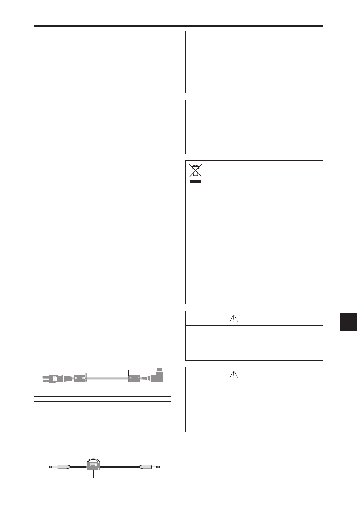
NOTE:
When you use the power cable (supplied), use the supplied
ferrite cores. Set the ferrite cores (supplied) on both ends
of the power cable (supplied), and then use the bands
(supplied) to fasten the ferrite cores (supplied) to the power
cable (supplied). If you do not this, this monitor will not
conform to mandatory FCC standards.
wer
supplie
n
WARNING
This product equipped with a three-wire grounding
(earthed) plug - a plug that has a third (grounding)
pin. This plug only fits a grounding-type power
outlet. If you are unable to insert the plug into an
outlet, contact a licensed electrician to replace the
outlet with a properly grounded one. Do not defeat
the safety purpose of the grounding plug.
Operating Environment
Operating environment temperature and humidity:
0 °C to +40 °C (+32 °F to +104 °F); less than 80
%RH (cooling vents not blocked)
Do not install this unit in a poorly ventilated area,
or in locations exposed to high humidity or direct
sunlight (or strong artificial light)
Disposing of your used
product
EU-wide legislation as implemented in
each Member State requires that used electrical
and electronic products carrying the mark (left)
must be disposed of separately from normal
household waste. This includes plasma monitors
and their electrical accessories. When you dispose
of such products, please follow the guidance of
your local authority and/or ask the shop where you
purchased the product.
After collecting the used products, they are reused
and recycled in a proper way. This effort will help
us reduce the wastes as well as the negative
impact to the human health and the environment
at the minimum level.
The mark on the electrical and electronic products
only applies to the current European Union
Member States.
CAUTION
When disposing of used batteries, please comply
with governmental regulations or environmental
public instruction’s rules that apply in your country/
area.
CAUTION
When changing batteries, use only conventional
non-rechageable alkaline or manganese batteries
NOTE:
When you use a remote cable (not supplied), use the
supplied ferrite core. Wind the remote cable (not supplied)
around the ferrite core (supplied) once, and then fasten
(2).
Risk of explosion if battery is replaced by an
incorrect type. Dispose of used batteries according
to the institutions.
the catch. If you do not this, this monitor will not conform
to mandatory FCC standards.
Remote cable (not supplied)
To plasma monitor
core
En-3

Contents
Important Information .................................. En-2
Contents ...................................................... En-4
Contents of the Package ........................................En-4
Options .............................................................. En-4
Installation .................................................. En-5
Ventilation Requirements for enclosure mounting ...... En-5
Creating a video wall ........................................... En-6
Cable Management.............................................. En-6
Caution when placing the plasma monitor in portrait mode .....
Using the remote control ....................................... En-7
Battery Installation and Replacement .......................... En-7
Using the wired remote control mode ......................... En-7
Operating Range ......................................................... En-7
En-7
Part Names and Function .............................. En-8
Front View .......................................................... En-8
Rear View/ Terminal Board ...................................En-9
Remote Control .................................................. En-12
Basic Operations ......................................... En-13
POWER ............................................................ En-13
To turn the unit ON and OFF: ................................... En-13
VOLUME .......................................................... En-13
To adjust the sound volume:...................................... En-13
MUTE ............................................................... En-13
To mute the audio: .................................................... En-13
DISPLAY ............................................................En-13
To check the settings: ................................................ En-13
DIGITAL ZOOM ................................................. En-13
AUTO ADJUST .................................................. En-13
To adjust the size or quality of the picture automatically: ...
OFF TIMER ........................................................En-13
To set the off timer: ................................................... En-13
To check the remaining time: .................................... En-13
To cancel the off timer: ............................................. En-13
En-13
WIDE Operations ......................................... En-14
Wide Screen Operation (manual) ........................ En-14
When viewing videos or digital video discs .............. En-14
Wide Screen Operation with Computer Signals ..... En-15
When “PICTURE SIZE” is set to “OFF” .................. En-15
SPLIT SCREEN Operations ............................. En-16
Showing a couple of pictures on the screen at the same time ..
Operations in the Side-by-side mode ......................... En-16
Operations in the Picture-in-picture mode ................. En-17
Selecting the input signals to be displayed ................ En-17
Zooming in on a specific input .................................. En-17
Adjusting the OSM controls ...................................... En-17
En-16
OSM (On Screen Menu) Controls ................... En-18
Menu Operations ...............................................En-18
Menu Tree ......................................................... En-19
Picture Settings Menu.......................................... En-21
Adjusting the picture ................................................. En-21
Setting the picture mode according to the brightness
of the room ............................................................. En-21
Reducing noise in the picture .................................... En-21
Setting the color temperature .................................... En-21
Adjusting the color to the desired level ..................... En-22
Changing the Gamma Curve ..................................... En-22
Making the Low Tone adjustments ........................... En-22
Adjusting the colors .................................................. En-22
Audio Settings Menu .......................................... En-23
Adjusting the treble, bass and left/right balance and
audio input select .................................................... En-23
Setting the allocation of the audio connectors ........... En-23
Image Adjust Settings Menu ................................ En-23
Adjusting the Position, Size, Fine Picture,
Picture Adj and Underscan ..................................... En-23
Option1 Settings Menu ....................................... En-24
Setting the on-screen menu ....................................... En-24
Setting the BNC input connector type ....................... En-24
Checking the signal being transmitted to RGB1 terminal ...
Setting a computer image to the correct RGB select screen ....
Setting high definition images to the suitable screen size ...
Setting the Input Skip ................................................ En-25
Resetting to the default values ................................... En-25
Option2 Settings Menu ....................................... En-26
Setting the power management for computer images ....
POWER/STANDBY indicator .................................. En-26
En-24
En-24
En-25
En-26
Setting the picture to suit the movie .......................... En-26
Reducing image retention ......................................... En-26
Setting the gray level for the sides of the screen ........ En-28
Setting the screen size for S1/S2 video input ............. En-29
Setting the picture size for RGB input signals ........... En-29
Setting the signal and black level for DVI signal ...... En-29
Setting the Protocol set ............................................. En-29
Setting CloseCaption ................................................ En-30
Setting the contrast of CloseCaption ......................... En-30
Option3 Settings Menu ....................................... En-30
Using the timer ......................................................... En-30
Setting the power on mode ........................................ En-32
Enabling/disabling the front panel controls ............... En-32
Enabling/disabling remote control wireless
transmission ........................................................... En-33
Loop Out setting ....................................................... En-33
REMOTE ID setting ................................................. En-33
ID number setting ..................................................... En-33
Video Wall setting ..................................................... En-34
Option4 Settings Menu ....................................... En-36
Removing the sub screen area when there is no input
signal detected for the sub picture .......................... En-36
Displaying the entire image during DIGITAL ZOOM
operations ............................................................... En-36
Displaying still images in the sub screen ................... En-36
Switching the input source quickly ........................... En-37
Displaying the information as a text .......................... En-37
Advanced OSM Settings Menu ............................ En-38
Setting the menu mode .............................................. En-38
Language Settings Menu ..................................... En-38
Setting the language for the menus ........................... En-38
Color System Settings Menu ................................ En-38
Setting the video signal format .................................. En-38
Source Information Menu ....................................En-38
Checking the frequencies, polarities of input signals, and
resolution ............................................................... En-38
External Control ......................................... En-39
Application ....................................................... En-39
Connections ...................................................... En-39
Type of connector: D-Sub 9-pin male ....................... En-39
Communication Parameters .................................En-39
External Control Codes (Reference) ...................... En-39
Pin Assignments ......................................... En-39
mini D-Sub 15-pin connector (Analog) ................. En-39
DVI-D 24-pin connector (Digital) ..........................En-39
1/8 Stereo Mini Jack (not supplied) for
REMOTE IN/OUT ...........................................En-40
Connection with STB .................................... En-40
Troubleshooting .......................................... En-41
Table of Signals Supported .......................... En-42
Specifications ............................................. En-46
Limited Warranty
Plasma Monitors ................. En-49
Contents of the Package
䡺 Plasma monitor (⳯1)
䡺 Power cord (⳯1, 3 m/9.8 feet)
䡺 Remote control (⳯1)
䡺 AAA Batteries (⳯2, Manganese battery for remote
control)
䡺 Manuals (Start up Guide and CD-ROM)
䡺 Ferrite cores for power cord (⳯2), bands for power
cord (⳯2)
䡺 Ferrite core for remote cable (⳯2)
䡺 Cable clampers (⳯3), beads bands (⳯3)
Options
• Wall mount unit
• Ceiling mount unit
• Tilt mount unit
• Tabletop Stand
• Attachable speakers
En-4
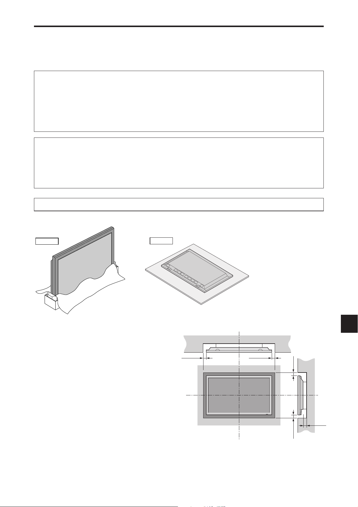
Installation
You can attach your optional mounts or stand to the plasma monitor in one of the following two ways:
* While it is upright. (See Drawing A)
* As it is laid down with the screen face down (See Drawing B). Lay the protective sheet, which was wrapped around the
monitor when it was packaged, beneath the screen surface so as not to scratch the screen face.
* Do not touch or hold the screen face when carrying the unit.
• This device cannot be installed on its own. Be sure to use a stand or original mounting unit. (Wall
mount unit, Stand, etc.)
• For correct installation and mounting it is strongly recommended to use a trained, authorized
dealer.
Failure to follow correct mounting procedures could result in damage to the equipment or injury
to the installer.
Product warranty does not cover damage caused by improper installation.
CAUTION
• Install the device following the installation manual of the optional accessory.
• Install the device in a stable and level environment that is strong enough to support the weight.
• Use the specified clasps for installing.
• After installation, take appropriate measures to prevent the plasma from tipping over or falling.
• Make sure to move or install the device with more than one person(s).
* Use only a mounting kit or stand recommended by the manufacturer and listed as an accessory.
Drawing A
Ventilation Requirements for
Drawing B
Wall
enclosure mounting
To allow heat to disperse, leave space between surrounding
objects as shown on the diagram when installing.
50 mm (2")
50 mm (2")
Wall
50 mm (2")
En-5
50 mm (2")
50 mm (2")

Creating a video wall
With built-in matrix display capability, you can create a (2⳯2, 3⳯3, 4⳯4, 5⳯5, 5⳯1, 1⳯5) video wall.
• Connect signal cables and remote cables as shown below.
Video signal RGB/DVD/HD signal
Remote
control
REMOTE
EXTERNAL CONTROL
)
IN OUT
RCA phono plug
1
(IN/OUT)
VIDEO Signal
AUDIO
VIDEO
2
R
3
L
(
MONO
IN
DVD
1
YCb/PbCr/Pr
)
Remote
control
IN
RGB signal/
DVD/HD signal
IN
BNC connector
RGB
2
/
DVD
2
/
HD
R/Cr/Pr G/Y B/Cb/Pb
2
RGB
1
AUDIO
3
RGB
VDHD
(IN/OUT)
(
)
Digital RGB
DVI
(
)
L
MONO
3
R
EXTERNAL CONTROL
REMOTE
IN OUT
RGB
2
/
DVD
2
/
HD
R/Cr/Pr G/Y B/Cb /Pb
2
RGB
1
AUDIO
3
RGB
3
R
VDHD
(IN/OUT)
(
Digital RGB
DVI
(
)
L
MONO
AUDIO
2
DVD
1
/
HD
1
AUDIO
1
VIDEO
2
R
1
(IN/OUT)
3
R
Y Cb/Pb Cr/Pr
L
(
(
MONO
)
)
MONO
L
AUDIO
2
1
/
HD
1
R
(
)
MONO
L
BNC connector
OUT
RGB signal/
DVD/HD signal
Remote
control
VIDEO Signal
OUT
Remote
control
OUT
Note:
1. The VIDEO1 and RGB1 terminals can be used for either INPUT or OUTPUT.
When LOOP OUT is ON, do not connect an OUTPUT signal from another unit as it may damage the other unit due to an
extraordinary load.
2. LOOP OUT can not be turned ON while signals are input to the RGB1 terminal.
3. LOOP OUT can be turned ON while signals are input to the RGB1 terminal if the POWER is switched ON.
Information
• To loop signals out to another plasma display, set the LOOP OUT to ON.
• To create a video wall, set the VIDEO WALL menu items properly.
• To connect monitors, please use a 1 m to 2 m (3.3 feet to 6.6 feet) BNC cable (any commercially available cable).
• If the image quality is poor, do not use the monitor’s out terminal. Use a distribution amplifier (any commercially
available distribution amplifier) to connect the split signals to the respective monitor INPUT terminals.
• Being used as a video wall function, maximaly 4-screen is rough-standard with lower than 1024⳯768, 60 Hz
signal.
• A distribution amplifier is particularly recommended when creating a 3⳯3 (or greater) video wall.
• When looping from plasma to plasma, a 1 m to 2 m (3.3 feet to 6.6 feet) 15 pin male D-Sub - 5BNC conversion
cable is required.
IN
OUT
Cable Management
Using the cable clampers and beads bands provided with the plasma display; Bundle the signal and audio cables at the
back of the unit to connect to the display.
42XM5 50XM6 60XM5
Back of the unit
mounting holes
To attach
Insert q into a mounting hole, then
snap w into the back of q to fix the
clamper.
Clampers are designed to be difficult
to undo once in place. Please attach
carefully. Cables can be routed to the
right or left.
Back of the unit
mounting holes
Bunch separated cables together and
secure them with the provided beads
bands.
Do not allow excessive stress to be
placed on the ends of cables.
To detach
Using pliers, twist the clamper 90° and
pull it outward. In some cases the
clamper may have deteriorated over
time and may get damaged when
removed.
Back of the unit
mounting holes
En-6
Caution when placing the plasma monitor in portrait mode
IN
OUT
REMOTE
EXTERNAL CONTROL
• Use the optional mount. Contact your store to purchase before installing.
• Rotate 90° clockwise as seen from the front when installing.
90°
• After installing, make sure the NEC logo is located at the
left hand side of the screen when facing the plasma from
the front.
• Be sure to set “OSM ANGLE” to “V” when using.
* Failure to heed the above cautions may lead to malfunction.
Using the remote control
INPUT SELECT
VOLUME
MENU/ENTER
Battery Installation and Replacement
Designated batteries:
Please use size AAA (R03) or AAA (LR03).
Insert the 2 “AAA” batteries, making sure to set them in
with the proper polarity.
1.Press and open the cover.
2.Align the batteries according to the and
indication inside the case.
DOWN UP LEFT/-RIGHT/+/EXIT
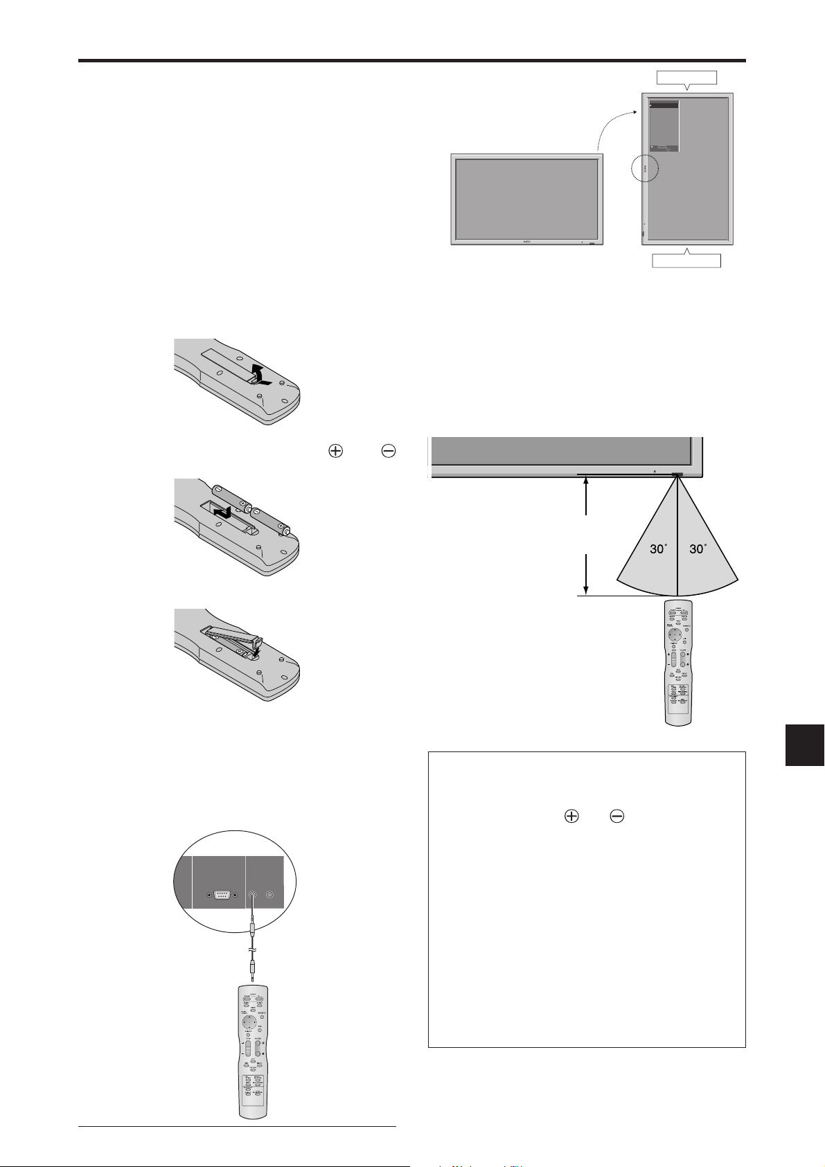
Operating Range
* Use the remote control within a distance of about 7 m/ 23
ft. from the front of the monitor’s remote control sensor
and at horizontal and vertical angles of up to approximately
30°.
* The remote control operation may not function if the
monitor’s remote control sensor is exposed to direct
sunlight or strong artificial light, or if there is an obstacle
between the sensor and the remote control.
OPTION1
MENU/ENTER
OSM
DOWN UP LEFT/
VOLUME
BNC INPUT
: RGB
-
RIGHT/
D-SUB INPUT
+
INPUT SELECT
/EXIT
: RGB
RGB SELECT
: AUTO
HD SELECT
: 1080B
INPUT SKIP
: OFF
ALL RESET
: OFF
1024ⴒ768
SEL.
MENU/ENTER
Bottom side
Top side
OK
EXIT
RETURN
3.Replace the cover.
Using the wired remote control mode
Connect the remote cable* to the remote control’s remote
jack and the “REMOTE IN” terminal on the monitor.
When the cable is connected, the mode automatically
switches to wired remote control. When the wired remote
control mode is used, the remote control can be operated
even if no batteries are loaded.
Remote Control
Cable*
To Remote Jack
Approx.
7 m/23 ft
CAUTION
• Use only the specified batteries.
• Make sure to insert the batteries correctly according
to the indications of and .
• Do not drop or mishandle the remote control.
• Do not get the remote control wet. If the remote
control gets wet, wipe it dry immediately.
• Avoid heat and humidity.
• When not using the remote control for a long period,
remove the batteries.
• Do not use new and old batteries together, or use
different types together.
• Do not take apart the batteries, heat them, or throw
them into a fire.
• When using the remote control in the wireless
condition, be sure to unplug the remote cable from
the REMOTE IN terminal on the monitor.
* The 1/8 Stereo Mini cable must be purchased separately.
En-7
Part Names and Function
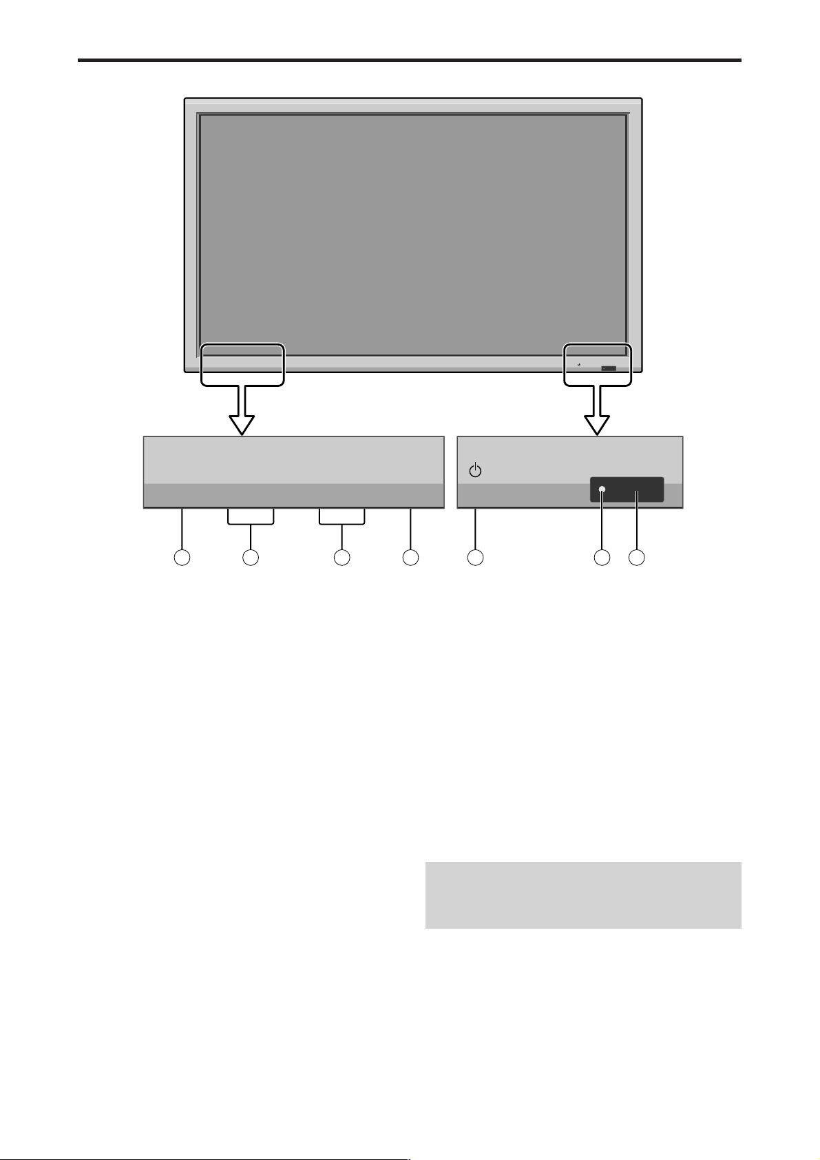
Front View
INPUT SELECT
VOLUME
MENU/ENTER
DOWN UP LEFT/-RIGHT/+/EXIT
MENU/ENTER
7
VOLUME
DOWN UP LEFT/-RIGHT/
6
5
q Power
Turns the monitor’s power on and off.
w Remote sensor window
Receives the signals from the remote control.
e POWER/STANDBY indicator
When the power is on ............................. Lights green.
When the power is in the standby mode ... Lights red.
r INPUT SELECT / EXIT
Switches the input.
Functions as the EXIT buttons in the On-Screen Menu
(OSM) mode.
INPUT SELECT
+
/EXIT
4
1
t LEFT/– and RIGHT/+
Functions as the CURSOR (
to adjust the picture parameters in the On-Screen Menu
(OSM) mode.
y VOLUME DOWN and UP
Adjusts the volume.
Functions as the CURSOR (▲/▼) buttons in the OnScreen Menu (OSM) mode.
u MENU/ENTER
Sets the On-Screen Menu (OSM) mode and displays
the main menu.
2
3
/ ) buttons and used
WARNING
The Power on/off switch does not completely
disconnect power from the display.
En-8
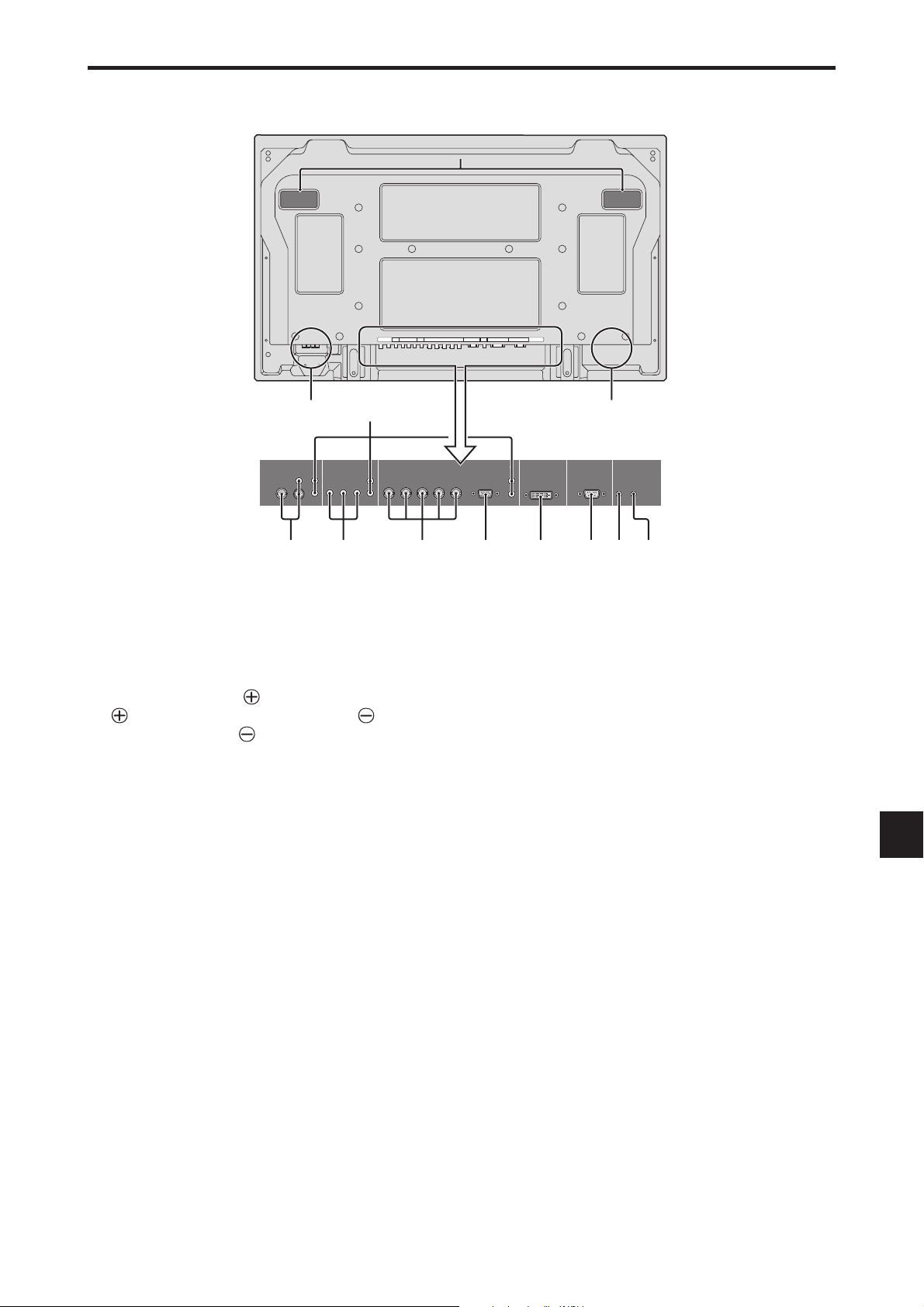
Rear View/ Terminal Board
42XM5
L
VIDEO
DVD
1
/ HD
1
RGB
2
/ DVD2 / HD
2
RGB
2
AUDIO
AUDIO
1
R/Cr/Pr G/Y B/ Cb/Pb
YL/R L/RCb/PbCr/Pr
1
AUDIO
3
RGB 3EXTERNAL CONTROL
(IN/OUT)
VD L/RHD
REMOTE
IN OUT
DVI
1
Y Cb/Pb Cr/Pr
)
D
AUDIO
2
DVD
1
/
HD
1
R
R/Cr/Pr G/Y B/C b/Pb
(
)
MONO
L
BA
AUDIO
VIDEO
2
(IN/OUT)
R
3
L
(
MONO
1
CE F GHIJK
A AC IN
Connect the included power cord here.
B EXT SPEAKER L and R
Connect speakers (optional) here. Maintain the correct
polarity. Connect the
EXT SPEAKER terminal and the (negative)
speaker wire to the
both LEFT and RIGHT channels.
Please refer to your speaker’s owner’s manual.
C VIDEO1, 2, 3 (BNC, RCA, S-Video)
Connect VCR’s, DVD’s or Video Cameras, etc. here.
VIDEO1 can be used for Input or Output.
D AUDIO1, AUDIO2, AUDIO3
These are audio input terminals.
The input is selectable. Set which video image
corresponds to the audio input from the audio menu
screen.
E DVD1 / HD1
Connect DVD’s, High Definition or Laser Discs, etc.
here.
(positive) speaker wire to the
EXT SPEAKER terminal on
RGB
2
/
DVD
2
/
HD
2
RGB
1
AUDIO
3
RGB
3
(IN/OUT)
R
(
)
Digital RGB
DVI
(
)
L
MONO
VDHD
EXTERNAL CONTROL
REMOTE
IN OUT
H RGB3 (DVI 24pin)
Connect a digital signal (TMDS) from a source with a
DVI output.
This input can be set for use with an RGB3.
I EXTERNAL CONTROL
This terminal is used when operating and controlling
the monitor externally with a control system (by RS232C).
J REMOTE IN
Connect the remote cable to the remote control’s
remote jack to obtain wired remote control.
K REMOTE OUT
Connect the remote cable to the REMOTE IN jack of
the other display monitor to obtain wired remote
control.
L Handles
Use when installing or carrying the plasma monitor.
F RGB2/ DVD2/ HD2
RGB2: You can connect an analog RGB signal
and the syncronization signal.
DVD2/ HD2: You can connect DVDs, High
Definition sources, Laser Discs, etc.
here.
This input can be set for use with an
RGB or component source.
G RGB1 (mini D-Sub 15pin)
Connect an analog RGB signal from a computer, etc.
here. This input can be used for Input or Output.
En-9
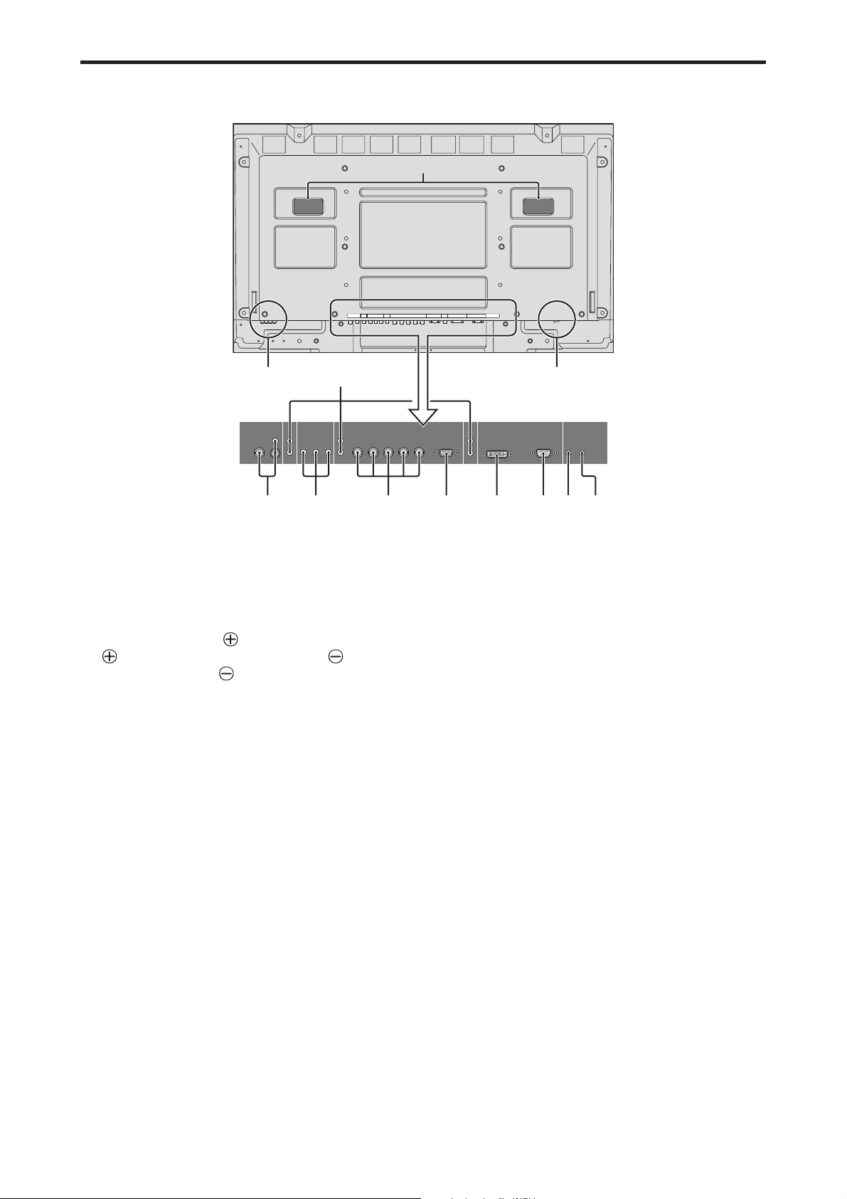
Rear View/ Terminal Board
50XM6
L
VIDEO
DVD
1
/
HD
1
RGB
2
/
DVD
2
/
HD2RGB
2
AUDIO
AUDIO
1
R/Cr/Pr G/Y B/ Cb/Pb
YL/R L/RCb/Pb Cr/Pr
1
AUDIO
3
RGB 3EXTERNAL CONTROL
(IN/OUT)
VD L/RHD
REMOTE
IN OUT
DVI
1
Y Cb/Pb Cr/Pr
)
D
AUDIO
2
DVD
1
/
HD
1
R
R/Cr/Pr G/Y B/C b/Pb
(
)
MONO
L
BA
AUDIO
VIDEO
2
(IN/OUT)
R
3
L
(
MONO
1
CE F GHIJK
A AC IN
Connect the included power cord here.
B EXT SPEAKER L and R
Connect speakers (optional) here. Maintain the correct
polarity. Connect the
EXT SPEAKER terminal and the (negative)
speaker wire to the
both LEFT and RIGHT channels.
Please refer to your speaker’s owner’s manual.
C VIDEO1, 2, 3 (BNC, RCA, S-Video)
Connect VCR’s, DVD’s or Video Cameras, etc. here.
VIDEO1 can be used for Input or Output.
D AUDIO1, AUDIO2, AUDIO3
These are audio input terminals.
The input is selectable. Set which video image
corresponds to the audio input from the audio menu
screen.
E DVD1 / HD1
Connect DVD’s, High Definition or Laser Discs, etc.
here.
(positive) speaker wire to the
EXT SPEAKER terminal on
RGB
2
/
DVD
2
/
HD
2
RGB
1
AUDIO
3
RGB
3
(IN/OUT)
R
(
)
Digital RGB
DVI
(
)
L
MONO
VDHD
EXTERNAL CONTROL
REMOTE
IN OUT
H RGB3 (DVI 24pin)
Connect a digital signal (TMDS) from a source with a
DVI output.
This input can be set for use with an RGB3.
I EXTERNAL CONTROL
This terminal is used when operating and controlling
the monitor externally with a control system (by RS232C).
J REMOTE IN
Connect the remote cable to the remote control’s
remote jack to obtain wired remote control.
K REMOTE OUT
Connect the remote cable to the REMOTE IN jack of
the other display monitor to obtain wired remote
control.
L Handles
Use when installing or carrying the plasma monitor.
F RGB2/ DVD2/ HD2
RGB2: You can connect an analog RGB signal
and the syncronization signal.
DVD2/ HD2: You can connect DVDs, High
Definition sources, Laser Discs, etc.
here.
This input can be set for use with an
RGB or component source.
G RGB1 (mini D-Sub 15pin)
Connect an analog RGB signal from a computer, etc.
here. This input can be used for Input or Output.
En-10
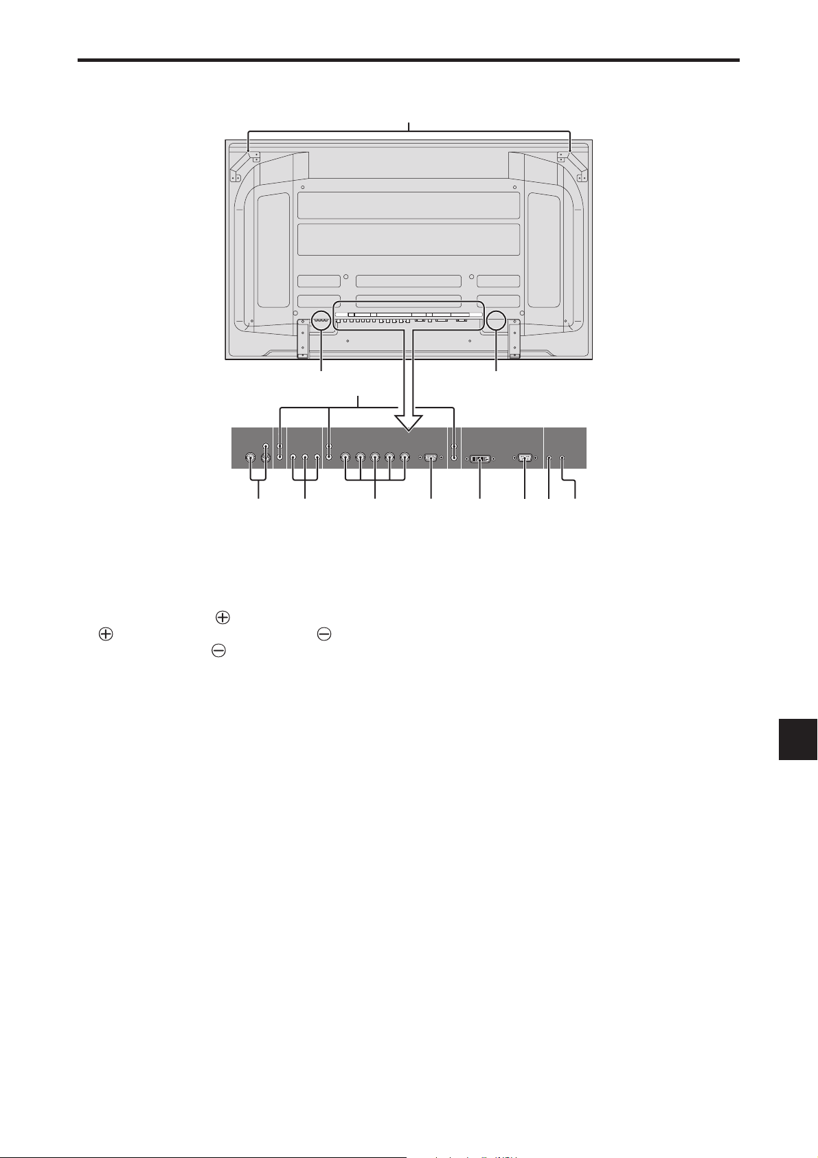
Rear View/ Terminal Board
60XM5
BA
DVD
1
/ HD
1
AUDIO
1
VIDEO
2
(IN/OUT)
R
Y Cb/Pb Cr/Pr
3
L
(
)
MONO
1
AUDIO
2
R
(
)
MONO
L
VIDEO
DVD
1
/ HD
1
AUDIO
1
YL/R L/RCb/Pb Cr/Pr
D
RGB
2
/ DVD2 / HD
R/Cr/Pr G/Y B/C b/Pb
L
AUDIO
RGB
2
/ DVD2 / HD
2
RGB
2
R/Cr/Pr G/Y B/ Cb/Pb
1
AUDIO
3
RGB 3EXTERNAL CONTROL
(IN/OUT)
VD L/RHD
2
RGB
VDHD
(IN/OUT)
REMOTE
IN OUT
DVI
1
AUDIO
3
RGB
3
R
(
)
DVI
Digital RGB
(
)
L
MONO
EXTERNAL CONTROL
REMOTE
IN OUT
CE F GHIJK
A AC IN
Connect the included power cord here.
B EXT SPEAKER L and R
Connect speakers (optional) here. Maintain the correct
polarity. Connect the
EXT SPEAKER terminal and the (negative)
speaker wire to the
both LEFT and RIGHT channels.
Please refer to your speaker’s owner’s manual.
C VIDEO1, 2, 3 (BNC, RCA, S-Video)
Connect VCR’s, DVD’s or Video Cameras, etc. here.
VIDEO1 can be used for Input or Output.
D AUDIO1, AUDIO2, AUDIO3
These are audio input terminals.
The input is selectable. Set which video image
corresponds to the audio input from the audio menu
screen.
E DVD1 / HD1
Connect DVD’s, High Definition or Laser Discs, etc.
here.
(positive) speaker wire to the
EXT SPEAKER terminal on
H RGB3 (DVI 24pin)
Connect a digital signal (TMDS) from a source with a
DVI output.
This input can be set for use with an RGB3.
I EXTERNAL CONTROL
This terminal is used when operating and controlling
the monitor externally with a control system (by RS232C).
J REMOTE IN
Connect the remote cable to the remote control’s
remote jack to obtain wired remote control.
K REMOTE OUT
Connect the remote cable to the REMOTE IN jack of
the other display monitor to obtain wired remote
control.
L Handles
Use when installing or carrying the plasma monitor.
F RGB2/ DVD2/ HD2
RGB2: You can connect an analog RGB signal
and the syncronization signal.
DVD2/ HD2: You can connect DVDs, High
Definition sources, Laser Discs, etc.
here.
This input can be set for use with an
RGB or component source.
G RGB1 (mini D-Sub 15pin)
Connect an analog RGB signal from a computer, etc.
here. This input can be used for Input or Output.
En-11
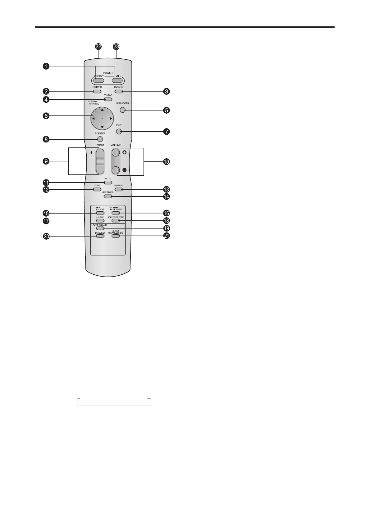
Remote Control
q POWER ON/STANDBY
Switches the power on/standby.
(This does not operate when the POWER/STANDBY
indicator of the plasma is off.)
w RGB/PC
Press this button to select RGB/PC as the source.
RGB/PC can also be selected using the INPUT
SELECT button on the monitor.
e DVD / HD
Press this button to select DVD/HD as the source.
DVD/HD can also be selected using the INPUT
SELECT button on the monitor.
r VIDEO
Press this button to select VIDEO as the source.
→ VIDEO1 → VIDEO2 → VIDEO3
VIDEO can also be selected using the INPUT SELECT
button on the monitor.
t MENU/ENTER
Press this button to access the OSM controls.
Press this button during the display of the main menu
to go to the sub menu.
y CURSOR (▲ / ▼ /
Use these buttons to select items or settings and to
adjust settings or switch the display patterns.
/ )
u EXIT
Press this button to exit the OSM controls in the main
menu. Press this button during the display of the sub
menu to return to the previous menu.
i POINTER
Press this button to display the pointer.
o ZOOM (+ /–)
Enlarges or reduces the image.
!0 VOLUME (+ /–)
Adjusts the audio volume.
!1 MUTE
Mutes the audio.
!2 WIDE
Press this button to select and switch the screen sizes.
WIDE button is not active for all signals.
!3 DISPLAY
Displays the source settings on the screen.
!4 OFF TIMER
Activates the off timer for the unit.
!5 SIDE BY SIDE
Press this button to show a couple of pictures in the
side-by-side mode.
!6 PICTURE IN PICTURE
Press this button to show a couple of pictures in the
picture-in-picture mode.
!7 SINGLE
Cancels the split screen mode.
!8 SELECT/FREEZE
Press this button to select the active picture in a split
screen mode.
When the PIC FREEZE function is operating, this button
can be used to display still images on the sub screen.
!9 AUTO ADJUST
Press this button to adjust Fine Picture, Picture ADJ,
Position, and Contrast automatically. Press this button
in video mode and the Auto Adjust switches to ZOOM
mode automatically when a letter box image is
displayed.
@0 ID SELECT
Set the ID number in the remote control. The remote
control can then be used only for a display with the
same ID number. When several displays are used
together they can be controlled individually.
@1 CLEAR/SEAMLESS SW
Clears the number set by the ID SELECT button.
When the SEAMLESS SW function is operating, this
button can be used to switch the input source quickly.
@2 Remote control signal transmitter
Transmits the remote control signals.
@3 Remote Jack
Insert the plug of the remote cable (The 1/8 Stereo
Mini cable) here when using the supplied remote
control in the wired condition.
En-12
Basic Operations
POWER
To turn the unit ON and OFF:
1. Plug the power cord into an active AC power outlet.
2. Press the Power button (on the unit).
The monitor’s POWER/STANDBY indicator turns red
and the standby mode is set.
3. Press the POWER ON button (on the remote control) to
turn on the unit.
The monitor’s POWER/STANDBY indicator will light
up (green) when the unit is on.
Press the POWER STANDBY button (on the remote control)
4.
or the Power button (on the unit) to turn off the unit.
The monitor’s POWER/STANDBY indicator turns red
and the standby mode is set (only when turning off the
unit with the remote control).
VOLUME
To adjust the sound volume:
1. Press and hold the VOLUME button (on the remote
control or the unit) to increase to the desired level.
2. Press and hold the VOLUME
control or the unit) to decrease to the desired level.
button (on the remote
MUTE
To mute the audio:
Press the MUTE button on the remote control to mute the
audio; press again to restore.
DISPLAY
To check the settings:
1. Press the DISPLAY button to display the display mode.
2. If the button is not pressed for approximately three seconds,
the menu turns off.
DIGITAL ZOOM
Digital zoom specifies the picture position and enlarges
the picture.
1. (Be sure ZOOM NAV is off.)
Press the POINTER button to display the pointer. (
To change the size of the picture:
Press the ZOOM+ button and enlarge the picture.
The pointer will change to resemble a magnifying glass.
)
(
A press of the ZOOM- button will reduce the picture
and return it to its original size.
To change the picture position:
Select the position with the ▲▼
2. Press the POINTER button to delete the pointer.
buttons.
)
AUTO ADJUST
To adjust the size or quality of the picture
automatically:
Press the AUTO ADJUST button.
OFF TIMER
To set the off timer:
The off timer can be set to turn the power off after 30, 60,
90 or 120 minutes.
1. Press the OFF TIMER button to start the timer at 30
minutes.
2. Press the OFF TIMER button to the desired time.
3. The timer starts when the menu turns off.
→ 30 → 60 → 90 → 120 → 0
OFF TIMER 30
To check the remaining time:
1. Once the off timer has been set, press the OFF TIMER
button once.
2. The remaining time is displayed, then turns off after a few
seconds.
3. When five minutes remain the remaining time appears
until it reaches zero.
OFF TIMER 28
To cancel the off timer:
1. Press the OFF TIMER button twice in a row.
2. The off timer is canceled.
OFF TIMER 0
Note:
After the power is turned off with the off timer ...
A slight current is still supplied to the monitor. When you
are leaving the room or do not plan to use the system for a
long period of time, turn off the power to the monitor.
Information
AUTO ADJUST ON setting
When RGB (still picture) input is selected:
Fine Picture, Picture ADJ, Position, and Contrast will
be adjusted automatically.
When RGB (motion picture), VIDEO, or Y/Pb/Pr
(component) input is selected:
The screen size switches to ZOOM mode automatically
when a letter box image is displayed.
En-13
WIDE Operations
Wide Screen Operation
With this function, you can select one of seven screen sizes.
(manual)
When viewing videos or digital video discs
1. Press the WIDE button on the remote control.
2. Within 3 seconds ...
Press the WIDE button again.
The screen size switches as follows:
→ NORMAL → FULL → STADIUM → ZOOM → 2.35:1 → 14:9 → UNDERSCAN
When a 720P or 1080I signal is input:
FULL ↔ 2.35:1
When displaying enhanced split screen:
NORMAL ↔ FULL
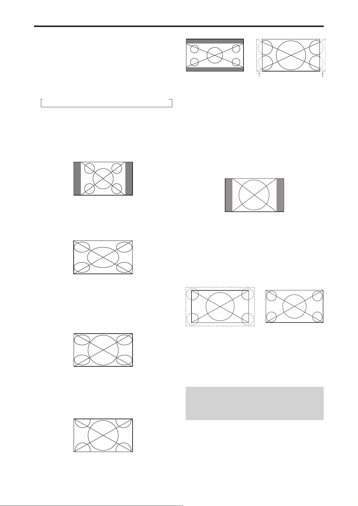
NORMAL size screen (4:3)
The normal size screen is displayed.
* The picture has the same size as video pictures with a 4 : 3
aspect ratio.
FULL size screen
2.35:1 size screen
Original image
Information is lost on both sides.
The squeezed film image is expanded to fulfill the entire
screen at a ratio of 2.35:1. Black bands do not appear at
the top and bottom but information is lost on the left and
right margins.
• This feature is available when the input signal is video,
component (480I, 480P, 576I, 576P, 720P, 1080I) or RGB
(525P or 625P signal from a scan converter).
* If black bands appear on the top and bottom in the full size
screen, select the 2.35:1 size screen to fill the screen and
avoid image retention.
14:9 size screen
The image is displayed at a 14:9 aspect ratio.
* This feature is available when the input signal is video,
component (480I, 480P, 576I, 576P) or RGB (525P or 625P
signal from a scan converter).
The image is expanded in the horizontal direction.
* Images compressed in the horizontal direction (“squeezed
images”) are expanded in the horizontal direction and
displayed on the entire screen with correct linearity.
(Normal images are expanded in the horizontal direction.)
STADIUM size screen
The picture is expanded in the horizontal and vertical
directions at different ratios.
* Use this for watching normal video programs (4:3) with a
wide screen.
ZOOM size screen
UNDERSCAN size screen
Set “UNDERSCAN” to “ON” in the “IMAGE ADJUST”.
Typical televisions crop the image (i.e., overscan). In order
to restore the entire image, select UNDERSCAN.
Overscan
* Picture noise or black border may appear near the edge of
screen depending on the connected component.
* The continuous display in this screen size over a prolonged
period of time may result in image retention.
* When Macrovision signal is input, the brightness may
change.
Note:
Do not allow 4:3 content to be displayed for extended
periods of time without using gray bars. This can cause
image retention.
Underscan
The picture is expanded in the horizontal and vertical
direction, maintaining the original proportions.
* Use this for theater size (wide) movies, etc.
En-14
Wide Screen Operation with
Computer Signals
Switch to the wide screen mode to expand the 4 : 3 image
to fill the entire screen.
1. Press the WIDE button on the remote control.
2. Within 3 seconds ...
Press the WIDE button again.
The screen size switches as follows:
→ NORMAL → FULL → ZOOM
When displaying enhanced split screen:
NORMAL ↔ FULL
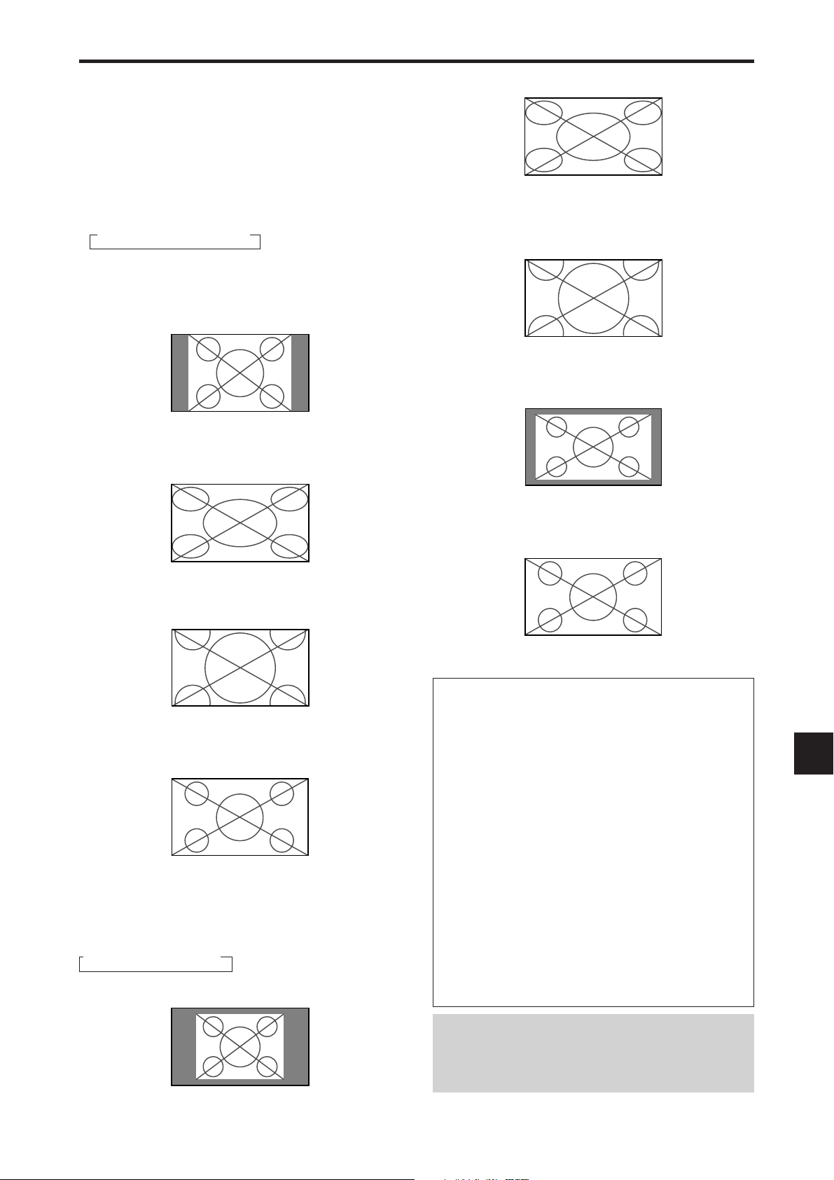
NORMAL size screen (4:3 or SXGA 5:4)
The picture has the same size as the normal computer image.
FULL size screen
FULL size screen
The image is expanded in the horizontal and vertical
direction.
ZOOM size screen
When wide signals are input.
TRUE
The image is expanded in the horizontal direction.
ZOOM size screen
When wide signals are input.
FULL size screen
When “PICTURE SIZE” is set to “OFF”
* This cannot be set in some models. “TRUE” size will not
be displayed in such cases.
The screen size switches as follows:
→ TRUE → FULL → ZOOM
TRUE size screen (VGA, SVGA 4:3)
The image is true resolution.
FULL
Information
Supported resolution
See page En-42 for details on the display output of the
various VESA signal standards supported by the
monitor.
“PICTURE SIZE” setting
When the setting of “PICTURE SIZE” is OFF, the size
of RGB-input pictures will be TRUE in place of
NORMAL.
When 852 (848) dot 480 line wide VGA*
signals with a vertical frequency of 60 Hz and
horizontal frequency of 31.7 (31.0) kHz are
input
Select an appropriate setting for RGB SELECT mode
referring to the“Table of Signals Supported” on page
En-42.
* “VGA”, “SVGA” and “SXGA” are registered
trademarks of IBM, Inc. of the United States.
The image is true resolution.
Note:
Do not allow 4:3 content to be displayed for extended
periods of time without using gray bars. This can cause
image retention.
En-15
VIDEO1 RGB1
AB
VIDEO1RGB1
BA
VIDEO1 RGB1
AB
VIDEO1 RGB1
AB
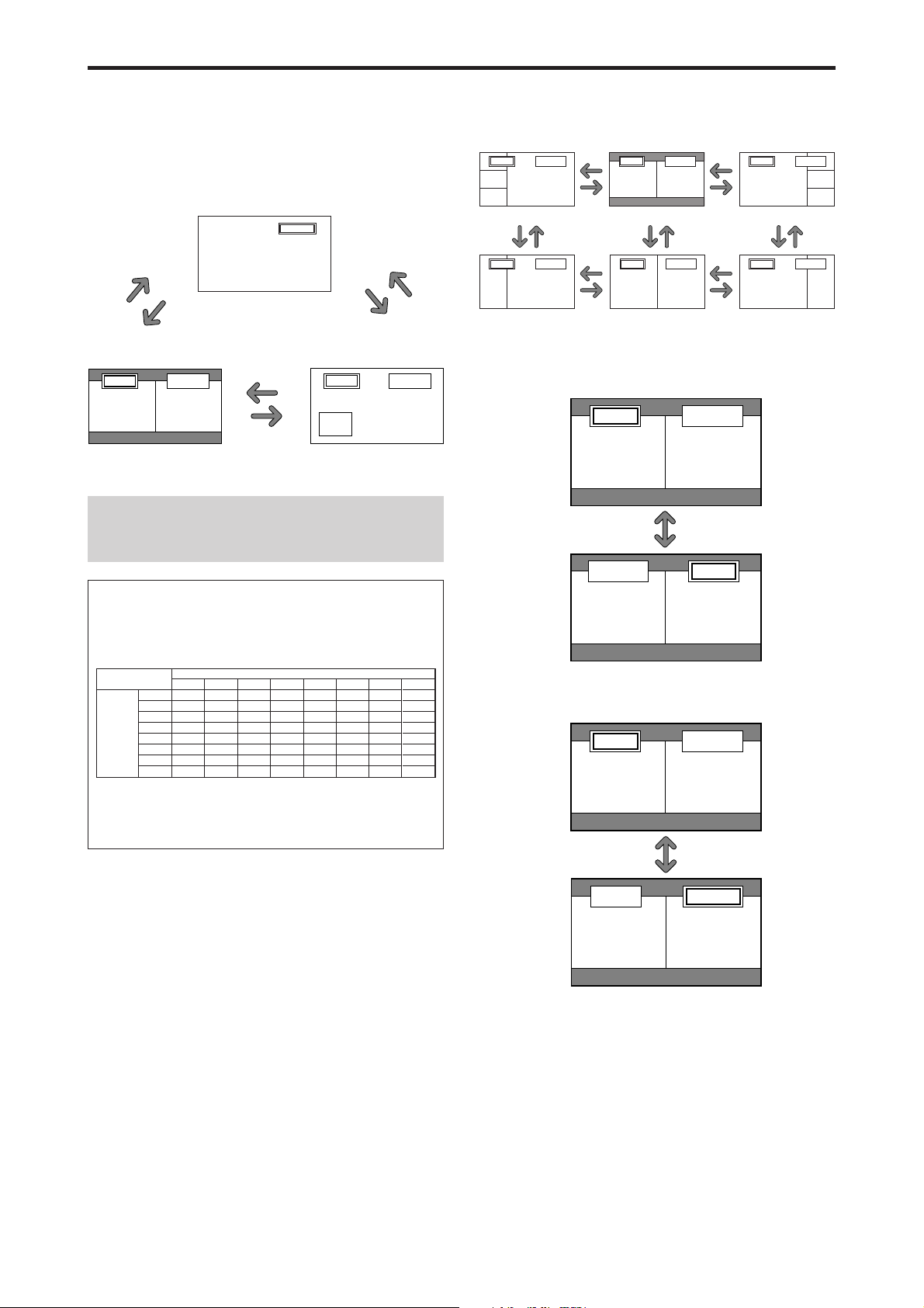
SPLIT SCREEN Operations
Showing a couple of pictures on the
screen at the same time
* There may be some RGB-input signals that may not be
displayed as not all signals are supported.
1. Press the button to select a screen mode from among single
mode, side-by-side, and picture-in-picture.
VIDEO1
SINGLE
button
SIDE BY SIDE
button
VIDEO1 RGB1
AB
A
PICTURE IN PICTURE
button
SIDE BY SIDE
button
PICTURE IN
PICTURE
button
VIDEO1
Sub
screen
Note:
Picture A and B on the above screen are not always of the
same height.
SINGLE
button
RGB1
Main screen
Operations in the Side-by-side mode
B
button
B
To change the picture size, press the cursor or
button.
VIDEO1 RGB2
A
B
Side-by-Side2-R
button
button
VIDEO1 RGB2
A
B
Side-by-Side4-R
button
button
VIDEO1 RGB2
AB
button
Side-by-Side1 Side-by-Side2-L
button
button
VIDEO1 RGB2
AB
button
Side-by-Side3 Side-by-Side4-L
button
button
button
button
button
VIDEO1 RGB2
A
button
VIDEO1 RGB2
A
To swap the picture on the right and the left, press the
cursor
button.
button
Information
Split screen operations may not function depending on
the combination of input signals. In the table below,
“” means Yes, “” means No.
Pictures displayed on the right/main screen (Select1)
VIDEO2
VIDEO3
DVD/HD1
DVD/HD2
RGB1
RGB2
RGB3
Pictures
displayed on
the left/sub
screen
(Select2)
VIDEO1
VIDEO2
VIDEO3
DVD/HD1
DVD/HD2
RGB1
RGB2
RGB3
VIDEO1
Split screen operations may not function
depending on the frequency of the RGB
signals.
To make the desired picture active, press the SELECT/
FREEZE button.
SELECT/FREEZE
button
En-16
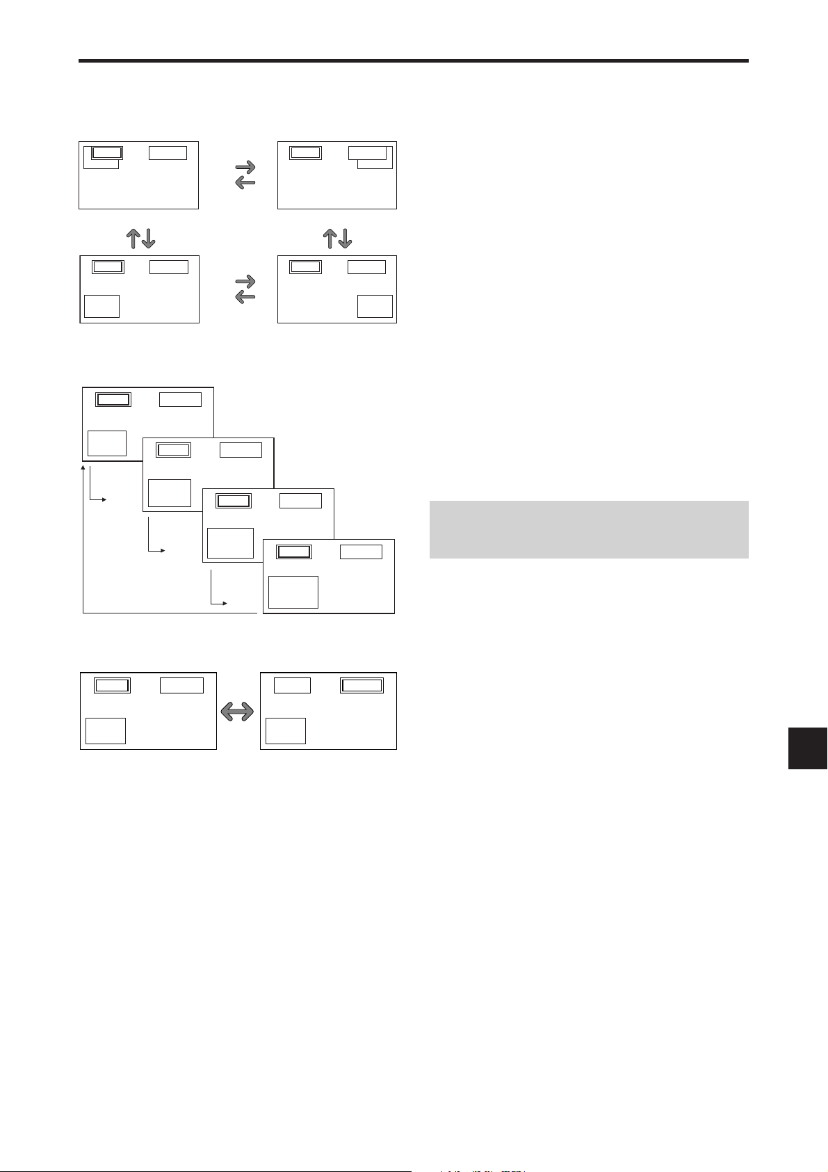
Operations in the Picture-in-picture mode
To move the position of the sub screen, press the cursor
or button.
VIDEO1
A
RGB2
B
Top Left
button
VIDEO1 RGB2
A
Bottom Left Bottom Right
B
button
button
button
button
button
VIDEO1
button
VIDEO1 RGB2
B
Top Right
B
RGB2
button
A
A
Selecting the input signals to be displayed
1. Press the SELECT/FREEZE button to make the desired
picture active.
2. Press the RGB/PC, VIDEO, or DVD/HD button.
Each press of the button changes the selection of the input
signal.
The INPUT SELECT button on the monitor can also be
used to change the selection.
Zooming in on a specific input
1. Press the SELECT/FREEZE button to make the desired
picture active.
2. Use the POINTER button and the ZOOM/ button to
enlage the picture.
For details, see “DIGITAL ZOOM” on page En-13.
To change the size of the sub screen, press the
VIDEO1 RGB1
button.
B
A
VIDEO1 RGB1
B
button
A
VIDEO1 RGB1
B
button
A
VIDEO1 RGB1
B
button
button
To make the desired picture active, press the SELECT/
FREEZE button.
VIDEO1 RGB1
B
A
SELECT/
FREEZE
button
A
VIDEO1 RGB1
B
A
Adjusting the OSM controls
1. Press the SELECT/FREEZE button to make the desired
picture active.
2. Press the MENU/ENTER button to display the MAIN
MENU.
3. Adjust the setting to your preference.
For details, see “OSM (On Screen Menu) Controls” on
page En-18.
Note:
During enhanced split screen, some functions of OSM
controls are not available.
En-17
OSM (On Screen Menu) Controls
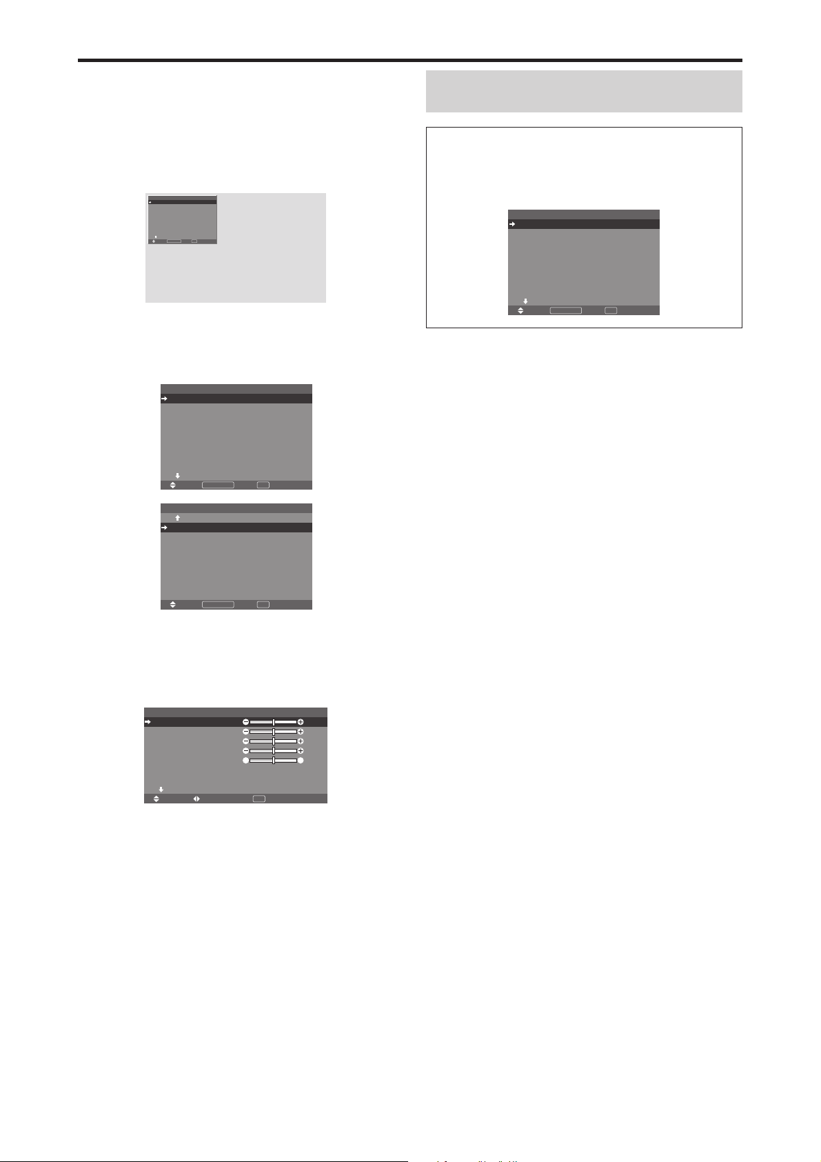
Menu Operations
The OSM window is displayed with respect to the
screen as shown on the diagram.
* Depending on the screen’s mode, the OSM may be
displayed differently.
In the explanation, the OSM section is shown close up.
MAIN MENU 1 / 2
PICTURE
AUDIO
IMAGE ADJUST
OPTION1
ADVANCED OSM
: OFF
NEXT PAGE
MENU/ENTEROKEXIT
SEL.
The following describes how to use the menus and the
selected items.
1. Press the MENU/ENTER button on the remote control to
display the MAIN MENU.
EXIT
MAIN MENU 1 / 2
PICTURE
AUDIO
IMAGE ADJUST
OPTION1
ADVANCED OSM
NEXT PAGE
MENU/ENTEROKEXIT
SEL.
MAIN MENU 2 / 2
PREVIOUS PAGE
LANGUAGE
COLOR SYSTEM
SOURCE INFORMATION
: OFF
EXIT
Note:
The main menu disappears by pressing the EXIT
button.
Information
Advanced menu mode
When “ADVANCED OSM” is set to “ON” in the main
menu (1/2), full menu items will be shown.
MAIN MENU 1 / 2
PICTURE
AUDIO
IMAGE ADJUST
OPTION1
OPTION2
OPTION3
OPTION4
ADVANCED OSM
NEXT PAGE
MENU/ENTEROKEXIT
SEL.
: ON
EXIT
* The actual screen may be different from the ones in
this manual.
MENU/ENTEROKEXIT
SEL.
EXIT
2. Press the cursor buttons ▲ ▼ on the remote control to
highlight the menu you wish to enter.
3. Press the MENU/ENTER button on the remote control to
select a sub menu or item.
CONTRAST
BRIGHTNESS
SHARPNESS
COLOR
TINT
PICTURE MODE
NR
NEXT PAGE
SEL. ADJ. RETURN
PICTURE 1 / 2
: NORMAL
: OFF
EXIT
: 52
: 32
: 16
: 32
GR
: 32
4. Adjust the level or change the setting of the selected item
by using the cursor buttons
on the remote control.
5. The adjustments or settings are then stored in memory.
The change is stored until another change is made.
6. Repeat steps 2 – 5 to adjust an additional item, or press
the EXIT button on the remote control to return to the
main menu.
* When adjusting using the bar at the bottom of the screen,
press the
or button within 5 seconds. If not, the
current setting is stored and the previous screen appears.
En-18
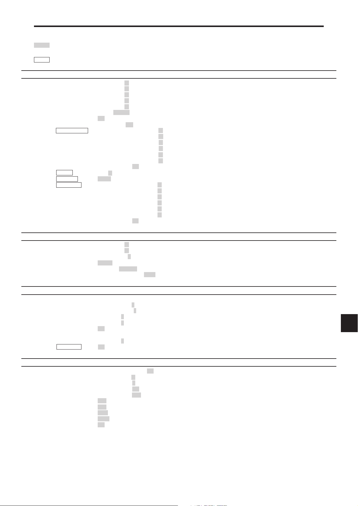
Menu Tree
:Shaded areas indicate the default value.
←→
: Press the
:Menu items in a ruled box are available when the ADVANCED OSM is set to ON.
Main menu Sub menu Sub menu 2 Sub menu 3 Sub menu 4 RESET OSM ANGLE “V” REFERENCE
PICTURE CONTRAST ←→ 0←52→72 YES YES En-21
BRIGHTNESS ←→ 0←32→64 YES YES En-21
SHARPNESS ←→ 0←16→32 YES YES En-21
COLOR ←→ 0←32→64 YES YES En-21
TINT R←→G 0←32→64 YES YES En-21
PICTURE MODE BRIGHT/NORMAL/THEAT.1/THEAT.2/DEFAULT YES YES En-21
NR OFF/NR-1/NR-2/NR-3 YES YES En-21
COLOR TEMP. LOW/MID LOW/MID/HIGH YES YES En-21
WHITE BALANCE GAIN RED ←→ 0←40→70 YES NO En-22
GAMMA 1←→2←…→4 YES NO En-22
LOW TONE *
COLOR TUNE RED Y←→M0←32→64 YES NO En-22
or button to adjust.
GAIN GREEN ←→ 0←40→70 YES NO En-22
GAIN BLUE ←→ 0←40→70 YES NO En-22
BIAS RED ←→ 0←40→70 YES NO En-22
BIAS GREEN ←→ 0←40→70 YES NO En-22
BIAS BLUE ←→ 0←40→70 YES NO En-22
RESET OFF←→ON YES NO En-22
4
MODE1←→MODE2 YES NO En-22
GREEN C←→Y0←32→64 YES NO En-22
BLUE M←→C0←32→64 YES NO En-22
YELLOW G←→R0←32→64 YES NO En-22
MAGENTA R←→B0←32→64 YES NO En-22
CYAN B←→G0←32→64 YES NO En-22
RESET OFF←→ON YES NO En-22
Main menu Sub menu Sub menu 2 Sub menu 3 Sub menu 4 RESET OSM ANGLE “V” REFERENCE
AUDIO BASS ←→ 0←13→26 YES YES En-23
TREBLE ←→ 0←13→26 YES YES En-23
BALANCE L←→R -22←0→+22 YES YES En-23
AUDIO INPUT1 VIDEO 1-3 / DVD/HD 1-2 / RGB 1-3 YES YES En-23
AUDIO INPUT2 VIDEO 1-3 / DVD/HD 1-2 / RGB 1-3 YES YES En-23
AUDIO INPUT3 VIDEO 1-3 / DVD/HD 1-2 / RGB 1-3 YES YES En-23
Main menu Sub menu Sub menu 2 Sub menu 3 Sub menu 4 RESET OSM ANGLE “V” REFERENCE
IMAGE ADJUST ASPECT MODE NORMAL/FULL/STADIUM/ZOOM/2.35:1/14:9/UNDERSCAN/TRUE*
Main menu Sub menu Sub menu 2 Sub menu 3 Sub menu 4 RESET OSM ANGLE “V” REFERENCE
OPTION1 OSM DISPLAY OSM OFF←→ON YES YES En-24
V-POSITION ←→ -64←0→+64 YES YES En-23
H-POSITION ←→ -128←0→+127 YES YES En-23
V-HEIGHT ←→ 0←→64 YES YES En-23
H-WIDTH ←→ 0←→64 YES YES En-23
AUTO PICTURE OFF←→ON*
FINE PICTURE*
PICTURE ADJ.*
UNDERSCAN OFF←→ON YES NO En-23
BNC INPUT RGB←→COMP. YES YES En-24
D-SUB INPUT RGB — YES En-24
RGB SELECT AUTO YES YES En-24
HD SELECT 1080B/1035I/1080A NO YES En-25
INPUT SKIP OFF←→ON YES YES En-25
ALL RESET OFF←→ON — YES En-25
1
←→*20←→64 YES YES En-23
1
←→*20←→64 YES YES En-23
OSM ADJ. 1←…→6 YES YES En-24
OSM ANGLE H←→V YES YES En-24
OSM ORBITER OFF←→ON YES YES En-24
OSM CONTRAST LOW←→NORMAL YES YES En-24
2
3
— YES En-23
NO YES En-23
En-19
Main menu Sub menu Sub menu 2 Sub menu 3 Sub menu 4 RESET OSM ANGLE “V” REFERENCE
OPTION2 PWR. MGT. OFF←→ON YES NO En-26
CINEMA MODE OFF←→ON YES NO En-26
LONG LIFE PLE AUTO/LOCK 1/LOCK 2/LOCK 3 YES NO En-26
ORBITER AUTO 1 YES NO En-27
INVERSE OFF YES NO En-27
SCREEN WIPER OFF YES NO En-28
SOFT FOCUS OFF/1/2/3/4 YES NO En-28
GRAY LEVEL 0←…→3←…→15 YES NO En-28
S1/S2 AUTO←→OFF YES NO En-29
PICTURE SIZE*
DVI SET UP PLUG/PLAY PC←→STB/DVD NO NO En-29
PROTOCOL SET OFF←→ON YES NO En-29
CLOSECAPTION OFF←→CC1~4←→TEXT1~4 YES NO En-30
CAPTION CONT LOW←→NORMAL YES NO En-30
Main menu Sub menu Sub menu 2 Sub menu 3 Sub menu 4 RESET OSM ANGLE “V” REFERENCE
OPTION3 TIMER PRESENT TIME
PWR. ON MODE INPUT LAST /MULTI/ VIDEO 1-3 / DVD/HD 1-2 / RGB 1-3 YES NO En-32
CONTROL LOCK OFF←→ON YES NO En-32
IR REMOTE OFF←→ON YES NO En-33
LOOP OUT OFF←→ON YES NO En-33
REMOTE ID ALL←→1←…→4 NO NO En-33
ID NUMBER ALL←→1←…→256 YES NO En-33
VIDEO WALL DIVIDER OFF/1/22/33/44/55/51/15 YES NO En-34
Main menu Sub menu Sub menu 2 Sub menu 3 Sub menu 4 RESET OSM ANGLE “V” REFERENCE
OPTION4 SUB. PICTURE SUB. P DETECT OFF←→AUTO YES NO En-36
ZOOM NAV OFF←→S BY S←→BTM LFT←→BTM RGT←→TOP RGT←→TOP LFT YES NO En-36
PIC FREEZE OFF←→S BY S1←→S BY S2←→BTM LFT←→BTM RGT←→TOP RGT←→TOP LFT YES NO En-36
SEAMLESS SW OFF YES NO En-37
TEXT INSERT OFF/BOTTOM-1/BOTTOM-2/BOTTOM-3/MID. LOW/MID. HIGH/TOP-3/TOP-2/TOP-1/LEFT/RIGHT YES NO En-37
Main menu Sub menu Sub menu 2 Sub menu 3 Sub menu 4 RESET OSM ANGLE “V” REFERENCE
ADVANCED OSM OFF←→ON YES NO En-38
LANGUAGE ENGLISH/DEUTSCH/FRANÇAIS/ESPAÑOL/ITALIANO/SVENSKA/У/PORTUGUÊS NO NO En-38
COLOR SYSTEM AUTO/3.58 NTSC/4.43 NTSC/PAL/PAL 60/PAL-N/PAL-M/SECAM NO YES En-38
SOURCE INFORMATION
— — YES En-38
3
OFF←→ON YES NO En-29
BLACK LEVEL LOW←→HIGH NO NO En-29
TIMER OFF YES NO En-31
VOLUME LAST←→0←…→42 YES NO En-32
POSITION
DISP. MODE SPLIT←→BLANK YES NO En-34
AUTO ID OFF←→ON YES NO En-34
IMAGE ADJUST ASPECT MODE
P. ON DELAY OFF/ON/MODE1/MODE2 YES NO En-35
PLE LINK OFF←→ON YES NO En-35
SUB. P RATE 20%←…→100% YES NO En-36
DISPLAY FADE←→NORMAL YES NO En-36
ON SELECT1/SELECT2 YES NO En-37
AUTO 2 YES NO En-27
MANUAL H-DOT/V-LINE/TIME YES NO En-27
OFF YES NO En-27
ON WORKING TIME/WAITING TIME YES NO En-27
WHITE YES NO En-27
ON WORKING TIME/WAITING TIME/SPEED YES NO En-28
DAYLIGHT SAVING TIME
DAY/HOUR/MINUTES NO NO En-30
PROGRAM DAY/ON/OFF(HOUR, MINUTES)/INPUT/FUNC. YES NO En-31
REPEAT SINGLE/MULTI/VIDEO-W YES NO En-31
No.1←…→No.4/No.7←…→No.15/No.16←…→No.31/No.32←…→No.56
V-POSITION/H-POSITION/V-HEIGHT/H-WIDTH/AUTO PICTURE/
FINE PICTURE*
INPUT/SUB. P DETECT/PIC. RATE/DISPLAY YES NO En-37
OFF←→ON NO NO En-30
— NO En-34
NORMAL/FULL/STADIUM/ZOOM/2.35:1/14:9/UNDERSCAN/TRUE
1
/PICTURE ADJ.*1/UNDERSCAN
*3— NO En-35
*1 Only when AUTO PICTURE is OFF.
*2 RGB only.
*3 “PICTURE SIZE” and “TRUE” are only for 50 and 60 inch types.
*4 “LOW TONE” is only for 50 inch type.
Information
Restoring the factory default settings
Select “ALL RESET” under the OPTION1 menu. Note that this also restores other settings to the factory defaults.
En-20
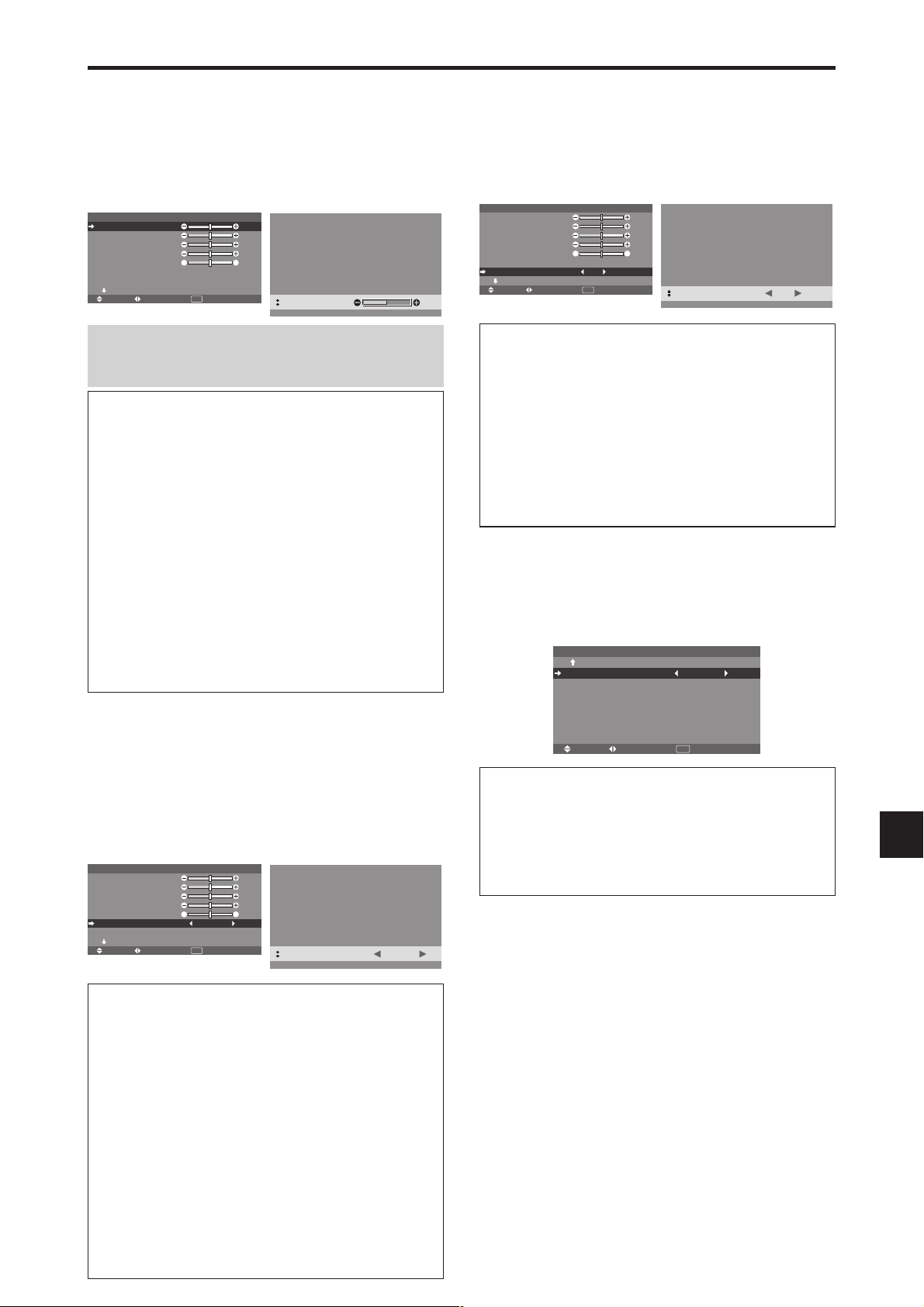
Picture Settings Menu
Adjusting the picture
The contrast, brightness, sharpness, color and tint can be
adjusted as desired.
Example: Adjusting the contrast
On “CONTRAST” of “PICTURE” menu, adjust the contrast.
CONTRAST
BRIGHTNESS
SHARPNESS
COLOR
TINT
PICTURE MODE
NR
NEXT PAGE
SEL. ADJ. RETURN
PICTURE 1 / 2
: NORMAL
: OFF
EXIT
: 52
: 32
: 16
: 32
GR
: 32
CONTRAST
:
52
Reducing noise in the picture
Use these settings if the picture has noise due to poor
reception or when playing video tapes on which the picture
quality is poor.
Example: Setting “NR-3”
On “NR” of “PICTURE” menu, select “NR-3”.
CONTRAST
BRIGHTNESS
SHARPNESS
COLOR
TINT
PICTURE MODE
NR
NEXT PAGE
SEL. ADJ. RETURN
PICTURE 1 / 2
: NORMAL
: OFF
EXIT
: 52
: 32
: 16
: 32
GR
: 32
NR
:
NR-3
Note:
If “CAN NOT ADJUST” appears ...
When trying to enter the PICTURE submenu, make sure
PICTURE MODE is not set to DEFAULT.
Information
Picture adjustment screen
CONTRAST: Changes the picture’s white level.
BRIGHTNESS:
Changes the picture’s black level.
SHARPNESS: Changes the picture’s sharpness.
Adjusts picture detail of VIDEO display.
COLOR: Changes the color density.
TINT: Changes the picture’s tint. Adjust for natural
colored skin, background, etc.
Adjusting the computer image
Only the contrast and brightness can be adjusted when
a computer signal is connected.
Restoring the factory default settings
Select “DEFAULT” under the “PICTURE MODE”
settings.
Setting the picture mode according to the
brightness of the room
There are four picture modes that can be used effectively
according to the environment in which you are viewing
the display.
Example: Setting the “THEAT. 1” mode
On “PICTURE MODE” of “PICTURE” menu, select
“THEAT. 1”.
CONTRAST
BRIGHTNESS
SHARPNESS
COLOR
TINT
PICTURE MODE
NR
NEXT PAGE
SEL. ADJ. RETURN
PICTURE 1 / 2
: NORMAL
: OFF
EXIT
: 52
: 32
: 16
: 32
GR
: 32
PICTURE MODE
:
THEAT. 1
Information
NR
* “NR” stands for Noise Reduction.
* This function reduces noise in the picture.
Types of noise reduction
There are three types of noise reduction. Each has a
different level of noise reduction.
The effect becomes stronger as the number increases
(in the order NR-1 → NR-2 → NR-3).
OFF: Turns the noise reduction function off.
Setting the color temperature
Use this procedure to set color tone produced by the plasma
display.
Example: Setting “HIGH”
On “COLOR TEMP.” of “PICTURE” menu, select “HIGH”.
PREVIOUS PAGE
COLOR TEMP.
GAMMA
LOW TONE
COLOR TUNE
SEL. ADJ. RETURN
PICTURE 2 / 2
: HIGH
: 2
: MODE1
EXIT
Information
Setting the color temperature
LOW: More red
MID LOW: Slightly red
MID: Standard (slightly bluer)
HIGH: More blue
Information
Types of picture modes
THEAT. 1, 2: Set this mode when watching video in a
dark room.
This mode provides darker, finer pictures, like the
screen in movie theaters.
For a darker image, select THEAT. 2.
NORMAL: Set this mode when watching video in a bright
room.
BRIGHT: This mode provides brighter pictures than
NORMAL.
This mode provides dynamic pictures with distinct
differences between light and dark sections.
DEFAULT: Use this to reset the picture to the factory
default settings.
En-21
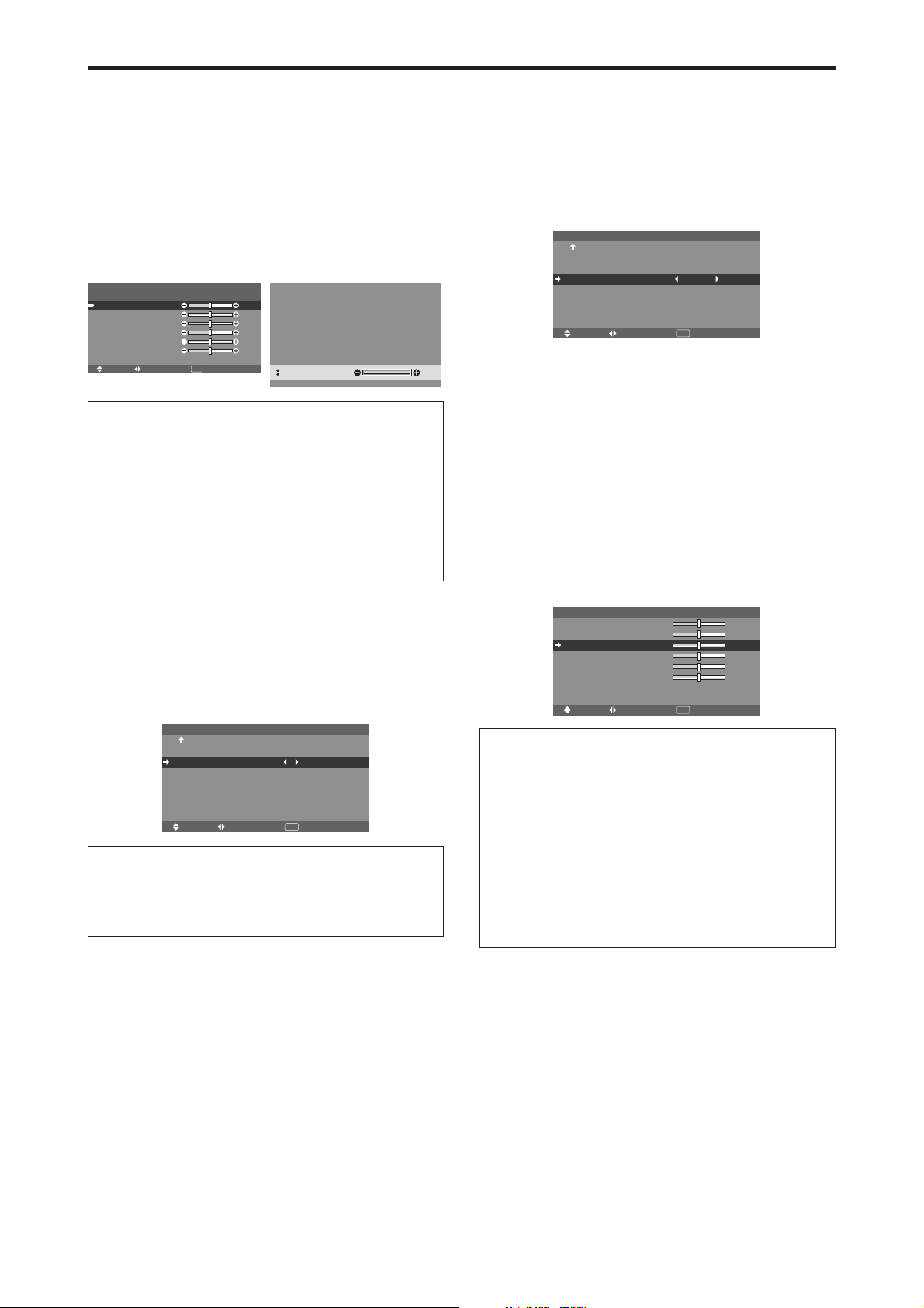
Adjusting the color to the desired level
Use this procedure to adjust the white balance for each
color temperature to achieve the desired color quality.
Example: Adjusting the “GAIN RED” of “HIGH” color
temperature
Set “ADVANCED OSM” to “ON” in the MAIN MENU.
On “COLOR TEMP.” of “PICTURE” menu, select “HIGH”,
then press the MENU/ENTER button.
The “WHITE BALANCE” screen appears.
On “GAIN RED”, adjust the white balance.
WHITE BALANCE
COLOR TEMP. HIGH
GAIN RED
GAIN GREEN
GAIN BLUE
BIAS RED
BIAS GREEN
BIAS BLUE
RESET
SEL. ADJ. RETURN
: OFF
EXIT
: 40
: 40
: 40
: 40
: 40
: 40
GAIN RED
:
70
Information
Adjusting the white balance
GAIN R/G/B: White balance adjustment for white level.
BIAS R/G/B: White balance adjustment for black level.
RESET: Resets settings to the factory default values.
Use
and buttons to select “ON”, then press the
MENU/ENTER button.
Restoring the factory default settings
Select “RESET” under the WHITE BALANCE menu.
Changing the Gamma Curve
This feature adjusts the brightness of the midtone areas
while keeping shadows and highlights unchanged.
Example: Setting “3”
Set “ADVANCED OSM” to “ON” in the MAIN MENU.
On “GAMMA” of “PICTURE” menu, select “3”.
PREVIOUS PAGE
COLOR TEMP.
GAMMA
LOW TONE
COLOR TUNE
SEL. ADJ. RETURN
PICTURE 2 / 2
: MID
: 3
: MODE1
EXIT
Information
GAMMA settings
The picture becomes darker as the number increases
(in the sequence of 1, 2, 3, 4).
Making the Low Tone adjustments
You can select the tone reproduction from 2 modes.
This function is effective especially for dark images.
* This function is available only for 50 inch type.
Example: Setting “MODE2”
Set “ADVANCED OSM” to “ON” in the MAIN MENU.
On “LOW TONE” of “PICTURE” menu, select “MODE2”.
PREVIOUS PAGE
COLOR TEMP.
GAMMA
LOW TONE
COLOR TUNE
SEL. ADJ. RETURN
PICTURE 2 / 2
: MID
: 2
: MODE2
EXIT
Adjusting the colors
Use this procedure to adjust hue and color density for red,
green, blue, yellow, magenta and cyan without changing
the white point.
You can accentuate the green color of trees, the blue of
the sky, etc.
Example: Adjusting the color tune for blue
Set “ADVANCED OSM” to “ON” in the MAIN MENU.
On “PICTURE” menu, select “COLOR TUNE”, then press
the MENU/ENTER button.
The “COLOR TUNE” screen appears.
On “BLUE” of “COLOR TUNE”, adjust the color tune.
RED
GREEN
BLUE
YELLOW
MAGENTA
CYAN
RESET
SEL. ADJ. RETURN
COLOR TUNE
: OFF
EXIT
MY
: 32
YC
: 32
CM
: 32
RG
: 32
BR
: 32
GB
: 32
Information
COLOR TUNE settings
RED: Adjusts hue of Red
GREEN: Adjusts hue of Green
BLUE: Adjusts hue of Blue
YELLOW: Adjusts hue of Yellow
MAGENTA: Adjusts hue of Magenta
CYAN: Adjusts hue of Cyan
RESET: Resets settings to the factory default value.
and buttons to select “ON”, then press the
Use
MENU/ENTER button.
En-22

Audio Settings Menu
Adjusting the treble, bass and left/right
balance and audio input select
The treble, bass and left/right balance can be adjusted to
suit your tastes.
Example: Adjusting the bass
On “BASS” of “AUDIO” menu, adjust the bass.
Note :
BASS
TREBLE
BALANCE
AUDIO INPUT1
AUDIO INPUT2
AUDIO INPUT3
SEL. ADJ. RETURN
AUDIO
: VIDEO1
: DVD/HD1
: RGB1
EXIT
If “CAN NOT ADJUST” appears...
: 26
: 13
RL
: ±0
Set “AUDIO INPUT” on the AUDIO menu correctly.
Information
Audio settings menu
BASS: Controls the level of low frequency sound.
TREBLE: Controls the level of high frequency sound.
BALANCE: Controls the balance of the left and right
channels.
Setting the allocation of the audio connectors
Setting the AUDIO 1, 2, and 3 connectors to the desired
input.
Example: Setting “AUDIO INPUT1” to “VIDEO2”
On “AUDIO INPUT1” of “AUDIO” menu, select
“VIDEO2”.
The available sources depend on the settings of input.
BASS
TREBLE
BALANCE
AUDIO INPUT1
AUDIO INPUT2
AUDIO INPUT3
SEL. ADJ. RETURN
AUDIO
: VIDEO2
: DVD/HD1
: RGB1
EXIT
: 13
: 13
RL
: ±0
Information
AUDIO INPUT
A single audio input cannot be selected as the audio
channel for more than one input terminal.
Image Adjust Settings Menu
Adjusting the Position, Size, Fine Picture,
Picture Adj and Underscan
The position of the image can be adjusted and flickering
of the image can be corrected.
Example: Adjusting the vertical position in the normal
mode
On “V-POSITION” of “IMAGE ADJUST” menu, adjust the
position.
The mode switches as follows each time the
pressed:
NORMAL ↔ FULL
* The mode can also be switched by pressing the WIDE
button on the remote control.
* The settings on the IMAGE ADJUST menu are not preset
at the factory.
or button is
ASPECT MODE
V-POSITION
H-POSITION
V-HEIGHT
H-WIDTH
AUTO PICTURE
FINE PICTURE
PICTURE ADJ.
UNDERSCAN
IMAGE ADJUST
: NORMAL
: OFF
: OFF
SEL. ADJ. RETURN
EXIT
: ±0
: ±0
: 0
: 0
: 0
: 0
V-POSITION
Information
When “AUTO PICTURE” is “OFF”
ASPECT MODE
V-POSITION
H-POSITION
V-HEIGHT
H-WIDTH
AUTO PICTURE
FINE PICTURE
PICTURE ADJ.
UNDERSCAN
SEL. ADJ. RETURN
IMAGE ADJUST
: FULL
: OFF
: OFF
EXIT
: ±0
: ±0
: 32
: 32
: 32
: 32
When Auto Picture is off, the Fine Picture and the
Picture ADJ. items are displayed so that you can adjust
them.
Adjusting the Auto Picture
ON: The Picture ADJ., Fine Picture and Position
adjustments are made automatically.
Not available for digital ZOOM.
OFF: The Picture ADJ., Fine Picture and Position
adjustments are made manually.
* If FINE PICTURE can’t be adjusted, set Auto Picture
to OFF and adjust manually.
Adjusting the position of the image
V-POSITION: Adjusts the vertical position of the
image.
H-POSITION: Adjusts the horizontal position of the
image.
V-HEIGHT: Adjusts the vertical size of the image.
(Not available for STADIUM mode)
H-WIDTH: Adjusts the horizontal size of the image.
(Not available for STADIUM mode)
FINE PICTURE*: Adjusts for flickering.
PICTURE ADJ.*: Adjusts for striped patterns on the
image (i.e. vertical banding).
* The Picture ADJ. and Fine Picture features are available
only when the “Auto Picture” is off.
* The AUTO PICTURE, FINE PICTURE and PICTURE
ADJ. are available only for RGB signals.
But, these features are not available for moving pictures
on VIDEO, DVD/HD or RGB.
Setting the Underscan
Set “ADVANCED OSM” to “ON” in the MAIN MENU.
ON: UNDERSCAN can be selected in ASPECT
MODE.
OFF: UNDERSCAN cannot be selected in ASPECT
MODE.
* Selectable only when video signal is input.
:
+
64
En-23
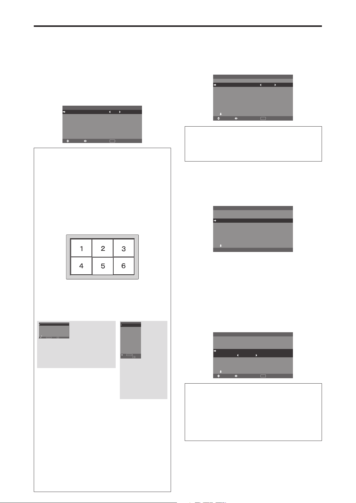
Option1 Settings Menu
Setting the on-screen menu
This sets the position of the menu, the display format
(horizontal or vertical) etc.
Example: Turning the DISPLAY OSM off
On “OPTION1” menu, select “OSM”, then press the MENU/
ENTER button.
The “OSM” menu appears.
On “DISPLAY OSM” of “OSM” menu, select “OFF”.
DISPLAY OSM
OSM ADJ.
OSM ANGLE
OSM ORBITER
OSM CONTRAST
SEL. ADJ. RETURN
Information
DISPLAY OSM settings
ON: The informations on screen size, volume control,
etc. will be shown.
OFF: The informations on screen size, volume control,
etc. will not be shown.
The DISPLAY button on the remote control will not
function either.
OSM ADJUST settings
Adjusts the position of the menu when it appears on the screen.
The position can be set between 1 to 6.
OSM
: OFF
: 1
: H
: OFF
: LOW
EXIT
Setting the BNC input connector type
Select whether to set the input of the 5 BNC connectors to
RGB or Component.
Example: Set the “BNC INPUT” mode to “COMP.”
On “BNC INPUT” of “OPTION1” menu, select “COMP.”.
OSM
BNC INPUT
D-SUB INPUT
RGB SELECT
: AUTO
HD SELECT
INPUT SKIP
ALL RESET
NEXT PAGE
SEL. ADJ. RETURN
OPTION1 1 / 4
: COMP.
: RGB
: 1080B
: OFF
: OFF
EXIT
Information
BNC INPUT Settings
RGB: Use the 5BNC terminals for RGB input.
COMP.: Use the 3BNC terminals for component input.
Checking the signal being transmitted to
RGB1 terminal
Use this to confirm the signal being transmitted to the
RGB1 terminal.
It is set to RGB and can not be adjusted.
OSM
BNC INPUT
D-SUB INPUT
RGB SELECT
: AUTO
HD SELECT
INPUT SKIP
ALL RESET
NEXT PAGE
CAN NOT ADJUST
OPTION1 1 / 4
: RGB
: RGB
: 1080B
: OFF
: OFF
OSM ANGLE settings
Sets the display format (landscape “H” or portrait “V”).
When the unit is installed vertically set the OSM
ANGLE at “V”.
“H”“V”
OPTION1 1 / 4
OSM
BNC INPUT
: RGB
D-SUB INPUT
: RGB
RGB SELECT
: AUTO
HD SELECT
: 1080B
INPUT SKIP
: OFF
ALL RESET
: OFF
NEXT PAGE
MENU/ENTER
SEL. RETURN
OK
EXIT
OPTION1
OSM
BNC INPUT
D-SUB INPUT
RGB SELECT
HD SELECT
INPUT SKIP
ALL RESET
SEL.
MENU/ENTER
: RGB
: RGB
: AUTO
: 1080B
: OFF
: OFF
1024768
OK
EXIT
RETURN
* The menu language for “V” is English only.
* Some menu items including LONG LIFE mode will
not be displayed with “V”, but can be performed by
setting with “H” (See pages 19 and 20 for the menu
items that can be displayed with “V”).
OSM ORBITER settings
ON: The position of the menu will be shifted by eight
dots each time OSM is displayed.
OFF: OSM will be displayed at the same position.
OSM CONTRAST settings
NORMAL: OSM brightness is set to normal.
LOW: OSM brightness is set to lower.
Setting a computer image to the correct RGB
select screen
With the computer image, select the RGB Select mode
for a moving image such as (video) mode, wide mode or
digital broadcast.
Example: Setting the “RGB SELECT” mode to
“852480 ”
On “RGB SELECT” of “OPTION1” menu, select
“852480”.
OSM
BNC INPUT
D-SUB INPUT
RGB SELECT
: 852480
HD SELECT
INPUT SKIP
ALL RESET
NEXT PAGE
SEL. ADJ. RETURN
OPTION1 1 / 4
: RGB
: RGB
: 1080B
: OFF
: OFF
EXIT
Information
RGB SELECT modes
AUTO: Select the suitable mode for the specifications
of input signals as listed in the table “Computer input
signals supported by this system” on page En-42.
The others: The available resolutions are shown.
See page En-42 for the details of the above settings.
En-24
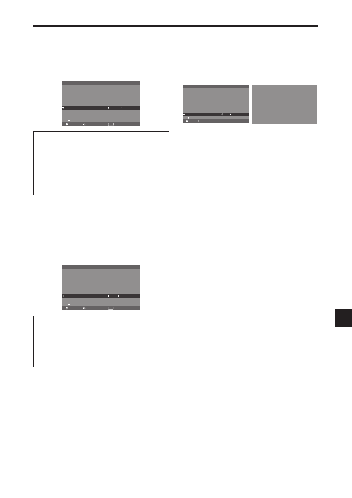
Setting high definition images to the suitable
screen size
Use this procedure to set whether the number of vertical
lines of the input high definition image is 1035 or 1080.
Example: Setting the “HD SELECT” mode to “1035I”
On “HD SELECT” of “OPTION1” menu, select “1035I”.
OSM
BNC INPUT
D-SUB INPUT
RGB SELECT
: AUTO
HD SELECT
INPUT SKIP
ALL RESET
NEXT PAGE
SEL. ADJ. RETURN
OPTION1 1 / 4
: RGB
: RGB
I
1035
:
: OFF
: OFF
EXIT
Information
HD SELECT modes
These 3 modes are not displayed in correct image
automatically.
1080B: Standard digital broadcasts
1035I: Japanese “High Vision” signal format
1080A: Special Digital broadcasts (for example :
DTC100)
Setting the Input Skip
When this is ON, signals which are not present will be
skipped over and only pictures whose signals are being
transmitted will be displayed.
This setting is valid only for the INPUT SELECT button
on the unit.
Example: Set to “ON”
On “INPUT SKIP” of “OPTION1” menu, select “ON”.
OSM
BNC INPUT
D-SUB INPUT
RGB SELECT
: AUTO
HD SELECT
INPUT SKIP
ALL RESET
NEXT PAGE
SEL. ADJ. RETURN
OPTION1 1 / 4
: RGB
: RGB
1080B
:
: ON
: OFF
EXIT
Resetting to the default values
Use these operations to restore all the settings (PICTURE,
AUDIO, IMAGE ADJUST, OPTION1~4, etc.) to the
factory default values.
Refer to page En-19 for items to be reset.
On “ALL RESET” of “OPTION1” menu, select “ON”, then
press the MENU/ENTER button.
OSM
BNC INPUT
D-SUB INPUT
RGB SELECT
: AUTO
HD SELECT
INPUT SKIP
ALL RESET
NEXT PAGE
SEL. RETURN
OPTION1 1 / 4
: RGB
: RGB
1080B
:
: OFF
: ON
MENU/ENTER
EXIT
OK
ALL RESET
SETTING NOW
When the “SETTING NOW” screen disappears, then all the
settings are restored to the default values.
Information
INPUT SKIP settings
OFF: Regardless of the presence of the signal, scan
and display all signals.
ON: If no input signal is present, skip that signal.
* “SETTING NOW” will appear during the input search.
En-25
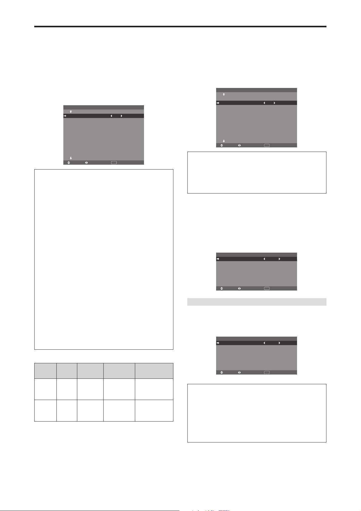
Option2 Settings Menu
Set “ADVANCED OSM” to “ON” in the MAIN MENU.
Setting the power management for computer
images
This energy-saving (power management) function
automatically reduces the monitor’s power consumption
if no operation is performed for a certain amount of time.
Example:
On “PWR. MGT.” of “OPTION2” menu, select “ON”.
Information
䡵 Power management function
* The power management function automatically reduces
the monitor’s power consumption if the computer’s
keyboard or mouse is not operated for a certain amount
of time. This function can be used when using the
monitor with a computer.
* If the computer’s power is not turned on or if the
computer and selector tuner are not properly connected,
the system is set to the off state.
* For instructions on using the computer’s power
management function, refer to the computer’s operating
instructions.
䡵 Power management settings
ON: In this mode the power management function is
turned on.
OFF: In this mode the power management function is
turned off.
䡵 Power management function and POWER/
The POWER/STANDBY indicator indicates the status
of the power management function. See below for
indicator status and description.
POWER/STANDBY indicator
Power
management
mode
On
Off
Turning the power management function on
PREVIOUS PAGE
PWR. MGT.
CINEMA MODE
LONG LIFE
GRAY LEVEL
S1/S2
PICTURE SIZE
DVI SET UP
PROTOCOL SET
CLOSECAPTION
CAPTION CONT
NEXT PAGE
SEL. ADJ. RETURN
OPTION2 2 / 4
: ON
: ON
: 3
: OFF
: ON
: OFF
: OFF
: LOW
EXIT
STANDBY indicator
POWER/
STANDBY
indicator
Green
Red
Power
management
operating status
Not activated.
Activated.
Description
Horizontal and vertical
synchronizing signals
are present from the
computer.
Horizontal and/or
vertical synchronizing
signals are not sent
from the computer.
Turning the picture
back on
Picture already on.
Operate the keyboard or
mouse. The picture
reappears.
Setting the picture to suit the movie
The film image is automatically discriminated and
projected in an image mode suited to the picture.
[NTSC, PAL, PAL60, 480I (60 Hz), 525I (60 Hz), 576I
(50 Hz), 625I (50 Hz), 1035I (60 Hz), 1080I (60 Hz) only]
Example: Setting the “CINEMA MODE” to “OFF”
On “CINEMA MODE” of “OPTION2” menu, select “OFF”.
PREVIOUS PAGE
PWR. MGT.
CINEMA MODE
LONG LIFE
GRAY LEVEL
S1/S2
PICTURE SIZE
DVI SET UP
PROTOCOL SET
CLOSECAPTION
CAPTION CONT
NEXT PAGE
SEL. ADJ. RETURN
OPTION2 2 / 4
: OFF
: OFF
: 3
: OFF
: ON
: OFF
: OFF
: LOW
EXIT
Information
䡵 CINEMA MODE
ON: Automatic discrimination of the image and
projection in cinema mode.
OFF: Cinema mode does not function.
Reducing image retention
The brightness of the screen, the position of the picture,
positive/negative mode and screen wiper are adjusted to
reduce image retention.
On “OPTION2” menu, select “LONG LIFE”, then press the
MENU/ENTER button.
The “LONG LIFE” screen appears.
PLE
ORBITER
INVERSE
SCREEN WIPER
SOFT FOCUS
SEL. ADJ. RETURN
LONG LIFE
: AUTO
: AUTO1
: OFF
: OFF
: OFF
EXIT
PLE (Peak Luminance Enhancement)
Use this to activate the brightness limiter.
Example: Setting “PLE” to “LOCK1”
On “PLE” of “LONG LIFE” menu, select “LOCK1”.
PLE
ORBITER
INVERSE
SCREEN WIPER
SOFT FOCUS
SEL. ADJ. RETURN
LONG LIFE
: LOCK1
: AUTO1
: OFF
: OFF
: OFF
EXIT
Information
䡵 PLE settings
AUTO: The brightness of the screen is adjusted
automatically to suit the picture quality.
LOCK1, 2, 3: Sets maximum brightness.
The brightness level decreases in the order of LOCK
1, 2, 3. LOCK 3 provides minimum brightness.
En-26
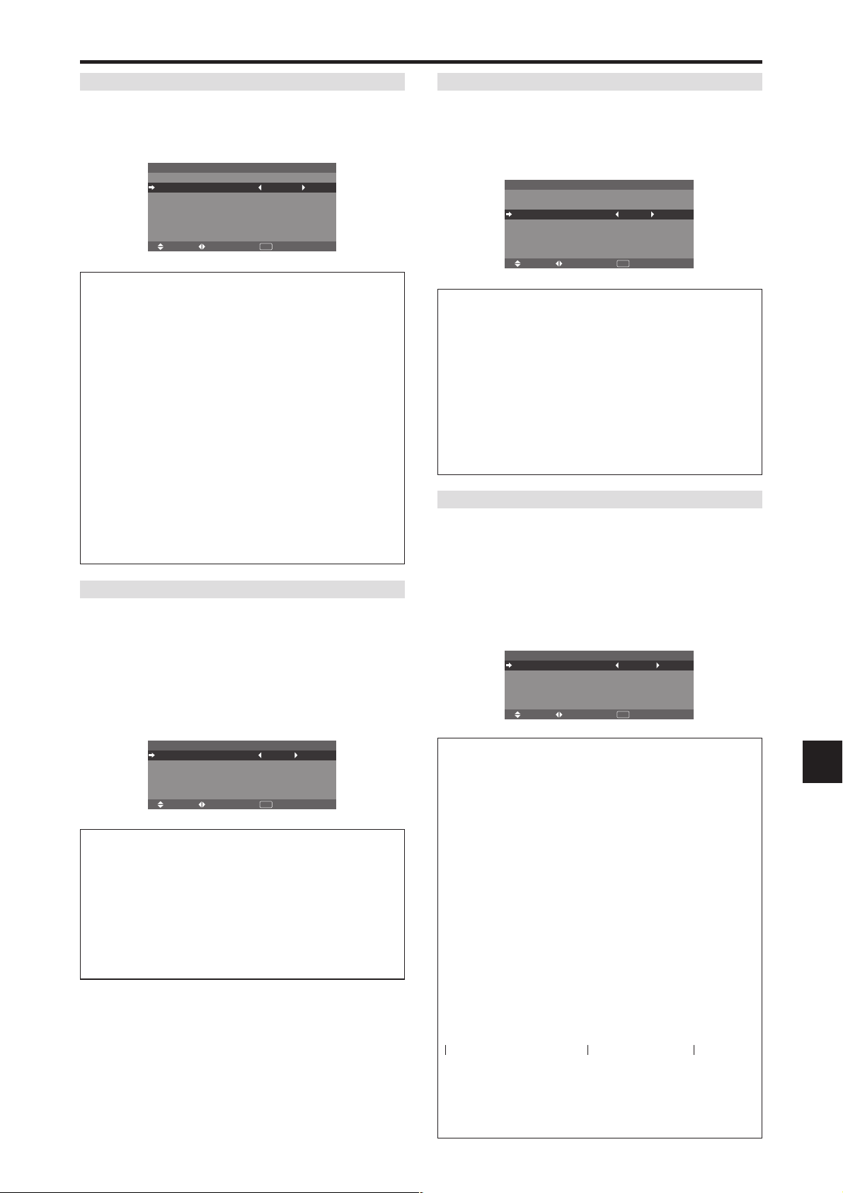
ORBITER
Use this to set the picture shift.
Example: Setting “ORBITER” to “AUTO2”
On “ORBITER” of “LONG LIFE” menu, select “AUTO2”.
PLE
ORBITER
INVERSE
SCREEN WIPER
SOFT FOCUS
SEL. ADJ. RETURN
LONG LIFE
: AUTO
: AUTO2
: OFF
: OFF
: OFF
EXIT
Information
䡵 ORBITER settings
OFF: Orbiter mode does not function.
This is the default setting when RGB is input.
AUTO1: The picture moves around the screen
intermittently, making the picture smaller. This is the
default setting when a Video or a DVD/HD/DTV signal
is input. Set to “OFF” when these signals are not used.
AUTO2: The picture moves around the screen
intermittently, making the picture bigger.
MANUAL: User can adjust the orbiter function
(Horizontal Dot, Vertical Line and Time) manually.
See the following explanation.
* When a Video or a DVD/HD/DTV signal is input, the
AUTO1 and 2 functions will affect only the moving
picture and will not make the screen smaller or bigger.
Adjust the ORBITER function manually
Set the amount of shift and the time between movement.
Example: Setting so that the picture moves 2 dots
horizontally and 4 lines vertically every 3 minutes.
On “ORBITER” of “LONG LIFE” menu, select
“MANUAL”, then press the MENU/ENTER button.
THE “ORBITER” screen appears.
Adjust the items.
H-DOT
V-LINE
TIME
SEL. ADJ. RETURN
ORBITER
: 2DOT
: 4LINE
: 3M
EXIT
Information
䡵 ORBITER Function settings
H-DOT: Moves from 1 dot to 20 dots in the horizontal
direction.
V-LINE: Moves from 1 line to 20 lines in the vertical
direction.
TIME: Interval of 1 minute to 5 minutes (1 horizontal
dot or 1 vertical line per interval).
INVERSE
Use this to set the inverse mode or to display a white
screen.
Example: Setting “INVERSE” to “WHITE”
On “INVERSE” of “LONG LIFE” menu, select “WHITE”.
PLE
ORBITER
INVERSE
SCREEN WIPER
SOFT FOCUS
SEL. ADJ. RETURN
LONG LIFE
: AUTO
: AUTO1
: WHITE
: OFF
: OFF
EXIT
Information
䡵 INVERSE Settings
ON: The picture is displayed alternately between
positive image and negative image.
You can set the time by pressing the MENU/ENTER
button while “ON” is set.
OFF: Inverse mode does not function.
WHITE: The entire screen turns white.
You can set the time by pressing the MENU/ENTER
button while “ON” is set.
Setting the time for INVERSE/WHITE
Set a time duration.
Example: Setting to that the INVERSE mode starts
in 2 hours and proceeds for one hour and a half.
On “INVERSE” of “LONG LIFE” menu, select “ON”, then
press the MENU/ENTER button.
THE “INVERSE/WHITE” screen appears.
Adjust the times.
WORKING TIME
WAITING TIME
INVERSE/WHITE
SEL. ADJ. RETURN
: 01H30M
: 02H00M
EXIT
Information
䡵 Setting the time
WORKING TIME: Set the time duration for
“INVERSE/WHITE”.
When the WORKING TIME is set to “ON” the mode
will stay on.
WAITING TIME: Set the standby time until the
“INVERSE/WHITE” mode starts.
* The “WAITING TIME” can not be set when the
“WORKING TIME” is ON.
THE “WORKING TIME” and “WAITING TIME” can be
*
set for up to 12 hours and 45 minutes in units of 3 minutes.
* Ending a WORKING TIME function, the monitor will
go to STANDBY.
[Example]
WORKING TIME: 01H30M
WAITING TIME: 02H00M
←−−−− 2 H −−−−→←−− 1.5 H −−→←−−−−
Start INVERSE/WHITE Start STANDBY
䡵 To select “ON” for the “WORKING TIME”...
Set the hours of the working time to 0H and the minutes
to 0M. “ON” will be displayed.
En-27
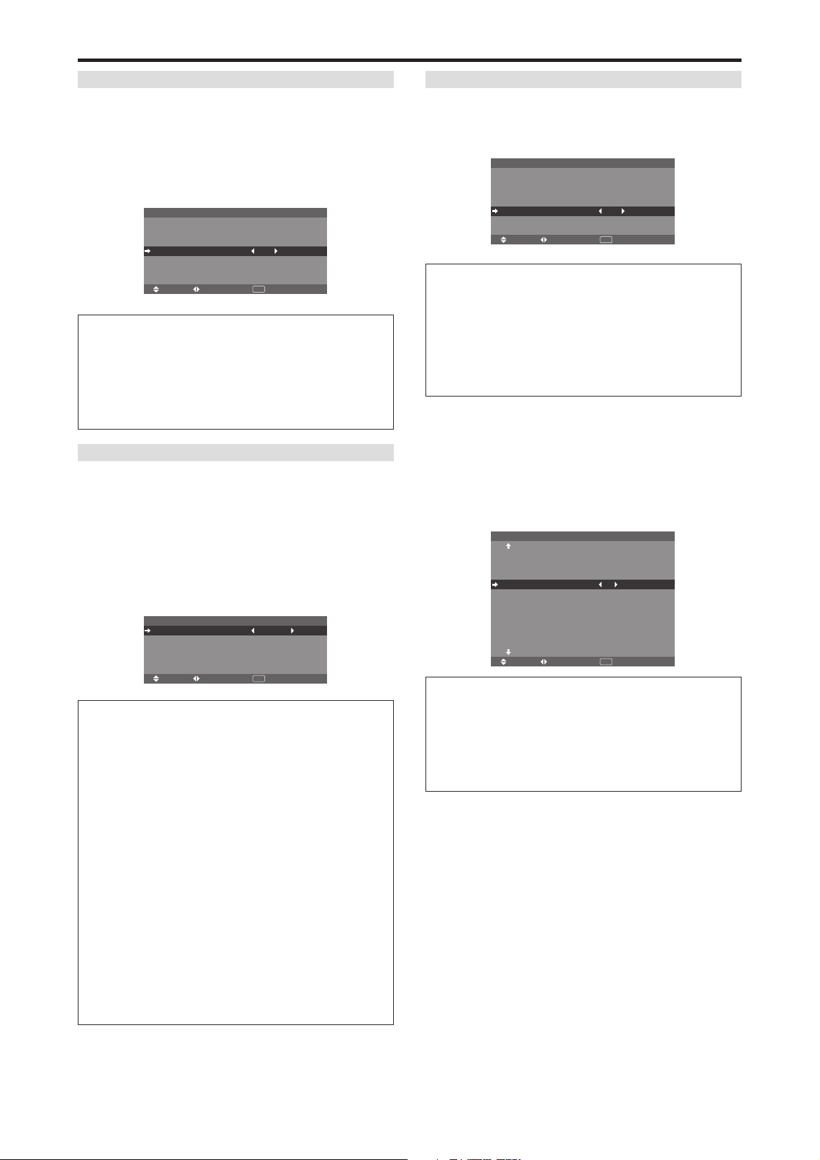
SCREEN WIPER
When this is set to ON, a white vertical bar moves
repeatedly from the left and of the screen to the right end
at a constant speed.
Example: Setting “SCREEN WIPER” to “ON”
On “SCREEN WIPER” of “LONG LIFE” menu, select
“ON”.
PLE
ORBITER
INVERSE
SCREEN WIPER
SOFT FOCUS
SEL. ADJ. RETURN
LONG LIFE
: AUTO
: AUTO1
: OFF
: ON
: OFF
EXIT
Information
䡵 SCREEN WIPER
ON: The white vertical bar appears.
You can set the time by pressing the MENU/ENTER
button while “ON” is set.
OFF: Screen wiper mode does not function.
Setting the time for SCREEN WIPER
Set a time duration and the speed.
Example: Setting so that the SCREEN WIPER mode
starts in 30 minutes and proceeds for one and a half
hours.
On “SCREEN WIPER” of “LONG LIFE” menu, select
“ON”, then press the MENU/ENTER button.
THE “SCREEN WIPER” screen appears.
Adjust the times and speed.
WORKING TIME
WAITING TIME
SPEED
SCREEN WIPER
SEL. ADJ. RETURN
: 01H30M
: 00H30M
: 3
EXIT
Information
䡵 Setting the time
WORKING TIME: Set the time duration for “SCREEN
WIPER”.
When the WORKING TIME is set to “ON” the mode
will stay on.
WAITING TIME: Set the standby time until the
“SCREEN WIPER” mode starts.
SPEED: Set the moving speed for the “SCREEN
WIPER”. The speed decreases as the number increases.
* The “WAITING TIME” can not be set when the
“WORKING TIME” is ON.
* THE “WORKING TIME” and “WAITING TIME” can
be set for up to 12 hours and 45 minutes in units of 3
minutes.
䡵 To select “ON” for the “WORKING TIME”...
Set the hours of the working time to 0H and the minutes
to 0M. “ON” will be displayed.
SOFT FOCUS
Reduces edges and softens the image.
Example: Setting “SOFT FOCUS” to “2”
On “SOFT FOCUS” of “LONG LIFE” menu, select “2”.
PLE
ORBITER
INVERSE
SCREEN WIPER
SOFT FOCUS
SEL. ADJ. RETURN
LONG LIFE
: AUTO
: AUTO1
: OFF
: OFF
: 2
EXIT
Information
䡵 SOFT FOCUS settings
OFF: Turns the SOFT FOCUS function off.
1, 2, 3, 4: Activates the SOFT FOCUS setting. The
higher numbers create a softer image.
“SHARPNESS” can not be adjusted in the “PICTURE”
menu.
Setting the gray level for the sides of the
screen
Use this procedure to set the gray level for the parts on the
screen on which nothing is displayed when the screen is
set to the 4:3 size.
Example: Setting “GRAY LEVEL” to “5”
On “GRAY LEVEL” of “OPTION2” menu, select “5”.
PREVIOUS PAGE
PWR. MGT.
CINEMA MODE
LONG LIFE
GRAY LEVEL
S1/S2
PICTURE SIZE
DVI SET UP
PROTOCOL SET
CLOSECAPTION
CAPTION CONT
NEXT PAGE
SEL. ADJ. RETURN
OPTION2 2 / 4
: OFF
: ON
: 5
: OFF
: ON
: OFF
: OFF
: LOW
EXIT
Information
䡵 GRAY LEVEL settings
This adjusts the brightness of the black (the gray level)
for the sides of the screen.
The standard is 0 (black). The level can be adjusted
from 0 to 15. The factory setting is 3 (dark gray).
En-28
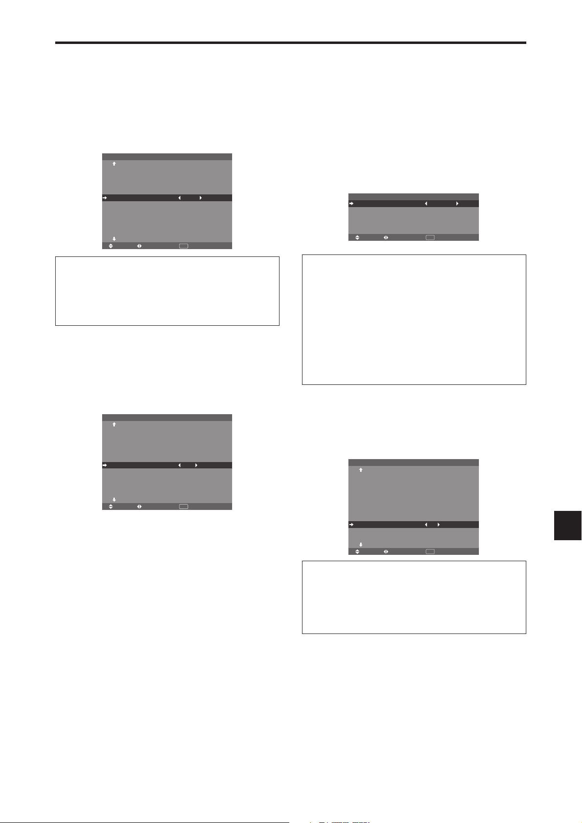
Setting the screen size for S1/S2 video input
If the S-video signal contains screen size information, the
image will be automatically adjusted to fit the screen when
this S1/S2 is set to AUTO.
This feature is available only when an S-video signal is
input via the VIDEO3 terminal.
Example: Setting “S1/S2” to “AUTO”
On “S1/S2” of “OPTION2” menu, select “AUTO”.
PREVIOUS PAGE
PWR. MGT.
CINEMA MODE
LONG LIFE
GRAY LEVEL
S1/S2
PICTURE SIZE
DVI SET UP
PROTOCOL SET
CLOSECAPTION
CAPTION CONT
NEXT PAGE
SEL. ADJ. RETURN
OPTION2 2 / 4
: OFF
: ON
: 3
: AUTO
: ON
: OFF
: OFF
: LOW
EXIT
Setting the signal and black level for DVI
signal
Choose the signal for the DVI connector (PC or STB/
DVD) and set the black level.
Example: Setting the “PLUG/PLAY” mode to “STB/
DVD”
On “OPTION2” menu, select “DVI SET UP”, then press the
MENU/ENTER button.
The “DVI SET UP” screen appears.
On “PLUG/PLAY” of “DVI SET UP” menu, select “STB/
DVD”.
PLUG/PLAY
BLACK LEVEL
SEL. ADJ. RETURN
DVI SET UP
: STB/DVD
: HIGH
EXIT
Information
䡵 S1/S2 settings
AUTO: Adjusts the screen size automatically according
to the S1/S2 video signal.
OFF: Turns the S1/S2 function off.
Setting the picture size for RGB input signals
Use this procedure to switch the setting to “ON” or “OFF”.
* This function is available only for 50 and 60 inch types.
Example: Setting the “PICTURE SIZE” mode to
“OFF”
On “PICTURE SIZE” of “OPTION2” menu, select “OFF”.
PREVIOUS PAGE
PWR. MGT.
CINEMA MODE
LONG LIFE
GRAY LEVEL
S1/S2
PICTURE SIZE
DVI SET UP
PROTOCOL SET
CLOSECAPTION
CAPTION CONT
NEXT PAGE
SEL. ADJ. RETURN
OPTION2 2 / 4
: OFF
: ON
: 3
: OFF
: OFF
: OFF
: OFF
: LOW
EXIT
Information
䡵 PLUG/PLAY settings
PC: When connected to the PC signal.
BLACK LEVEL is set to “LOW” automatically.
STB/DVD:
When connected to the SET TOP BOX, DVD etc.
BLACK LEVEL is set to “HIGH” automatically.
䡵 BLACK LEVEL settings
LOW: When connected to the PC signal.
HIGH:
When connected to the SET TOP BOX, DVD etc.
Change “HIGH” into “LOW” if the black level appears gray.
Setting the Protocol set
Use this setting when connecting a device which uses
special protocol for RS-232C communication.
Example: Setting “ON”
On “PROTOCOL SET” of “OPTION2” menu, select “ON”.
PREVIOUS PAGE
PWR. MGT.
CINEMA MODE
LONG LIFE
GRAY LEVEL
S1/S2
PICTURE SIZE
DVI SET UP
PROTOCOL SET
CLOSECAPTION
CAPTION CONT
NEXT PAGE
SEL. ADJ. RETURN
OPTION2 2 / 4
: OFF
: ON
: 3
: OFF
: ON
: ON
: OFF
: LOW
EXIT
Information
䡵 PROTOCOL SET settings
ON: When special protocol is used.
OFF: When NEC protocol is used (normal).
* Consult your dealer for details of protocol.
En-29

Setting CloseCaption
Choose the closed caption mode that allows text to be
superimposed in the active video.
Example: Setting “CLOSECAPTION” to “CC2”
On “CLOSECAPTION” of “OPTION2” menu, select
“CC2”.
PREVIOUS PAGE
PWR. MGT.
CINEMA MODE
LONG LIFE
GRAY LEVEL
S1/S2
PICTURE SIZE
DVI SET UP
PROTOCOL SET
CLOSECAPTION
CAPTION CONT
NEXT PAGE
SEL. ADJ. RETURN
OPTION2 2 / 4
: OFF
: ON
: 3
: OFF
: ON
: OFF
: CC2
: LOW
EXIT
Option3 Settings Menu
Set “ADVANCED OSM” to “ON” in the MAIN MENU.
Using the timer
This function sets the day of the week and time. You can
also set the program timer which turns on or off the power
at the day of the week, time and the input mode you want,
or repeat timer which displays two input modes alternately.
On “OPTION3” menu, select “TIMER”, then press the
MENU/ENTER button.
The “TIMER” screen appears.
PRESENT TIME
TIMER : OFF
SEL. RETURN
TIMER
MENU/ENTER
OK
EXIT
Information
䡵 CLOSECAPTION settings
OFF: This exits the closed caption mode.
CC1~4: Text is superimposed.
TEXT1~4: Text is displayed in full screen.
A closed caption signal may not be decoded in the
following signature;
1. when a video tape has been dubbed.
2. when the signal reception is weak.
3. when the signal reception is nonstandard.
When using closed captioned channel or the text mode,
the text screen always appears.
When there is no signal, however, the text screen will
not display text characters.
Setting the contrast of CloseCaption
Choose the brightness of the closed caption.
Example: Setting “CAPTION CONT” to “NORMAL”
On “CAPTION CONT” of “OPTION2” menu, select
“NORMAL”.
PREVIOUS PAGE
PWR. MGT.
CINEMA MODE
LONG LIFE
GRAY LEVEL
S1/S2
PICTURE SIZE
DVI SET UP
PROTOCOL SET
CLOSECAPTION
CAPTION CONT
NEXT PAGE
SEL. ADJ. RETURN
OPTION2 2 / 4
: OFF
: ON
: 3
: OFF
: ON
: OFF
: OFF
: NORMAL
EXIT
Information
䡵 CAPTION CONT settings
NORMAL: Closed Caption brightness is set to normal.
LOW: Closed Caption brightness is set to lower.
PRESENT TIME
This sets the day of the week and present time.
Example: Setting “WEDNESDAY”, “22:05”
On “TIMER” menu, select “PRESENT TIME”, then press
the MENU/ENTER button.
The “PRESENT TIME” screen appears.
Adjust the items.
RETURN
DAYLIGHT
SAVING TIME
SET
SEL. ADJ. RETURN
PRESENT TIME
: OFF
WEDNESDAY
22 : 05 : 00
EXIT
Select “SET”, then press the MENU/ENTER button.
The adjustments are stored and the TIMER menu reappears.
* If you press the EXIT button instead of the MENU/ENTER
button, the settings can not be made.
RETURN
DAYLIGHT
SAVING TIME
SET
SEL. RETURN
PRESENT TIME
WEDNESDAY
22 : 05 : 00
MENU/ENTER
OK
: OFF
EXIT
Information
䡵 PRESENT TIME settings
DAYLIGHT SAVING TIME: Use to set DAYLIGHT
SAVING TIME.
ON: The present time + 1 hour.
OFF: Cancelled
Day: Set the day of the week (e.g. Sunday).
Hour: Set the hour in the 24-hour format (range 00 to
23).
Minutes: Set the minutes (range 00 to 59).
En-30

PROGRAM TIMER
DAY
MON
TUE
SAT
*FRI
—
SAT
*
—
INPUT
RGB2
—
VIDEO1
DVD1
—
—
RGB1
—
FUNC.
INV.
—
WHITE
—
—
REP.1
—
—
ON
08 : 30
- - : - 08 : 30
08 : 30
- - : - 08 : 30
15 : 30
- - : - -
OFF
10 : 30
18 : 15
12 : 15
10 : 00
- - : - 12 : 15
16 : 00
- - : - -
1
2
3
4
5
6
7
8
PROGRAM TIMER
This sets the day and time at which the power will be
switched ON/OFF as well as the input mode.
Example 1: Setting so that the power will be switched
on at 8:30 A.M., Monday, displaying RGB2 source,
and switched off at 10:30 A.M.
On “TIMER” menu, select “PROGRAM”, then press the
MENU/ENTER button.
The “PROGRAM TIMER” screen appears.
Adjust the items.
䊴 䊳
Use the ▲▼ and
buttons to move the cursor.
Each mode switches each time the ZOOM Ⳮ/ⳮ button is
pressed.
Depending on the selected INPUT or FUNC., press the
MENU/ENTER button to make advanced settings.
PROGRAM TIMER
INPUT
RGB2
—
—
—
—
—
—
—
—
—
FUNC.
INV.
—
—
—
—
—
—
—
—
—
EXIT
DAY
MON
1
—
2
—
3
—
4
—
5
—
6
—
7
—
8
—
9
—
10
SEL. OK
08 : 30
- - : - -
- - : - -
- - : - -
- - : - -
- - : - -
- - : - -
- - : - -
- - : - -
- - : - -
ZOOM
10 : 30
- - : - -
- - : - -
- - : - -
- - : - -
- - : - -
- - : - -
- - : - -
- - : - -
- - : - -
ADJ.
OFF
ON
Example 2: Setting so that the power will be switched
on at 8:00 A.M., Monday, displaying the VIDEO1
input, display the RGB1 input at 9:00 A.M., display in
WHITE at 10:00 A.M., then switched off at 11:00 A.M.
8:00 9:00 10:00 11:00
1
2
3
4
ON
DAY
MON
MON
MON
—
VIDEO1
08 : 00
09 : 00
10 : 00
- - : - -
PROGRAM TIMER
OFF
ON
- - : - -
- - : - -
11 : 00
- - : - -
VIDEO1
RGB1
INPUT
RGB1
—
—
FUNC.
—
—
WHITE
—
WHITE
PROGRAM 1
PROGRAM 2
PROGRAM 3
* To perform a continuous program, set the OFF time only
for the last item.
Information
䡵 PROGRAM TIMER settings
DAY: Set the day of the week (e.g. Sunday).
ON (hour, minutes): Set the time at which the power
will be turned on in the 24-hour format.
OFF (hour, minutes): Set the time at which the power
will be turned off in the 24-hour format.
INPUT: Set the input mode that will be displayed when
the power is turned on from “VIDEO1~3”, “DVD1~2”,
“RGB1~3” and “MULTI”.
FUNC.: Set the function that will be activated after the
power is turned on from “ORB.”, “INV.”, “WHITE”,
“WIPER” and “REP.1~3”.
“REP.1~3” cannot be selected when INPUT is set.
䡵 To reset the program
Align the cursor with the DAY field that you wish to
reset, then press the CLEAR/SEAMLESS SW button.
䡵 To reset the data
Align the cursor with the field (ON/OFF/INPUT/
FUNC.) that you wish to reset, then press the CLEAR/
SEAMLESS SW button.
OFF
䡵 Special characters in the PROGRAM TIMER
screen
When the setting item includes gray indication, it does
not function under the timer’s setting.
• An asterisk “*” in the DAY field
An asterisk “*” means “every” or “everyday”. For
example, “*FRI” means “every Friday”. If you enter
“*” only, it means “everyday”.
• A hyphen “-” in the ON field or OFF field
You have to set at least the ON field or OFF field to
activate the program timer.
• A hyphen “-” in the INPUT and FUNC. field
A hyphen “-” in the INPUT field means the last mode.
When you set “REP.1~3” in the FUNC. field, the
INPUT field is set to “-”.
䡵 To set MULTI INPUT
• Set the INPUT field to “MULTI”, then press the
MENU/ENTER button.
The “MULTI SCREEN SETTING” will appear on
the screen.
• Use the ▲ and ▼ buttons to select “MULTI MODE”,
䊴
then use the
and 䊳 buttons to choose from
“SINGLE”, “SIDE BY SIDE1~3” and “PICTURE
IN PICTURE (BOTTOM LEFT~TOP LEFT)”.
• Use the ▲ and ▼ buttons to select “MAIN”/ “SUB”
and “LEFT”/“RIGHT”, then use the
䊴
and 䊳 buttons
to choose from “VIDEO1~3”, “DVD1~2” and
“RGB1~3”.
PICTURE IN PICTURE SIDE BY SIDE
PROGRAM TIMER
MULTI SCREEN SETTING
MULTI MODE
: BOTTOM LEFT
INPUT MODE
MAIN
SUB
SEL. ADJ. RETURN
: RGB1
: VIDEO1
EXIT
PROGRAM TIMER
MULTI SCREEN SETTING
MULTI MODE
: SIDE BY SIDE1
INPUT MODE
LEFT
RIGHT
SEL. ADJ. RETURN
: RGB1
: VIDEO1
䡵 To set “REP.1~3” to the FUNC.
• Set the function to “REP.1”, “REP.2” or “REP.3”, then
press the MENU/ENTER button.
The “REPEAT TIMER” screen will appear on the
screen.
䊴
• Use the
and 䊳 buttons to choose from “SINGLE”,
“MULTI” and “VIDEO-W”, then adjust the items.
• When you set FUNC. to “REP.1”, “REP.2” or
“REP.3”, you can set “SINGLE”, “MULTI” and
“VIDEO-W”. However, only one of these works
depending on the settings of AUTO ID and DIVIDER.
See “REPEAT TIMER” on page En-31 for details
for the above settings.
REPEAT TIMER
This function enables you to display 2 input modes at the
set time alternately.
Example: Setting to display “VIDEO1” for 10 minutes
and “DVD1” for 15 minutes alternately.
On “TIMER” menu, select “REPEAT”, then press the
MENU/ENTER button.
En-31
EXIT

The “REPEAT TIMER” screen appears.
Adjust the items.
䊴
Use the
and 䊳 buttons to select “SINGLE”.
Use the ▲ and ▼ buttons to select the item, then press the
and 䊳 buttons to set.
REPEAT TIMER
1 WORK TIME
INPUT MODE
2 WORK TIME
INPUT MODE
SEL. ADJ. RETURN
REPEAT TIMER
: SINGLE
: 00H10M
: VIDEO1
: 00H15M
: DVD1
EXIT
Information
䡵 REPEAT TIMER function
* The two repeat timers run consecutively, i.e., Timer 1-
Timer 2-Timer1-Timer2.
* This becomes effective when the on-screen menu goes
out.
䡵 SINGLE settings
WORK TIME: Set the time duration of the display.
Time range is from 1 minute to 24 hours.
INPUT MODE: Set the signal that will be displayed.
* Set the DIVIDER “OFF” and ID NUMBER “ALL”
before the operation.
䡵 MULTI settings
MODE: Select the input mode to be displayed from
“SINGLE”, “S BY S1~3” and “ PICTURE IN
PICTURE (BTM LFT~TOP LFT)”.
WORK TIME: Set the time duration of the display.
Time range is from 1 minute to 24 hours.
INPUT MODE: Set the signal that will be displayed.
Select “MAIN” or “SUB” for “PICTURE IN PICTURE
(BTM LFT~TOP LFT)” and “LEFT” or “RIGHT” for
“S BY S1~3”.
Only one signal is selected for “SINGLE”.
REPEAT TIMER
1 MODE
WORK TIME
INPUT MODE
MAIN
SUB
2 MODE
WORK TIME
INPUT MODE
LEFT
RIGHT
SEL. ADJ. RETURN
REPEAT TIMER
: MULTI
: BTM LFT
: 04H00M
: RGB1
: VIDEO1
: S BY S1
: 02H30M
: RGB3
: DVD1
EXIT
* Set the DIVIDER “OFF” and ID NUMBER “ALL”
before the operation.
䡵 VIDEO WALL settings
DIVIDER: Divide the screens into 1, 2⳯2 or 3⳯3
sections.
WORK TIME: Set the time duration of the display.
Time range is from 1 minute to 24 hours.
INPUT MODE: Set the signal that will be displayed.
* Turn on the AUTO ID and set the DIVIDER (at 1, 2⳯2
or 3⳯3) before the operations.
* In the case of Video Wall, timer No.1 can be used to
control all the displays simultaneously.
REPEAT TIMER
1 DIVIDER
WORK TIME
INPUT MODE
2 DIVIDER
WORK TIME
INPUT MODE
SEL. ADJ. RETURN
REPEAT TIMER
: VIDEO WALL
: 1
: 00H03M
: VIDEO1
: 2⳯ 2
: 00H06M
: RGB1
EXIT
䊴
Setting the power on mode
This function sets the input mode and the sound volume
at the time the power is switched on.
Example: Setting the input mode to “VIDEO2”
On “OPTION3 ” menu, select “PWR.ON MODE ”, then
press the MENU/ENTER button.
The “PWR.ON MODE ” screen appears.
On “INPUT ” of “PWR.ON MODE ” menu, select
“VIDEO2”.
The available inputs depend on the setting of input.
INPUT
VOLUME
SEL. ADJ. RETURN
PWR. ON MODE
: VIDEO2
: LAST
EXIT
Information
䡵 INPUT settings
LAST: Last mode (the input that was last selected at
the time the power was switched off).
VIDEO1, 2, 3: VIDEO input mode.
RGB1, 2, 3: RGB input mode.
DVD/HD1, 2: DVD/HD input mode.
MULTI: Multi screen mode.
Follow the procedure used for PROGRAM TIMER. See
page En-31.
PICTURE IN PICTURE SIDE BY SIDE
PWR. ON MODE
MULTI SCREEN SETTING
MULTI MODE
: BOTTOM LEFT
INPUT MODE
MAIN
SUB
SEL. ADJ. RETURN
: DVD/HD1
: VIDEO1
EXIT
PWR. ON MODE
MULTI SCREEN SETTING
MULTI MODE
: SIDE BY SIDE1
INPUT MODE
LEFT
RIGHT
SEL. ADJ. RETURN
: DVD/HD1
: VIDEO1
䡵 VOLUME settings
LAST: Last mode (the volume that was last selected at
the time the power was switched off).
0 to 42: The level of sound volume.
Enabling/disabling the front panel controls
This function enables/disables the front panel controls.
Example: Setting “ON”
On “CONTROL LOCK” of “OPTION3” menu, select
“ON”, then press the MENU/ENTER button.
PREVIOUS PAGE
TIMER
PWR. ON MODE
CONTROL LOCK
IR REMOTE
LOOP OUT
REMOTE ID
ID NUMBER
VIDEO WALL
NEXT PAGE
SEL. ADJ. RETURN
OPTION3 3 / 4
: ON
: ON
: OFF
: ALL
: ALL
EXIT
Information
䡵 CONTROL LOCK settings
ON: Disables the buttons on the front panel.
OFF: Enables the buttons on the front panel.
* Even when the CONTROL LOCK is set, the POWER
switch will not be locked.
* This becomes effective when the on-screen menu goes
out.
En-32
EXIT

Enabling/disabling remote control wireless
transmission
This function enables/disables remote control wireless
transmission.
Example: Setting “OFF”
On “IR REMOTE” of “OPTION3” menu, select “OFF”, then
press the MENU/ENTER button.
PREVIOUS PAGE
TIMER
PWR. ON MODE
CONTROL LOCK
IR REMOTE
LOOP OUT
REMOTE ID
ID NUMBER
VIDEO WALL
NEXT PAGE
SEL. ADJ. RETURN
OPTION3 3 / 4
: OFF
: OFF
: OFF
: ALL
: ALL
EXIT
Information
䡵 IR REMOTE settings
ON: Enables remote control wireless transmission.
OFF: Disables remote control wireless transmission.
Set “OFF” to avoid unwanted control from other remote
controls.
Loop Out setting
When this feature is set to ON, the received signal will be
looped out.
Example: Setting “ON”
On “LOOP OUT” of “OPTION3” menu, select “ON”.
PREVIOUS PAGE
TIMER
PWR. ON MODE
CONTROL LOCK
IR REMOTE
LOOP OUT
REMOTE ID
ID NUMBER
VIDEO WALL
NEXT PAGE
SEL. ADJ. RETURN
OPTION3 3 / 4
: OFF
: ON
: ON
: ALL
: ALL
EXIT
Information
䡵 LOOP OUT settings
ON: The received signal will be looped out via RGB1
terminal or VIDEO1 terminal.
OFF: The received signal will not loop out.
* Even if LOOP OUT is ON, signals won’t be sent out if
POWER is being turned off.
䡵 To connect another display...
See page En-6.
䡵 If the RGB1 signal is present at the time the
power switched on...
The RGB1 input will be displayed regardless of the
setting of LOOP OUT.
REMOTE ID setting
Set the remote code to adapt the plasma monitor to the
remote control.
Example: Setting to “1”
On the “REMOTE ID” of “OPTION3” menu, select “1”.
PREVIOUS PAGE
TIMER
PWR. ON MODE
CONTROL LOCK
IR REMOTE
LOOP OUT
REMOTE ID
ID NUMBER
VIDEO WALL
NEXT PAGE
SEL. ADJ. RETURN
OPTION3 3 / 4
: OFF
: ON
: OFF
: 1
: ALL
EXIT
• Press and hold the POWER ON button, and release the
button when the indication saying that the code is set is
displayed. Or, press and hold the POWER STANDBY
button, and release the button when the power is turned
off.
Information
䡵 REMOTE ID setting
ALL: The remote code is not set.
1 to 4: The specified remote code is applied.
ID number setting
When using more than one of these displays, this function
sets ID numbers so that operation of the remote control
does not cause multiple monitors to operate at the same
time.
Example: Setting “2”
On “ID NUMBER” of “OPTION3” menu, select “2”.
PREVIOUS PAGE
TIMER
PWR. ON MODE
CONTROL LOCK
IR REMOTE
LOOP OUT
REMOTE ID
ID NUMBER
VIDEO WALL
NEXT PAGE
SEL. ADJ. RETURN
OPTION3 3 / 4
: OFF
: ON
: OFF
: ALL
: 2
EXIT
* To reset back to ALL
Press the CLEAR/SEAMLESS SW button.
Information
䡵 ID NUMBER settings
ALL: ID NUMBER will not be set.
1 to 256: ID NUMBER will be set.
䡵 When the ID NUMBER have been set
You can also set ID NUMBER for each remote control
to operate the plasma display individually. To do so,
see below.
To set the ID number for the remote control
Example: Setting “2”
Press the ID SELECT button on the remote control.
The “ID SELECT” screen appears.
On “ID NUMBER” of “ID SELECT” menu, select “2”.
ID SELECT
POSITION : 1
ID NUMBER
ADJ. RETURN
: 2
EXIT
* To reset back to ALL
Press the CLEAR/SEAMLESS SW button.
En-33

Video Wall setting
Use this feature to configure a (2⳯2, 3⳯3, 4⳯4, 5⳯5,
5⳯1, 1⳯5) video wall.
On “OPTION3” menu, select “VIDEO WALL”, then press
the MENU/ENTER button.
The “VIDEO WALL” screen appears.
VIDEO WALL
: OFF
: SPLIT
: OFF
: OFF
: OFF
EXIT
Note:
DIVIDER
POSITION
DISP. MODE
AUTO ID
IMAGE ADJUST
P. ON DELAY
PLE LINK
SEL. ADJ. RETURN
A contingency method of shutting off the electric
power should be used in cases of emergency during video
wall setup.
DIVIDER
Set the video wall.
Example: Setting “2⳯2”
On “DIVIDER” of “VIDEO WALL” menu, select “2⳯2”.
DIVIDER
POSITION
DISP. MODE
AUTO ID
IMAGE ADJUST
P. ON DELAY
PLE LINK
SEL. ADJ. RETURN
VIDEO WALL
: 2⳯ 2
: SPLIT
: OFF
: OFF
: OFF
EXIT
Information
䡵 DIVIDER settings
OFF, 1: 1 Screen (Matrix display function does not work)
2⳯2: 4 Screens
3⳯3: 9 Screens
4⳯4: 16 Screens
5⳯5: 25 Screens
5⳯1: 5 Screens horizontally
1⳯5: 5 Screens vertically
* When you select 2×2, 3×3, 4×4, 5×5, 5×1, 1×5, set the
VIDEO WALL POSITION.
VIDEO WALL POSITION
Set the position of each display.
Example: Setting “4”
On “VIDEO WALL” menu, select “POSITION”, then press
the MENU/ENTER button.
The “VIDEO WALL POSITION” screen appears.
Select “4” of “POSITION NO.”.
VIDEO WALL POSITION
POSITION NO. 4
ADJ. RETURN
EXIT
Information
䡵 VIDEO WALL POSITION settings
1 Screen: There is no need to set POSITION.
2⳯2 Screens 3⳯3 Screens
NO. 1
NO. 4
NO. 2
NO. 3
NO. 7
NO. 10
NO. 13
NO. 8
NO. 11
NO. 14
NO. 9
NO. 12
NO. 15
4⳯4 Screens 5⳯5 Screens
NO. 16 NO. 17 NO. 18 NO. 19
NO. 20 NO. 21 NO. 22 NO. 23
NO. 24 NO. 25 NO. 26 NO. 27
NO. 28 NO. 29 NO. 30 NO. 31
NO. 32 NO. 33 NO. 34 NO. 35 NO. 36
NO. 37 NO. 38 NO. 39 NO. 40 NO. 41
NO. 42 NO. 43 NO. 44 NO. 45 NO.46
NO. 47 NO. 48 NO. 49 NO. 50 NO. 51
NO. 52 NO. 53 NO. 54 NO. 55 NO. 56
5⳯1 Screens 1⳯5 Screens
NO. 1 NO. 2 NO. 3 NO. 4 NO. 5
NO. 1
NO. 2
NO. 3
NO. 4
NO. 5
DISP. MODE
Select the screen mode between two choices (Splitting,
Blanking).
Example: Setting “BLANK”
On “DISP. MODE” of “VIDEO WALL” menu, select
“BLANK”.
DIVIDER
POSITION
DISP. MODE
AUTO ID
IMAGE ADJUST
P. ON DELAY
PLE LINK
SEL. ADJ. RETURN
VIDEO WALL
: 1
: BLANK
: OFF
: OFF
: OFF
EXIT
Information
䡵 DISP. MODE settings
SPLIT: Combines enlarged screens and creates
multiple screens.
BLANK: Corrects misalignment of combined screen
portions and creates multiple screens.
AUTO ID
This feature automatically sets the ID numbers of multiple
displays connected to each other.
Example: Setting “ON”
Set the ID number for the No. 1 display on ID NUMBER
menu.
On “AUTO ID” of “VIDEO WALL” menu, select “ON”,
then press the MENU/ENTER button.
AUTO ID : ON
1
4
AUTO ID
2
3
WIRED CABLE
CONNECTION TURN
ADJ. RETURN
2
1
9
8
7
6
EXIT
3
4
5
En-34

Information
䡵 AUTO ID settings
ON: Enables Auto ID function. In the case shown below,
display 1 will be set as ID 1, display 2 as ID2, etc.
This can be set only when a 2⳯2, 3⳯3, 1⳯5 or 5⳯1
is selected.
REMOTE
REMOTE
REMOTE
OUT
No.2
No.3No.4
No.2
No.3No.4
OUT
REMOTE
REMOTE
REMOTE
IN
No.1
IN
Display 1
No.1
Display 4
OUT
IN
No.1
Display 2
No.1
Display 3
No.2
No.3No.4
No.2
No.3No.4
REMOTE
OUT
REMOTE
IN
OFF: Disables Auto ID function.
Note:
To use this function, you have to connect the
displays with the remote cable (not supplied).
IMAGE ADJUST
The position of the image can be adjusted and flickering
of the image can be corrected.
Example: Adjusting the vertical position
On “VIDEO WALL” menu, select “IMAGE ADJUST”, then
press the MENU/ENTER button.
The “IMAGE ADJUST” screen appears.
On “V-POSITION” of “IMAGE ADJUST” menu, adjust the
position.
ASPECT MODE
V-POSITION
H-POSITION
V-HEIGHT
H-WIDTH
AUTO PICTURE
FINE PICTURE
PICTURE ADJ.
UNDERSCAN
IMAGE ADJUST
: NORMAL
: OFF
: OFF
SEL. ADJ. RETURN
EXIT
: ±0
: ±0
: 0
: 0
: 0
: 0
V-POSITION
:
+
Information
䡵 IMAGE ADJUST settings
These are the same functions as the IMAGE ADJUST
menu on page En-23.
P. ON DELAY (Power on delay)
Use this function to activate power-on delay.
Turn on the AUTO ID before the following operations.
Example: Setting “ON”
On “P. ON DELAY” of “VIDEO WALL” menu, select “ON”.
DIVIDER
POSITION
DISP. MODE
AUTO ID
IMAGE ADJUST
P. ON DELAY
PLE LINK
SEL. ADJ. RETURN
VIDEO WALL
: 1
: SPLIT
: OFF
: ON
: OFF
EXIT
Information
䡵 P. ON DELAY settings
(Video wall modes other than 4⳯4 and 5⳯5)
ON: Turns on the main power of each display after a
delay time.
* Once this function has been set to “ON”, the POWER
ON/OFF button on the remote control does not function
except for the No.1 monitor.
By pressing the POWER ON button on the remote
control the No.1 monitor will turn on and the others
will be turned on one by one automatically.
* From the second monitor onward, neither the POWER
button on the unit nor the POWER ON button on the
remote control works. However, by pressing and holding
the POWER ON button for more than 3 seconds, the
monitor will be turned on.
OFF: Turns on the main power of all displays at the
same time.
(Only for 4⳯4 and 5⳯5 video wall modes)
MODE1: Turns on the main power of each display
delayed.
MODE2: Turns on the main power of each display more
delayed.
OFF: Turns on the main power of all displays at the
same time.
Note:
To use this function, you have to connect the
displays with the remote cable (not supplied).
PLE LINK
Use this function to set a uniform brightness for each
display.
Turn on the AUTO ID and set the DIVIDER (at 1, 2⳯2,
3⳯3, 1⳯5 or 5⳯1) before the following operations.
Example: Setting “ON”
On “PLE LINK” of “VIDEO WALL” menu, select “ON”,
then press the MENU/ENTER button.
DIVIDER
POSITION
DISP. MODE
AUTO ID
IMAGE ADJUST
P. ON DELAY
PLE LINK
SEL. ADJ. RETURN
64
Information
VIDEO WALL
: 1
: SPLIT
: OFF
: OFF
: ON
EXIT
䡵 PLE LINK settings
ON: Sets a uniform brightness for each screen in a video
wall. This can be set only when a 1, 2⳯2, 3⳯3, 1⳯5
or 5⳯1 video wall is selected.
OFF: Sets the individual screen brightness for each
screen in a video wall.
* When this function is set “ON”, connect your plasma
displays with the remote cable (optional) in the order of
the position numbers for the 2⳯2 video wall. See the
drawing below.
* If there are changes in the DIVIDER or POSITION,
the PLE LINK will automatically turn OFF.
REMOTE
REMOTE
REMOTE
OUT
No.2
No.3No.4
No.2
No.3No.4
OUT
REMOTE
REMOTE
REMOTE
IN
No.1
IN
Display 1
No.1
Display 4
OUT
No.1
No.2
No.3No.4
IN
Display 2
No.1
No.2
No.3No.4
Display 3
* With the 3⳯3, 1⳯5 or 5⳯1 video wall, connect the
final display to the first display the same way as with
2⳯2 video wall.
Note:
* The remote control can be operated unless the IR
REMOTE is set to “OFF”.
* To use this function, you have to connect the displays
with the remote cable (not supplied).
En-35
REMOTE
OUT
REMOTE
IN

Option4 Settings Menu
Set “ADVANCED OSM” to “ON” in the MAIN MENU.
Removing the sub screen area when there is
no input signal detected for the sub picture
This function automatically removes the black frame of
the sub screen when there is no sub screen input signal.
This feature is available only when the picuture-in-picuture
mode is selected.
Example: Setting “DISPLAY” to “FADE”
On “SUB. PICTURE” of “OPTION4” menu, press the
MENU/ENTER button.
The “SUB. PICTURE” screen appears.
Adjust the items.
BTM LFT~TOP LFT: Will show the entire image on
the sub screen of picture-in-picture mode.
Side-by-Side Picture-in-Picture
RGB1
POINTER button
or
Zoom+/- button
RGB1
SUB. P DETECT
SUB. P RATE
DISPLAY
SUB. PICTURE
SEL. ADJ. RETURN
: AUTO
: 100%
: FADE
EXIT
Information
䡵 SUB. PICTURE Function
* Loss of the input signal means a condition in which the
video signal and the sync signal are not present.
* Under conditions in which the sub screen has
disappeared, the ZOOM NAV, PIC FREEZE, and
SEAMLESS SW functions will not work. The WIDE
button will not function either.
䡵 SUB. P DETECT setting
AUTO: Black frame with no signal input disappears 3
seconds after the input signal is lost.
OFF: Black frame with no signal input is displayed
consistently.
䡵 SUB. P RATE setting
Set the transparency of the sub screen.
䡵 DISPLAY setting
NORMAL: The sub screen is displayed consistently.
FADE: The sub screen fades in.
Displaying the entire image during DIGITAL
ZOOM operations
Use this function to display the entire image within the
sub screen together with an enlarged image on the main
screen.
Example: Setting “ZOOM NAV” to “S BY S”
On “ZOOM NAV” of “OPTION4” menu, select “S BY S”.
PREVIOUS PAGE
SUB. PICTURE
ZOOM NAV
PIC FREEZE
SEAMLESS SW
SELECT1
SELECT2
TEXT INSERT
SEL. ADJ. RETURN
OPTION4 4 / 4
: S BY S
: S BY S1
: OFF
: —
: —
: OFF
EXIT
Information
䡵 ZOOM NAV Function
* This feature does not function during multi screen mode.
* This feature does not function while PIC FREEZE is
operating.
* Providing a 2-screen display will cancel this function.
䡵 ZOOM NAV settings
OFF: Will not show the entire image on the sub screen.
S BY S: Will show the entire image on the sub screen
of side-by-side mode.
POINTER button
Displaying still images in the sub screen
This feature enables display in the sub screen of still images
captured by pressing the SELECT/FREEZE button.
Example: Setting “PIC FREEZE” to “BTM LFT”
On “PIC FREEZE” of “OPTION4” menu, select “BTM
LFT”.
PREVIOUS PAGE
SUB. PICTURE
ZOOM NAV
PIC FREEZE
SEAMLESS SW
SELECT1
SELECT2
TEXT INSERT
SEL. ADJ. RETURN
OPTION4 4 / 4
: BTM LFT
: BTM LFT
: OFF
: —
: —
: OFF
EXIT
Information
䡵 PIC FREEZE Function
* This feature does not function during split screen mode.
* Digital zoom is not available while this function is
operating.
* A further press of the SELECT/FREEZE button while
this function is operating will cancel this function.
* Providing a 2-screen display will cancel this function.
䡵 PIC FREEZE settings
OFF: Will not show the still image.
S BY S1, 2: The still images captured by pressing the
SELECT/FREEZE button will be shown on the sub
screen of side-by-side mode.
BTM LFT~TOP LFT: The still images captured by
pressing the SELECT/FREEZE button will be shown
on the sub screen of picture-in-picture mode.
En-36

Side-by-Side Picture-in-Picture
RGB1
S BY S1
RGB1
SELECT/
FREEZE
button
RGB1
RGB1
SELECT/
FREEZE
button
RGB1
RGB1
Displaying the information as a text
Example: Setting “TEXT INSERT” to “BOTTOM-3”,
“INPUT” to “RGB1”, “SUB. P DETECT” to “AUTO”,
“PIC. RATE” to “100%” and “DISPLAY” to “NORMAL”
On “TEXT INSERT” of “OPTION4” menu, select
“BOTTOM-3”, then press the MENU/ENTER button.
The “TEXT INSERT” screen appears.
Adjust the items.
INPUT
SUB. P DETECT
PIC. RATE
DISPLAY
TEXT INSERT
: RGB1
: AUTO
: 100%
: NORMAL
SEL. ADJ. RETURN
EXIT
Enhanced split screen Model
or
S BY S2
RGB1
RGB1
Switching the input source quickly
This feature enables quick input selection.
After setting ON, press the CLEAR/SEAMLESS SW
button for quick switching between the two selected input
signals.
Example: Set to switch quickly between RGB1 and
RGB2.
On “SEAMLESS SW” of “OPTION4” menu, select “ON”.
Select “RGB1” and “RGB2”.
PREVIOUS PAGE
SUB. PICTURE
ZOOM NAV
PIC FREEZE
SEAMLESS SW
SELECT1
SELECT2
TEXT INSERT
SEL. ADJ. RETURN
OPTION4 4 / 4
: BTM LFT
: S BY S1
: ON
: RGB1
: RGB2
: OFF
EXIT
* The available sources depend on the setting of input.
Information
䡵 TEXT INSERT setting
OFF: Displays no text.
BOTTOM-1/BOTTOM-2/BOTTOM-3/MID.LOW/
MID.HIGH/TOP-3/TOP-2/TOP-1/LEFT/RIGHT:
Displays a text at the specified location, where the
subscriptions -1, -2 and -3 indicate the height of the
text area.
䡵 INPUT setting
Sets the input of the text to the RGB1 to 3.
䡵 SUB. P DETECT setting
AUTO: Black frame with no signal input disappears 3
seconds after the input signal is lost.
OFF: Black frame with no signal input is displayed
consistently.
䡵 PIC. RATE setting
Sets the transparency of the text.
䡵 DISPLAY setting
NORMAL: The sub screen is displayed consistently.
FADE: The sub screen fades in.
Information
䡵 SEAMLESS SW Function
* This feature will not function for certain input
combinations. See the table on page En-16.
* After switching to the selected input, please operate this
function.
* This feature will not function during split screen mode.
* When SEAMLESS SW is first turned on, or when
signals being transmitted are changed, there may be a
slight delay due to signal analysis.
䡵 SEAMLESS SW settings
OFF: Turns off the SEAMLESS SW function.
ON: When the CLEAR/SEAMLESS SW button is
pressed, input signals will switch quickly according to
the setting of SELECT1 and SELECT2.
En-37

Advanced OSM Settings Menu
Setting the menu mode
This allows you to access the complete menu.
When P. ON DELAY or PLE LINK is ON, this won’t be
turned OFF.
Example: Setting “ON”
On “ADVANCED OSM” of “MAIN MENU”, select “ON”.
MAIN MENU 1 / 2
PICTURE
AUDIO
IMAGE ADJUST
OPTION1
ADVANCED OSM
NEXT PAGE
SEL.
ADJ.
: OFF
EXIT
EXIT
MAIN MENU 1 / 2
PICTURE
AUDIO
IMAGE ADJUST
OPTION1
OPTION2
OPTION3
OPTION4
ADVANCED OSM
NEXT PAGE
SEL.
ADJ.
: ON
EXIT
EXIT
Information
䡵 ADVANCED OSM settings
ON: All of the main menu items are available for
advanced users.
OFF: Some of the main menu items are not available
(e.g. OPTION2, OPTION3 and OPTION4).
Language Settings Menu
Setting the language for the menus
The menu display can be set to one of eight languages.
Example: Setting the menu display to “DEUTSCH”
On “MAIN MENU”, select “LANGUAGE”, then press the
MENU/ENTER button.
The “LANGUAGE” screen appears.
On “LANGUAGE”, select “ DEUTSCH”, then press the
MENU/ENTER button.
LANGUAGE
LANGUAGE
: DEUTSCH
Color System Settings Menu
Setting the video signal format
Use these operations to set the color systems of composite
video signals or Y/C input signals.
Example: Setting the color system to “3.58 NTSC”
On the MAIN MENU, select “COLOR SYSTEM”, then press
the MENU/ENTER button.
The “COLOR SYSTEM” screen appears.
On “COLOR SYSTEM”, select “ 3.58NTSC ”.
COLOR SYSTEM
COLOR SYSTEM
ADJ.
Information
䡵 Video signal formats
Different countries use different formats for video
signals. Set to the color system used in your current
country.
AUTO: The color systems are automatically identified
and the format is set accordingly.
PAL: This is the standard format used mainly in the
United Kingdom and Germany.
SECAM: This is the standard format used mainly in
France and Russia.
4.43 NTSC, PAL60: This format is used for videos in
countries using PAL and SECAM video signals.
3.58 NTSC: This is the standard format used mainly
in the United States and Japan.
PAL-M: This is the standard format used mainly in
Brazil.
PAL-N: This is the standard format used mainly in
Argentina.
: 3.58NTSC
EXIT
RETURN
ADJ.
MENU/ENTER
OK
EXIT
RETURN
The “LANGUAGE” is set to “DEUTSCH” and return to the
main menu.
Information
䡵 Language settings
ENGLISH ........ English
DEUTSCH....... German
FRANÇAIS ...... French
ESPAÑOL ....... Spanish
ITALIANO ....... Italian
SVENSKA ...... Swedish
У ........... Russian
PORTUGUÊS ......
Portuguese
Source Information Menu
Checking the frequencies, polarities of input
signals, and resolution
Use this function to check the frequencies and polarities
of the signals currently being input from a computer, etc.
On “MAIN MENU”, select “SOURCE INFORMATION”,
then press the MENU/ENTER button.
The “SOURCE INFORMATION” is displayed.
SOURCE INFORMATION
H. FREQUENCY
V. FREQUENCY
H. POLARITY
V. POLARITY
MEMORY
RESOLUTION
PC: MEMORY will be displayed.
Others: MODE will be displayed.
: 48.4KHZ
: 60.0HZ
: NEG.
: NEG.
: 24
×
768
: 1024
EXIT
RETURN
En-38

External Control
Pin Assignments
Application
These specifications cover the communications control of
the plasma monitor by external equipment.
Connections
Connections are made as described below.
External equipment
e.g., Personal computer
Connector on the plasma monitor side: EXTERNAL
CONTROL connector.
Use a crossed (reverse) cable.
Type of connector: D-Sub 9-pin male
Pin No.
No Connection
1
RXD (Receive data)
2
TXD (Transmit data)
3
DTR (DTE side ready)
4
GND
5
Display
Pin Name
Pin No.
6
7
8
9
34
8
5
9
2
1
7
6
Pin Name
DSR (DCE side ready)
RTS (Ready to send)
CTS (Clear to send)
No connection
mini D-Sub 15-pin connector
(Analog)
RGB 1
5 4 3 2 1
10 9 8 7 6
15 14 13 12 11
Pin No.
1
2
3
4
5
6
7
8
9
10
11
12
13
14
15
Red
Green or sync-on-green
Blue
No connection
Ground
Red ground
Green ground
Blue ground
No connection
Sync signal ground
No connection
Bi-directional DATA (SDA)
Horizontal sync or Composite sync
Vertical sync
Data clock
Signal (Analog)
DVI-D 24-pin connector (Digital)
The unit is equipped with a type of connector commonly
used for digital.
(This cannot be used for an analog input.)
(TMDS can be used for one link only.)
Communication Parameters
(1) Communication system Asynchronous
(2) Interface RS-232C
(3) Baud rate 9600 bps
(4) Data length 8 bits
(5) Parity Odd
(6) Stop bit 1 bit
(7) Communication code Hex
External Control Codes (Reference)
FUNCTION CODE DATA
Power ON 9FH 80H 60H 4EH 00H CDH
OFF 9FH 80H 60H 4FH 00H CEH
Input Switch Video1 (BNC) DFH 80H 60H 47H 01H 01H 08H
Audio Mute ON 9FH 80H 60H 3EH 00H BDH
Picture Mode NORMAL DFH 80H 60H OAH 01H 01H CBH
Screen Mode STADIUM DFH 80H 60H 51H 01H 02H 13H
Auto Picture ON DFH 80H 60H 7FH 03H 03H 09H 00H 4DH
Cinema Mode ON DFH 80H 60H C1H 01H 01H 82H
Video2 (RCA) DFH 80H 60H 47H 01H 02H 09H
Video3 (S-Video) DFH 80H 60H 47H 01H 03H 0AH
DVD1/HD1 (RCA) DFH 80H 60H 47H 01H 05H 0CH
DVD2/HD2 (BNC) DFH 80H 60H 47H 01H 06H 0DH
RGB1 (mini D-sub 15-pin) DFH 80H 60H 47H 01H 07H 0EH
RGB2 (5BNC) DFH 80H 60H 47H 01H 08H 0FH
RGB3 (DVI) DFH 80H 60H 47H 01H 0CH 13H
OFF 9FH 80H 60H 3FH 00H BEH
THEAT. 1 DFH 80H 60H OAH 01H 02H CCH
THEAT. 2 DFH 80H 60H OAH 01H 03H CDH
DEFAULT DFH 80H 60H OAH 01H 04H CEH
BRIGHT DFH 80H 60H OAH 01H 05H CFH
ZOOM DFH 80H 60H 51H 01H 03H 14H
NORMAL DFH 80H 60H 51H 01H 04H 15H
FULL DFH 80H 60H 51H 01H 05H 16H
UNDERSCAN DFH 80H 60H 51H 01H 08H 19H
14 : 9 DFH 80H 60H 51H 01H 09H 1AH
2.35 : 1 DFH 80H 60H 51H 01H 0AH 1BH
OFF DFH 80H 60H 7FH 03H 03H 09H 01H 4EH
OFF DFH 80H 60H C1H 01H 02H 83H
Pin No.
1
2
3
4
5
6
7
8
9
10
11
12
13
14
15
16
17
18
19
20
21
22
23
24
RGB 3
12345678
910111213141516
20191817 21 22 23 24
Signal (Digital)
T.M.D.S Data 2 T.M.D.S Data 2 +
T.M.D.S Data 2 Shield
No connection
No connection
DDC Clock
DDC Data
No connection
T.M.D.S Data 1 T.M.D.S Data 1 +
T.M.D.S Data 1 Shield
No connection
No connection
+5 V Power
Ground
Hot Plug Detect
T.M.D.S Data 0 T.M.D.S Data 0 +
T.M.D.S Data 0 Shield
No connection
No connection
T.M.D.S Clock Shield
T.M.D.S Clock +
T.M.D.S Clock -
Note:
Contact your local dealer for a full list of the
External Control Codes if needed.
En-39

Connection with STB
1/8 Stereo Mini Jack (not supplied)
for REMOTE IN/OUT
Plasma monitor REMOTE IN
GND VDD (DC +3 V)DATA (DC +5 V)
Plasma monitor REMOTE OUT
GND DATA (C-MOS DC +5 V)
Following is the connection example of STB (Set-top Box)
using the REMOTE IN/OUT connectors of the plasma
monitor. Consult your dealer about the actual connection
and operation.
* Connection Example
• STB has the REMOTE IN connector.
• The pin assignment of the REMOTE IN connector of
STB is same as that of 1/8 stereo mini cable connected
to the REMOTE OUT connector (En-40).
• The transmit frequency of the remote control of STB is
37.9 kHz (Typical).
Connection Example: Connecting an STB
PLASMA DISPLAY
Video cable
IN
OUT
OUT
Remote cable*
STB
Remote Control
Carrier fHz: 37.9 kHz (Typical)
IN
STB
* The 1/8 Stereo Mini cable must be purchased separately.
En-40
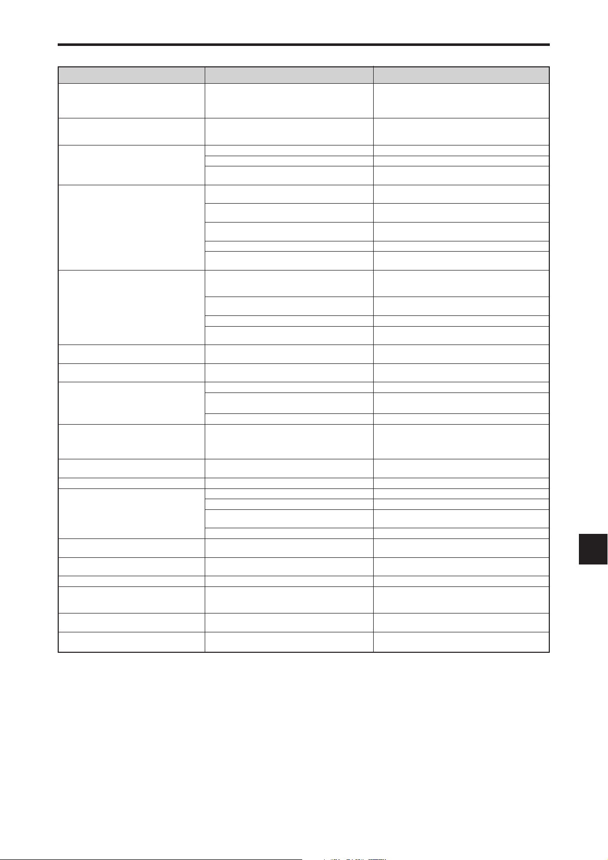
Troubleshooting
If the picture quality is poor or there is some other problem, check the adjustments, operations, etc., before requesting service.
Symptom
The unit emits a crackling sound.
Picture is disturbed.
Sound is noisy.
Remote control operates erroneously.
The remote control does not work.
Monitor’s power does not turn on when the
remote control’s power button is pressed.
Monitor does not operate when the remote
control’s buttons are pressed.
The front panel buttons of the main unit do
not function.
No sound or picture is produced.
Picture appears but no sound is produced.
Poor picture with VIDEO signal input.
Poor picture with RGB signal input.
Tint is poor or colors are weak.
Nothing appears on screen.
Part of picture is cut off or picture is not
centered.
Image is too large or too small.
Picture is unstable.
POWER/STANDBY indicator is lighted in red.
POWER/STANDBY indicator is blinking in
red.
POWER/STANDBY indicator is blinking in
green and red, or green.
Checks
• Are the image and sound normal?
• Is a connected component set directly in front or at
the side of the display?
• Are the remote control’s batteries worn out?
• Is IR REMOTE set to ON?
• Has an ID number been set for the main unit?
• Is the monitor’s power cord plugged into a power
outlet?
• Are all the monitor’s indicators off?
• Are the remote control’s batteries worn out?
• Is IR REMOTE set to OFF?
• Has an ID number been set for the main unit?
• Is the remote control pointed at the monitor, or is
there an obstacle between the remote control and
the monitor?
• Is direct sunlight or strong artificial light shining on
the monitor’s remote control sensor?
•
Are the remote control’s batteries worn out?
• The remote cable is plugged into the REMOTE IN
terminal (Wired).
• The front panel buttons do not function during
Control Lock.
• Is the monitor’s power cord plugged into a power
outlet?
• Is the volume set at the minimum?
• Is the mute mode set?
• Are the speakers properly connected?
• Is AUDIO INPUT set correctly?
• Improper control setting.
Local interference.
Cable interconnections.
Input impedance is not correct level.
• Improper control setting.
Incorrect 15 PIN connector pin connections.
• Are the tint and colors properly adjusted?
• Is the computer’s power turned on?
• Is a source connected?
• Is the power management function in the standby
or off mode?
• Is LOOP OUT set to ON?
• Is the position adjustment appropriate?
• Is the screen size adjustment appropriate?
• Is the computer’s resolution setting appropriate?
• Horizontal and / or vertical sync signal is not
present when the Intelligent Power Manager
control is on.
• The temperature inside the main unit has become
too high and has activated the protector.
——————
• If there are no abnormalities in the image and sound,
the noise is caused by the cabinet reacting to
changes in temperature. This will not affect
performance.
• Leave some space between the display and the
connected components.
• Replace both batteries with new ones.
• Set IR REMOTE OFF on OPTION3 menu.
• Set an ID number with the ID SELECT button, or set
the ID number to ALL.
• Plug the monitor’s power cord into a power outlet.
• Press the power button on the monitor to turn on the
power.
• Replace both batteries with new ones.
• Set IR REMOTE ON.
• Set an ID number with the ID SELECT button, or set
the ID number to ALL.
• Point the remote control at the monitor’s remote
control sensor when pressing buttons, or remove the
obstacle.
• Eliminate the light by closing curtains, pointing the
light in a different direction, etc.
• Replace both batteries with new ones.
• Unplug the remote cable from the monitor.
• Set the Control Lock to OFF.
• Plug the monitor’s power cord into a power outlet.
• Increase the volume.
• Press the remote control’s MUTE button.
• Connect the speakers properly.
• Set AUDIO INPUT on the AUDIO menu correctly.
• Adjust picture control as needed.
Try another location for the monitor.
Be sure all connections are secure.
• Adjust picture controls as needed.
Check pin assignments and connections.
• Adjust the tint and color (under PICTURE).
• Turn on the computer’s power.
• Connect source to the monitor.
• Operate the computer (move the mouse, etc.).
• Set LOOP OUT OFF.
• Adjust the IMAGE ADJUST properly.
• Press the WIDE button on the remote control and
adjust properly.
• Set to the proper resolution.
• Check the input signal.
• Promptly switch off the power of the main unit and
wait until the internal temperature drops. See*1.
• Prompty switch off the power of the main unit. See
*2.
Remedy
*1 Overheat protector
If the monitor becomes too hot, the overheat protector will be activated and the monitor will be turned off. If this happens, turn off the power to the monitor
and unplug the power cord. If the room where the monitor is installed is particularly hot, move the monitor to a cooler location and wait for the monitor
to cool for 60 minutes. If the problem persists, contact your dealer.
*2 In the following case, power off the monitor immediately and contact your dealer or authorized Service Center.
The monitor turns off 5 seconds after powering on and then the POWER/STANDBY indicator blinks. It indicates that the power supply circuit, plasma
display panel, temperature sensor, or one or more fans have been damaged.
En-41

Table of Signals Supported
Supported resolution (42XM5)
• When the screen mode is NORMAL, each signal is converted to a 768 dots⳯768 lines signal. (Except for *3)
• When the screen mode is FULL, each signal is converted to a 1024 dots⳯768 lines signal.
Computer input signals supported by this system
– –
– –
– –
– –
Screen mode
NORMAL
(4:3)
– –
– –
YES
YES
YES
YES
YES
YES
– –
– –
– –
YES
YES
YES
YES
YES
YES
YES
YES
YES
YES
YES
YES
YES
YES
YES
YES
– –
– –
– –
– –
– –
YES
YES
– –
– –
– –
YES*
YES*
YES*
YES*
YES
YES
YES
– –
YES
YES
YES
YES
YES
– –
– –
– –
– –
YES
YES
YES
YES
– –
Model
Signal Type
NEC PC-9800
IBM PC/AT
compatible
computers
Apple
Macintosh*
5
Dots ⳯ lines
640⳯400
720⳯400
640⳯480
720⳯400
848⳯480
852⳯480*
800⳯600
1024⳯768
1152⳯864
1280⳯768
1280⳯800*
1280⳯854
1280⳯960
1360⳯765
1360⳯768
1376⳯768
1280⳯1024
1400⳯1050*
1680⳯1050*
1600⳯1200
1920⳯1080*
1920⳯1200*
1920⳯1200RB
640⳯480
832⳯624
1024⳯768
1152⳯870
1440⳯900*
Vertical
frequency
(Hz)
1
7
7
7
8
7
7
*
7
70.1
70.1
59.9
72.8
75.0
85.0
100.4
120.4
85.1
60.0
60.0
56.3
60.3
72.2
75.0
85.1
99.8
120.0
60.0
70.1
75.0
85.0
100.6
119.4
75.0
60.0
72.0
56.2
59.8
69.8
59.8
60.0
60.0
85.0
60.0
60.0
59.9
60.0
75.0
85.0
100.1
60.0
74.9
85.0
60.0
60.0
65.0
70.0
75.0
85.0
50.0
60.0
59.9
60.0
66.7
74.6
74.9
75.1
59.9
Horizontal
frequency
(kHz)
31.5
31.5
31.5
37.9
37.5
43.3
51.1
61.3
37.9
31.0
31.7
35.2
37.9
48.1
46.9
53.7
63.0
75.7
48.4
56.5
60.0
68.7
80.5
95.5
67.5
53.7
64.9
45.1
48.0
56.0
49.7
53.1
60.0
85.9
47.7
47.7
48.3
64.0
80.0
91.1
108.5
65.3
82.3
93.9
65.3
75.0
81.3
87.5
93.8
106.3
56.2
67.5
74.6
74.0
35.0
49.7
60.2
68.7
55.9
Sync Polarity
Horizontal
NEG
NEG
NEG
NEG
NEG
NEG
NEG
NEG
NEG
POS
NEG
POS
POS
POS
POS
POS
POS
POS
NEG
NEG
POS
POS
NEG
NEG
POS
POS
POS
POS
POS
NEG
NEG
NEG
POS
POS
POS
POS
NEG
POS
POS
POS
POS
NEG
NEG
NEG
NEG
POS
POS
POS
POS
POS
POS
POS
NEG
NEG
Sync on G
Sync on G
Sync on G
Sync on G
NEG
Vertical
NEG
NEG
NEG
NEG
NEG
NEG
NEG
NEG
POS
POS
NEG
POS
POS
POS
POS
POS
POS
POS
NEG
NEG
POS
POS
NEG
NEG
POS
NEG
NEG
POS
NEG
POS
POS
NEG
POS
POS
POS
POS
POS
POS
POS
POS
POS
POS
POS
POS
POS
POS
POS
POS
POS
POS
POS
POS
POS
POS
Sync on G
Sync on G
Sync on G
Sync on G
POS
Presence
Horizontal
YES
YES
YES
YES
YES
YES
YES
YES
YES
YES
YES
YES
YES
YES
YES
YES
YES
YES
YES
YES
YES
YES
YES
YES
YES
YES
YES
YES
YES
YES
YES
YES
YES
YES
YES
YES
YES
YES
YES
YES
YES
YES
YES
YES
YES
YES
YES
YES
YES
YES
YES
YES
YES
YES
– –
– –
– –
– –
YES
Vertical
YES
YES
YES
YES
YES
YES
YES
YES
YES
YES
YES
YES
YES
YES
YES
YES
YES
YES
YES
YES
YES
YES
YES
YES
YES
YES
YES
YES
YES
YES
YES
YES
YES
YES
YES
YES
YES
YES
YES
YES
YES
YES
YES
YES
YES
YES
YES
YES
YES
YES
YES
YES
YES
YES
YES
RGB
4
FULL
select*
(16:9)
YES
YES
YES
YES
YES
YES
YES
YES
YES
YES
YES
YES
YES
YES
YES
YES
YES
YES
YES*
YES*
YES*
YES*
YES*
YES*
YES
YES
YES
YES
YES
YES
YES
YES
YES
YES
YES
YES
YES
3
YES
3
YES
3
YES
3
YES
YES
YES
YES
YES
YES
YES
YES
YES
YES
YES
YES
YES
YES
YES
YES
YES*
YES
YES
– –
720⳯400
640⳯480
– –
– –
– –
– –
– –
– –
848⳯480
852⳯480
800⳯600
– –
– –
– –
– –
– –
– –
2
1024⳯768
2
1024⳯768
2
1024⳯768
2
– –
2
– –
2
– –
1152⳯864
1152⳯864
– –
1280⳯768
1280⳯768
1280⳯768
1280⳯800
1280⳯854
– –
– –
1360⳯765
1360⳯768
1376⳯768
1280⳯1024
– –
– –
– –
1400⳯1050
– –
– –
1680⳯1050
1600⳯1200
– –
– –
– –
– –
1920⳯1080
1920⳯1080
1920⳯1200
1920⳯1200RB
– –
– –
2
– –
– –
– –
DVI
NO
YES
YES
YES
YES
YES
YES
YES
YES
YES
YES
YES
YES
YES
YES
YES
YES
YES
YES
YES
YES
YES
YES
YES
YES
YES
YES
NO
YES
YES
YES
YES
YES
YES
NO
YES
YES
YES
YES
YES
NO
YES
YES
NO
YES
YES
NO
NO
NO
NO
YES
YES
– –
YES
NO
NO
NO
NO
YES
TEXT
INSERT
YES
YES
YES
YES
YES
YES
YES
YES
YES
YES
YES
YES
YES
YES
YES
YES
YES
YES
YES
YES
YES
YES
YES*
YES*
YES
YES
YES
YES
YES
YES
YES
YES
YES
YES*
YES
YES
YES
YES
YES*
YES*
YES*
YES*
YES*
YES*
YES*
YES*
YES*
YES*
YES*
YES*
YES*
YES*
YES*
YES*
YES
YES
YES
YES
YES
9
9
9
9
9
9
9
9
9
9
9
9
9
9
9
9
9
9
9
Memory
4
82
5
7
8
9
41
42
73
19
17
11
12
13
14
15
43
44
24
25
26
27
45
46
51
84
85
52
80
66
21
37
63
64
22
22
53
29
30
40
47
131
71
72
38
54
55
56
57
58
111
110
81
88
6
16
28
39
89
En-42

Model
Signal Type
Work Station
(EWS4800)
Work Station (HP)
Work Station
(SUN)
Work Station
(SGI)
Dots ⳯ lines
1280⳯1024
1280⳯1024
1152⳯900
1280⳯1024
1024⳯768
1280⳯1024
Vertical
frequency
(Hz)
60.0
71.2
72.0
66.0
76.0
76.1
60.0
60.0
Horizontal
frequency
(kHz)
64.6
75.1
78.1
61.8
71.7
81.1
49.7
63.9
Sync Polarity
Horizontal
NEG
NEG
– –
C Sync
C Sync
C Sync
– –
– –
Vertical
NEG
NEG
– –
C Sync
C Sync
C Sync
– –
– –
Presence
Horizontal
YES
YES
– –
– –
– –
– –
– –
– –
Vertical
YES
YES
– –
– –
– –
– –
– –
– –
Screen mode
NORMAL
(4:3)
3
YES*
3
YES*
3
YES*
YES
YES
3
YES*
YES
3
YES*
FULL
(16:9)
YES
YES
YES
YES
YES
YES
YES*
YES
RGB
select*
1280⳯1024
2
1024⳯768
1280⳯1024
4
– –
– –
– –
– –
– –
IDC-3000G
PAL625P
NTSC525P
768⳯576
640⳯480
50.0
59.9
31.4
31.5
NEG
NEG
NEG
NEG
YES
YES
YES
YES
YES*
YES*
6
6
YES*
YES*
6
– –
6
525P
*1 Only when using a graphic accelerator board that is capable of displaying 852⳯480.
*2 The picture is displayed in the original resolution. The picture will be compressed for other signals.
*3 Aspect ratio is 5:4. This signal is converted to a 720 dots⳯768 lines signal.
*4 Normally the RGB select mode suite for the input signals is set automatically. If the picture is not displayed properly, set the
RGB mode prepared for the input signals listed in the table above.
*5 To connect the monitor to Macintosh computer, use the monitor adapter (D-Sub 15-pin) to your computer's video port.
*6 Other screen modes (ZOOM and STADIUM) are available as well.
*7 CVT standard compliant.
*8 Analog signal is not available.
*9 The text cannot be displayed at the “RIGHT” and “LEFT” location.
DVI
YES
YES
YES
YES
YES
YES
YES
YES
NO
NO
TEXT
INSERT
YES*
YES*
YES*
YES
YES
YES*
YES*
YES*
YES*
YES*
9
9
9
9
9
9
9
9
Memory
29
48
59
60
61
30
62
29
31
32
NOTE:
• While the input signals comply with the resolution listed in the table above, you may have to adjust the position and size of the
picture or the fine picture because of errors in synchronization of your computer.
• This monitor has a resolution of 1024 dots⳯768 lines. It is recommended that the input signal should be XGA, wide XGA, or
equivalent.
• With digital input some signals are not accepted.
• The sync may be disturbed when a nonstandard signal other than the aforementioned is input.
• If you are connecting a composite sync signal, use the HD terminal.
What is HDCP/HDCP technology?
HDCP is an acronym for High-bandwidth Digital Content Protection. High bandwidth Digital Content Protection (HDCP) is a
system for preventing illegal copying of video data sent over a Digital Visual Interface (DVI).
If you are unable to view material via the DVI input, this does not necessarily mean the PDP is not functioning properly. With
the implementation of HDCP, there may be cases in which certain content is protected with HDCP and might not be displayed
due to the decision/intention of the HDCP community (Digital Content Protection, LLC).
•“IBM PC/AT” and “XGA” are registered trademarks of International Business Machines, Inc. of the United States.
•“Apple Macintosh” is a registered trademark of Apple Computer, Inc. of the United States.
En-43

Supported resolution (50XM6/60XM5)
• When the screen mode is NORMAL, each signal is converted to a 1024 dots⳯768 lines signal. (Except for *
• When the screen mode is TRUE, the picture is displayed in the original resolution.
• When the screen mode is FULL, each signal is converted to a 1365 dots⳯768 lines signal. (Except for *
Computer input signals supported by this system
Model
Signal Type
NEC PC-9800
IBM PC/AT
compatible
computers
Apple
Macintosh*
5
Dots ⳯ lines
640⳯400
720⳯400
640⳯480
720⳯400
848⳯480
852⳯480*
800⳯600
1024⳯768
1152⳯864
1280⳯768
1280⳯800*
1280⳯854
1280⳯960
1360⳯765
1360⳯768
1376⳯768
1280⳯1024
1400⳯1050*
1680⳯1050*
1600⳯1200
1920⳯1080*
1920⳯1200*
1920⳯1200RB
640⳯480
832⳯624
1024⳯768
1152⳯870
1440⳯900*
Vertical
frequency
(Hz)
1
7
7
7
8
7
7
*
7
70.1
70.1
59.9
72.8
75.0
85.0
100.4
120.4
85.1
60.0
60.0
56.3
60.3
72.2
75.0
85.1
99.8
120.0
60.0
70.1
75.0
85.0
100.6
119.4
75.0
60.0
72.0
56.2
59.8
69.8
59.8
60.0
60.0
85.0
60.0
60.0
59.9
60.0
75.0
85.0
100.1
60.0
74.9
85.0
60.0
60.0
65.0
70.0
75.0
85.0
50.0
60.0
59.9
60.0
66.7
74.6
74.9
75.1
59.9
Horizontal
frequency
(kHz)
31.5
31.5
31.5
37.9
37.5
43.3
51.1
61.3
37.9
31.0
31.7
35.2
37.9
48.1
46.9
53.7
63.0
75.7
48.4
56.5
60.0
68.7
80.5
95.5
67.5
53.7
64.9
45.1
48.0
56.0
49.7
53.1
60.0
85.9
47.7
47.7
48.3
64.0
80.0
91.1
108.5
65.3
82.3
93.9
65.3
75.0
81.3
87.5
93.8
106.3
56.2
67.5
74.6
74.0
35.0
49.7
60.2
68.7
55.9
Sync Polarity
Horizontal
NEG
NEG
NEG
NEG
NEG
NEG
NEG
NEG
NEG
POS
NEG
POS
POS
POS
POS
POS
POS
POS
NEG
NEG
POS
POS
NEG
NEG
POS
POS
POS
POS
POS
NEG
NEG
NEG
POS
POS
POS
POS
NEG
POS
POS
POS
POS
NEG
NEG
NEG
NEG
POS
POS
POS
POS
POS
POS
POS
NEG
NEG
Sync on G
Sync on G
Sync on G
Sync on G
NEG
Vertical
NEG
NEG
NEG
NEG
NEG
NEG
NEG
NEG
POS
POS
NEG
POS
POS
POS
POS
POS
POS
POS
NEG
NEG
POS
POS
NEG
NEG
POS
NEG
NEG
POS
NEG
POS
POS
NEG
POS
POS
POS
POS
POS
POS
POS
POS
POS
POS
POS
POS
POS
POS
POS
POS
POS
POS
POS
POS
POS
POS
Sync on G
Sync on G
Sync on G
Sync on G
POS
Presence
Horizontal
YES
YES
YES
YES
YES
YES
YES
YES
YES
YES
YES
YES
YES
YES
YES
YES
YES
YES
YES
YES
YES
YES
YES
YES
YES
YES
YES
YES
YES
YES
YES
YES
YES
YES
YES
YES
YES
YES
YES
YES
YES
YES
YES
YES
YES
YES
YES
YES
YES
YES
YES
YES
YES
YES
– –
– –
– –
– –
YES
Vertical
YES
YES
YES
YES
YES
YES
YES
YES
YES
YES
YES
YES
YES
YES
YES
YES
YES
YES
YES
YES
YES
YES
YES
YES
YES
YES
YES
YES
YES
YES
YES
YES
YES
YES
YES
YES
YES
YES
YES
YES
YES
YES
YES
YES
YES
YES
YES
YES
YES
YES
YES
YES
YES
YES
– –
– –
– –
– –
YES
2
)
Screen mode
NORMAL
(4:3)
– –
– –
YES
YES
YES
YES
YES
YES
– –
– –
– –
YES
YES
YES
YES
YES
YES
YES
2
YES*
2
YES*
2
YES*
2
YES*
2
YES*
2
YES*
YES
YES
YES
– –
– –
– –
– –
– –
YES
YES
– –
– –
– –
3
YES*
3
YES*
3
YES*
3
YES*
YES
YES
YES
– –
YES
YES
YES
YES
YES
– –
– –
– –
– –
YES
YES
2
YES*
YES
– –
2, 3
)
TRUE
YES
YES
YES
YES
YES
YES
YES
YES
YES
YES
YES
YES
YES
YES
YES
YES
YES
YES
– –
– –
– –
– –
– –
– –
– –
– –
– –
– –
– –
– –
– –
– –
– –
– –
– –
– –
– –
– –
– –
– –
– –
– –
– –
– –
– –
– –
– –
– –
– –
– –
– –
– –
– –
– –
YES
YES
– –
– –
– –
FULL
(16:9)
YES
YES
YES
YES
YES
YES
YES
YES
YES
YES
YES
YES
YES
YES
YES
YES
YES
YES
YES
YES
YES
YES
YES
YES
YES
YES
YES
YES
YES
YES
YES
YES
YES
YES
YES*
YES*
YES
YES
YES
YES
YES
YES
YES
YES
YES
YES
YES
YES
YES
YES
YES
YES
YES
YES
YES
YES
YES
YES
YES
RGB
select*
– –
720⳯400
640⳯480
– –
– –
– –
– –
– –
– –
848⳯480
852⳯480
800⳯600
– –
– –
– –
– –
– –
– –
1024⳯768
1024⳯768
1024⳯768
– –
– –
– –
1152⳯864
1152⳯864
– –
1280⳯768
1280⳯768
1280⳯768
1280⳯800
1280⳯854
– –
– –
2
1360⳯765
2
1360⳯768
1376⳯768
1280⳯1024
– –
– –
– –
1400⳯1050
– –
– –
1680⳯1050
1600⳯1200
– –
– –
– –
– –
1920⳯1080
1920⳯1080
1920⳯1200
1920⳯1200RB
– –
– –
– –
– –
– –
DVI
NO
YES
YES
YES
YES
YES
YES
YES
YES
YES
YES
YES
YES
YES
YES
YES
YES
YES
YES
YES
YES
YES
YES
YES
YES
YES
YES
NO
YES
YES
YES
YES
YES
YES
NO
YES
YES
YES
YES
YES
NO
YES
YES
NO
YES
YES
NO
NO
NO
NO
YES
YES
– –
YES
NO
NO
NO
NO
YES
TEXT
INSERT
YES
YES
YES
YES
YES
YES
YES
YES
YES
YES
YES
YES
YES
YES
YES
YES
YES
YES
YES
YES
YES
YES
YES*
YES*
YES
YES
YES
YES
YES
YES
YES
YES
YES
YES*
YES
YES
YES
YES
YES*
YES*
YES*
YES*
YES*
YES*
YES*
YES*
YES*
YES*
YES*
YES*
YES*
YES*
YES*
YES*
YES
YES
YES
YES
YES
9
9
9
9
9
9
9
9
9
9
9
9
9
9
9
9
9
9
9
Memory
4
82
5
7
8
9
41
42
73
19
17
11
12
13
14
15
43
44
24
25
26
27
45
46
51
84
85
52
80
66
21
37
63
64
22
22
53
29
30
40
47
131
71
72
38
54
55
56
57
58
111
110
81
88
6
16
28
39
89
4
En-44

Model
Signal Type
Work Station
(EWS4800)
Work Station (HP)
Work Station
(SUN)
Work Station
(SGI)
IDC-3000G
PAL625P
NTSC525P
*1 Only when using a graphic accelerator board that is capable of displaying 852⳯480.
*2 The picture is displayed in the original resolution.
*3 The aspect ratio is 5:4. This signal is converted to a 960 dots⳯768 lines signal.
*4 Normally the RGB select mode suite for the input signals is set automatically. If the picture is not displayed properly, set the
RGB mode prepared for the input signals listed in the table above.
*5 To connect the monitor to Macintosh computer, use the monitor adapter (D-Sub 15-pin) to your computer's video port.
*6 Other screen modes (ZOOM and STADIUM) are available as well.
*7 CVT standard compliant.
*8 Analog signal is not available.
*9 The text cannot be displayed at the “RIGHT” and “LEFT” location.
Dots ⳯ lines
1280⳯1024
1280⳯1024
1152⳯900
1280⳯1024
1024⳯768
1280⳯1024
768⳯576
640⳯480
Vertical
frequency
(Hz)
60.0
71.2
72.0
66.0
76.0
76.1
60.0
60.0
50.0
59.9
Horizontal
frequency
(kHz)
64.6
75.1
78.1
61.8
71.7
81.1
49.7
63.9
31.4
31.5
Sync Polarity
Horizontal
NEG
NEG
– –
C Sync
C Sync
C Sync
– –
– –
NEG
NEG
Vertical
NEG
NEG
– –
C Sync
C Sync
C Sync
– –
– –
NEG
NEG
Presence
Horizontal
YES
YES
– –
– –
– –
– –
– –
– –
YES
YES
Vertical
YES
YES
– –
– –
– –
– –
– –
– –
YES
YES
Screen mode
NORMAL
(4:3)
3
YES*
3
YES*
3
YES*
YES
YES
3
YES*
2
YES*
3
YES*
6
YES*
6
YES*
TRUE
– –
– –
– –
– –
– –
– –
– –
– –
– –
– –
FULL
(16:9)
YES
YES
YES
YES
YES
YES
YES
YES
YES*
YES*
RGB
select*
1280⳯1024
1024⳯768
1280⳯1024
6
6
525P
– –
– –
– –
– –
– –
– –
DVI
YES
YES
YES
YES
YES
YES
YES
YES
NO
NO
TEXT
INSERT
YES*
YES*
YES*
YES
YES
YES*
YES*
YES*
YES*
YES*
9
9
9
9
9
9
9
9
Memory
29
48
59
60
61
30
62
29
31
32
4
NOTE:
• While the input signals comply with the resolution listed in the table above, you may have to adjust the position and size of the
picture or the fine picture because of errors in synchronization of your computer.
• When a 1280 dots⳯1024 lines signal or 1600 dots⳯1200 lines signal is input to the monitor, the picture will be compressed.
• This monitor has a resolution of 1365 dots
⳯
768 lines. It is recommended that the input signal should be XGA, wide XGA, or
equivalent.
• With digital input some signals are not accepted.
• The sync may be disturbed when a nonstandard signal other than the aforementioned is input.
• If you are connecting a composite sync signal, use the HD terminal.
What is HDCP/HDCP technology?
HDCP is an acronym for High-bandwidth Digital Content Protection. High bandwidth Digital Content Protection (HDCP) is a
system for preventing illegal copying of video data sent over a Digital Visual Interface (DVI).
If you are unable to view material via the DVI input, this does not necessarily mean the PDP is not functioning properly. With
the implementation of HDCP, there may be cases in which certain content is protected with HDCP and might not be displayed
due to the decision/intention of the HDCP community (Digital Content Protection, LLC).
•“IBM PC/AT” and “XGA” are registered trademarks of International Business Machines, Inc. of the United States.
•“Apple Macintosh” is a registered trademark of Apple Computer, Inc. of the United States.
En-45

Specifications
䡵 42XM5
Screen Size 36.3 inches(H)⳯20.3 inches(V)
921.6 mm(H)⳯515.3 mm(V)
diagonal 42 inches
Aspect Ratio 16 : 9
Resolution 1024 pixels(H)⳯768 pixels(V)
Pixel Pitch 0.036 inches(H)⳯0.027 inches(V)
0.9 mm(H)⳯0.671 mm(V)
Signals
Synchronization Range Horizontal : 15.5 kHz to 110.0 kHz
Input Signals RGB, NTSC (3.58/4.43), PAL (B,G,M,N),
Input Terminals (VIDEO1 and RGB1 can also be used as OUTPUT terminals)
RGB
Visual 1 (Analog) mini D-sub 15-pin⳯1
Visual 2 (Analog) BNC (R, G, B, HD, DV)⳯1*
Visual 3 (Digital) DVI-D 24-pin⳯1*
Video
Visual 1 BNC⳯1
Visual 2 RCA-pin⳯1
Visual 3 S-Video: DIN 4-pin⳯1
DVD/HD
Visual 1 RCA-pin (Y, Cb/Pb, Cr/Pr)⳯1*
Visual 2 BNC (Y, Cb/Pb, Cr/Pr)⳯1*
Visual 3 DVI-D 24-pin⳯1*
Audio Stereo RCA⳯3(Selectable)
External Control D-sub 9-pin⳯1(RS-232C)
Remote In Mini jack⳯1
Remote Out Mini jack⳯1
Sound output 8 W+8 W at 6 ohm
Power Supply AC100 V to 240 V 50 Hz/60 Hz
Current Rating 4.5 A (maximum)
Power Consumption 285 W (typical)
Dimensions 40.2 inches(W)⳯24 inches(H)⳯3.9 inches(D)
1022 mm(W)⳯610 mm(H)⳯98 mm(D)
Weight 66.1 lbs / 30 kg (without stand)
Environmental Considerations
Operating Temperature 0 °C to 40 °C / 32 °F to 104 °F
Humidity 20 % to 80 % (no condensation)
Storage Temperature -10 °C to 50 °C / 14 °F to 122 °F
Humidity 10 % to 90 % (no condensation)
Other Features Motion compensated 3D Scan Converter (NTSC,
Accessories Power cord (⳯1), Remote control (⳯1), AAA
Regulations UL 60950-1, CAN/CSA-C22.2 No.60950-1-03,
(automatic : step scan)
Vertical : 50.0 Hz to 120.0 Hz
(automatic : step scan)
PAL60, SECAM, HD*
1
, DVD*1 , DTV*
3
3
2
1, *2
1
PAL, 480I, 576I, 525I, 625I, 1035I, 1080I), 2-3
pull down Converter (NTSC, 480I, 525I, 1035I,
1080I (60 Hz)), 2-2 pull down Converter (PAL,
576I, 625I, NTSC, 480I, 525I), Digital Zooming
(100 % to 900 % Selectable), Video Wall 4-25
multi screens, Self Diagnosis via RS232C,
Long Life Mode (PEAK BRIGHT, ORBITER,
INVERSE, WHITE, SCREEN WIPER, SOFT
FOCUS, etc.), Control Lock (Except power SW),
Input Skip, Color Tune, Programmable Timer,
Loop Throughout Interface, Plug and play
(DDC1, DDC2b, RGB3: DDC2b only), Enhanced
Split Screen, Protocol Set, etc.
batteries (⳯2), Manuals (Start up Guide and
CD-ROM), Ferrite cores for power cord (⳯2),
bands for power code (⳯2), Cable clampers
(⳯3), beads bands (⳯3), Ferrite core for
remote cable (⳯2).
FCC class B, ICES-003 class B
1.59"
40.2" (1022)
36.3" (921.6)
20.3" (515.3)
1
(40.4)
24" (610)
Units are in inch
(98)
3.9"
2.31"
(57.6)
(mm)
The features and specifications may be subject to change without
notice.
*1HD/DVD/DTV input signals supported on this system.
480P (60 Hz) 480I (60 Hz) 525P (60 Hz)
525I (60 Hz) 576P (50 Hz) 576I (50 Hz)
625P (50 Hz) 625I (50 Hz) 720P (60 Hz)
720P (50 Hz) 1035I (60 Hz) 1080I (50 Hz)
1080I (60 Hz) 1080P (50 Hz) 1080P (60 Hz)
2
*
The 5-BNC connectors are used as RGB2 and DVD/HD2 input.
Select one of them under “BNC INPUT”.
3
*
Compatible with HDCP.
Supported Signals
• 640ⴒ480P @ 59.94/60 Hz • 1440 (720)ⴒ480I @ 59.94/60 Hz
• 720ⴒ480P @ 59.94/60 Hz • 1440 (720)ⴒ576I @ 50 Hz
• 720ⴒ576P @ 50 Hz • 1920ⴒ1080I @ 59.94/60 Hz
• 1280ⴒ720P @ 59.94/60 Hz • 1920ⴒ1080I @ 50 Hz
• 1280ⴒ720P @ 50 Hz
• 1920ⴒ1080P @ 59.94/60 Hz
• 1920ⴒ1080P @ 50 Hz
Note: In some cases a signal on the plasma monitor may not be displayed
properly. The problem may be an inconsistency with standards from
the source equipment (DVD, Set-top box, etc.). If you do experience
such a problem please contact NEC Corporation of America and also
the manufacturer of the source equipment.
En-46

Specifications
䡵 50XM6
Screen Size 43.4 inches(H)⳯24.4 inches(V)
1104 mm(H)⳯621 mm(V)
diagonal 50 inches
Aspect Ratio 16 : 9
Resolution 1365 pixels(H)⳯768 pixels(V)
Pixel Pitch 0.032 inches(H)⳯0.032 inches(V)
0.81 mm(H)⳯0.81 mm(V)
Signals
Synchronization Range Horizontal : 15.5 kHz to 110.0 kHz
Input Signals RGB, NTSC (3.58/4.43), PAL (B,G,M,N),
Input Terminals (VIDEO1 and RGB1 can also be used as OUTPUT terminals)
RGB
Visual 1 (Analog) mini D-sub 15-pin⳯1
Visual 2 (Analog) BNC (R, G, B, HD, VD)⳯1*
Visual 3 (Digital) DVI-D 24-pin⳯1*
Video
Visual 1 BNC⳯1
Visual 2 RCA-pin⳯1
Visual 3 S-Video: DIN 4-pin⳯1
DVD/HD
Visual 1 RCA-pin (Y, Cb/Pb, Cr/Pr)⳯1*
Visual 2 BNC (Y, Cb/Pb, Cr/Pr)⳯1*
Visual 3 DVI-D 24-pin⳯1*
Audio Stereo RCA⳯3 (Selectable)
External Control D-sub 9-pin⳯1 (RS-232C)
Remote In Mini jack⳯1
Remote Out Mini jack⳯1
Sound output 9 W+9 W at 6 ohm
Power Supply AC100 V to 240 V 50 Hz/60 Hz
Current Rating 5.0 A (maximum)
Power Consumption 340 W (typical)
Dimensions 48.1 inches(W)⳯29.0 inches(H)⳯3.9 inches(D)
1222 mm(W)⳯736 mm(H)⳯99 mm(D)
Weight 91.4 lbs / 41.5 kg (without stand)
Environmental Considerations
Operating Temperature 0 °C to 40 °C / 32 °F to 104 °F
Humidity 20 % to 80 % (no condensation)
Storage Temperature -10 °C to 50 °C / 14 °F to 122 °F
Humidity 10 % to 90 % (no condensation)
Other Features Motion compensated 3D Scan Converter (NTSC,
Accessories Power cord (⳯1), Remote control (⳯1), AAA
Regulations UL 60950-1, CAN/CSA-C22.2 No.60950-1-03,
(automatic : step scan)
Vertical : 50.0 Hz to 120.0 Hz
(automatic : step scan)
PAL60, SECAM, HD*1 , DVD*1 , DTV*1
2
3
1
1, *2
3
PAL, 480I, 576I, 525I, 625I, 1035I, 1080I), 2-3
pull down Converter (NTSC, 480I, 525I, 1035I,
1080I (60 Hz)), 2-2 pull down Converter (PAL,
576I, 625I, NTSC, 480I, 525I), Digital Zooming
(100 % to 900 % Selectable), Video Wall 4-25
multi screens, Self Diagnosis via RS232C,
Long Life Mode (PEAK BRIGHT, ORBITER,
INVERSE, WHITE, SCREEN WIPER, SOFT
FOCUS, etc.), Control Lock (Except power SW),
Input Skip, Color Tune, Programmable Timer,
Loop Throughout Interface, Plug and play
(DDC1, DDC2b, RGB3: DDC2b only), Enhanced
Split Screen, Protocol Set, etc.
batteries (⳯2), Manuals (Start up Guide and
CD-ROM), Ferrite cores for power cord (⳯2),
bands for power code (⳯2), Cable clampers
(⳯3), beads bands (⳯3), Ferrite core for
remote cable (⳯2).
FCC class B, ICES-003 class B
1.5"
3.9"
(99)
2.4"
(61)
(mm)
48.1" (1222)
43.4" (1104)
24.4" (621)
(38)
29" (736)
Units are in inch
The features and specifications may be subject to change without
notice.
*1HD/DVD/DTV input signals supported on this system.
480P (60 Hz) 480I (60 Hz) 525P (60 Hz)
525I (60 Hz) 576P (50 Hz) 576I (50 Hz)
625P (50 Hz) 625I (50 Hz) 720P (60 Hz)
720P (50 Hz) 1035I (60 Hz) 1080I (50 Hz)
1080I (60 Hz) 1080P (50 Hz) 1080P (60 Hz)
2
*
The 5-BNC connectors are used as RGB2 and DVD/HD2 input.
Select one of them under “BNC INPUT”.
3
*
Compatible with HDCP.
Supported Signals
• 640ⴒ480P @ 59.94/60 Hz • 1440 (720)ⴒ480I @ 59.94/60 Hz
• 720ⴒ480P @ 59.94/60 Hz • 1440 (720)ⴒ576I @ 50 Hz
• 720ⴒ576P @ 50 Hz • 1920ⴒ1080I @ 59.94/60 Hz
• 1280ⴒ720P @ 59.94/60 Hz • 1920ⴒ1080I @ 50 Hz
• 1280ⴒ720P @ 50 Hz
• 1920ⴒ1080P @ 59.94/60 Hz
• 1920ⴒ1080P @ 50 Hz
Note: In some cases a signal on the plasma monitor may not be displayed
properly. The problem may be an inconsistency with standards from
the source equipment (DVD, Set-top box, etc.). If you do experience
such a problem please contact NEC Corporation of America and also
the manufacturer of the source equipment.
En-47
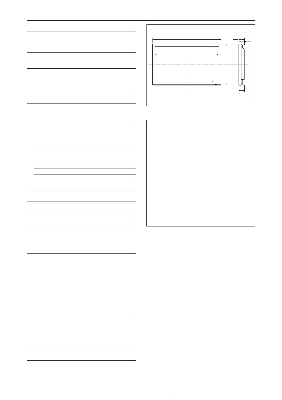
Specifications
䡵 60XM5
Screen Size 51.9 inches(H)⳯29.2 inches(V)
1319 mm(H)⳯742 mm(V)
diagonal 60 inches
Aspect Ratio 16 : 9
Resolution 1365 pixels(H)⳯768 pixels(V)
Pixel Pitch 0.038 inches(H)⳯0.038 inches(V)
0.97 mm(H)⳯0.97 mm(V)
Signals
Synchronization Range Horizontal : 15.5 kHz to 110.0 kHz
Input Signals RGB, NTSC (3.58/4.43), PAL (B,G,M,N),
Input Terminals (VIDEO1 and RGB1 can also be used as OUTPUT terminals)
RGB
Visual 1 (Analog) mini D-sub 15-pin⳯1
Visual 2 (Analog) BNC (R, G, B, HD, VD)⳯1*
Visual 3 (Digital) DVI-D 24-pin⳯1*
Video
Visual 1 BNC⳯1
Visual 2 RCA-pin⳯1
Visual 3 S-Video: DIN 4-pin⳯1
DVD/HD
Visual 1 RCA-pin (Y, Cb/Pb, Cr/Pr)⳯1*
Visual 2 BNC (Y, Cb/Pb, Cr/Pr)⳯1*
Visual 3 DVI-D 24-pin⳯1*
Audio Stereo RCA⳯3 (Selectable)
External Control D-sub 9-pin⳯1 (RS-232C)
Remote In Mini jack⳯1
Remote Out Mini jack⳯1
Sound output 9 W+9 W at 6 ohm
Power Supply AC100 V to 240 V 50 Hz/60 Hz
Current Rating 7.0 A (maximum)
Power Consumption 440 W (typical)
Dimensions 57.9 inches(W)⳯34.7 inches(H)⳯4.8 inches(D)
1470 mm(W)⳯880 mm(H)⳯122 mm(D)
Weight 135.6 lbs / 61.5 kg (without stand)
Environmental Considerations
Operating Temperature 0 °C to 40 °C / 32 °F to 104 °F
Humidity 20 % to 80 % (no condensation)
Storage Temperature -10 °C to 50 °C / 14 °F to 122 °F
Humidity 10 % to 90 % (no condensation)
Other Features Motion compensated 3D Scan Converter (NTSC,
Accessories Power cord (⳯1), Remote control (⳯1), AAA
Regulations UL 60950-1, CAN/CSA-C22.2 No.60950-1-03,
(automatic : step scan)
Vertical : 50.0 Hz to 120.0 Hz
(automatic : step scan)
PAL60, SECAM, HD*
1
, DVD*1 , DTV*
3
3
2
1, *2
1
PAL, 480I, 576I, 525I, 625I, 1035I, 1080I), 2-3
pull down Converter (NTSC, 480I, 525I, 1035I,
1080I (60 Hz)), 2-2 pull down Converter (PAL,
576I, 625I, NTSC, 480I, 525I), Digital Zooming
(100 % to 900 % Selectable), Video Wall 4-25
multi screens, Self Diagnosis via RS232C,
Long Life Mode (PEAK BRIGHT, ORBITER,
INVERSE, WHITE, SCREEN WIPER, SOFT
FOCUS, etc.), Control Lock (Except power SW),
Input Skip, Color Tune, Programmable Timer,
Loop Throughout Interface, Plug and play
(DDC1, DDC2b, RGB3: DDC2b only), Enhanced
Split Screen, Protocol Set, etc.
batteries (⳯2), Manuals (Start up Guide and
CD-ROM), Ferrite cores for power cord (⳯2),
bands for power code (⳯2), Cable clampers
(⳯3), beads bands (⳯3), Ferrite core for
remote cable (⳯2).
FCC class B, ICES-003 class B
1.8"
57.9" (1470)
51.9" (1319)
29.2" (742)
1
(45)
34.7" (880)
Units are in inch
4.8"
(122)
3.0"
(77)
(mm)
The features and specifications may be subject to change without
notice.
*1HD/DVD/DTV input signals supported on this system.
480P (60 Hz) 480I (60 Hz) 525P (60 Hz)
525I (60 Hz) 576P (50 Hz) 576I (50 Hz)
625P (50 Hz) 625I (50 Hz) 720P (60 Hz)
720P (50 Hz) 1035I (60 Hz) 1080I (50 Hz)
1080I (60 Hz) 1080P (50 Hz) 1080P (60 Hz)
2
*
The 5-BNC connectors are used as RGB2 and DVD/HD2 input.
Select one of them under “BNC INPUT”.
3
*
Compatible with HDCP.
Supported Signals
• 640ⴒ480P @ 59.94/60 Hz • 1440 (720)ⴒ480I @ 59.94/60 Hz
• 720ⴒ480P @ 59.94/60 Hz • 1440 (720)ⴒ576I @ 50 Hz
• 720ⴒ576P @ 50 Hz • 1920ⴒ1080I @ 59.94/60 Hz
• 1280ⴒ720P @ 59.94/60 Hz • 1920ⴒ1080I @ 50 Hz
• 1280ⴒ720P @ 50 Hz
• 1920ⴒ1080P @ 59.94/60 Hz
• 1920ⴒ1080P @ 50 Hz
Note: In some cases a signal on the plasma monitor may not be displayed
properly. The problem may be an inconsistency with standards from
the source equipment (DVD, Set-top box, etc.). If you do experience
such a problem please contact NEC Corporation of America and also
the manufacturer of the source equipment.
En-48

Limited Warranty Plasma Monitors
NEC Corporation of America warrants this product to be
free from defects in material and workmanship under the
following terms and, subject to the conditions set forth
below, agrees to repair or replace (at NEC Corporation of
America’ sole option) any part of the enclosed unit which
proves defective. Replacement parts or products may be
new or refurbished and will meet specifications of the
original parts or products.
HOW LONG IS THE WARRANTY?
Parts and labor are warranted for (1) one year from the
date of the first customer purchase.
WHO IS PROTECTED?
This warranty may be enforced only by the first purchaser.
WHAT IS COVERED AND WHAT IS NOT COVERED
Except as specified below, this warranty covers all defects
in material or workmanship in this product. The following
are not covered by the warranty:
1. Any product which is not distributed in the U.S.A. or Canada by
NEC Corporation of America or which is not purchased in the
U.S.A. or Canada from an authorized NEC Corporation of
America dealer.
2. Any product of which the serial number has been defaced,
modified or removed.
3. Damage, deterioration or malfunction resulting from:
a. Accident, misuse, abuse, neglect, fire, water, lightning or other
acts of nature, unauthorized product modification, or failure
to follow instructions supplied with the product.
b. Repair or attempted repair by anyone not authorized by NEC
Corporation of America.
c. Any shipment of the product (claims must be presented to the
carrier).
d. Removal or installation of the product.
e. Any other cause which does not relate to a product defect.
f. Burns or residual images upon the phosphor of the panel.
4. Cartons, carrying cases, batteries, external cabinets, magnetic
tapes, or any accessories used in connection with the product.
5. Service outside of the U.S.A. and Canada.
WHAT WE WILL PAY FOR AND WHAT WE WILL
NOT PAY FOR
We will pay labor and material expenses for covered items,
but we will not pay for the following:
1. Removal or installation charges.
2. Costs of initial technical adjustments (set-up), including
adjustment of user controls. These costs are the responsibility of
the NEC Corporation of America dealer from whom the product
was purchased.
3. Shipping charges.
HOW YOU CAN GET WARRANTY SERVICE
1. To obtain service on your product, consult the dealer from whom
you purchased the product.
2. Whenever warranty service is required, the original dated invoice
(or a copy) must be presented as proof of warranty coverage.
Please also include in any mailing your name, address and a
description of the problem(s).
3. For the name of the nearest NEC Corporation of America
authorized service center, call NEC Corporation of America at
800-836-0655.
LIMITATIONS OF LIABILITY
Except for the obligations specifically set forth in this
warranty statement, we will not be liable for any direct,
indirect, special, incidental, consequential, or other types
of damages, whether based on contract, tort, or any other
legal theory, whether or not we have been advised of the
possibility of such damages. This warranty is in lieu of all
other warranties expressed or implied, including, but not
limited to, the implied warranties of merchantability or
fitness for a particular purpose.
EXCLUSION OF DAMAGES
NEC Corporation of America’ liability for any defective
product is limited to the repair or replacement of the
product at our option. NEC Corporation of America shall
not be liable for:
1. Damage to other property caused by any defects in this
product, damages based upon inconvenience, loss of use of
the product, loss of time, commercial loss; or
2. Any other damages whether incidental, consequential or
otherwise. Some states do not allow limitation on how long
an implied warranty lasts and/or do not allow the exclusion
or limitation of incidental or consequential damages, so the
above limitations and exclusions may not apply to you.
HOW STATE LAW RELATES TO THE WARRANTY
This warranty gives you specific legal rights, and you may
also have other rights which vary from state to state.
FOR MORE INFORMATION,
TELEPHONE 800-836-0655
NEC CORPORATION OF AMERICA
1250 N. Arlington Heights Road, Suite 400
Itasca, Illinois 60143-1248
Note:
All products returned to NEC Corporation of
America for service MUST have prior approval. To get
approval, call NEC Corporation of America at 800-836-
0655.
En-49

Manuel d’utilisation
(Modèle à découpe d’image
avancée)
FRANÇAIS

Recommandations importantes
Précaution
Veuillez lire avec attention ce manuel avant d’utiliser le moniteur à plasma
et le conserver accessible pour s’y référer ultérieurement.
ATTENTION..
RISQUE D’ELECTROCUTION
NE PAS OUVRIR
ATTENTION:
POUR EVITER TOUT RISQUE D’ELECTROCUTION,
NE PAS OUVRIR LE BOITIER. A L’INTERIEUR,
AUCUNE PIECE NE NECESSITE L’INTER-VENTION
DE L’UTILISATEUR. EN CAS DE PROBLEME,
S’ADRESSER A UN REPARATEUR SPECIALISTE.
Ce symbole est une mise en garde contre les risques
d’électrocution que présentent certaines parties
dépourvues d’isolation à l’intérieur de l’appareil. Il est
donc dangereux d’établir le moindre contact avec ces
parties.
Ce symbole avertit l’utilisateur que d’importantes
informations sont fournies sur le fonctionnement ou
l’entretien de cet appareil. De ce fait, il faut lire
attentivement ces instruc-tions pour éviter tout problèm.
AVERTISSEMENT
AFIN D’EVITER TOUT RISQUE D’INCENDIE OU
D’ELECTROCUTION, NE PAS EXPOSER CET APPAREIL A LA
PLUIE OU A L’HUMIDITE. NE PAS BRANCHER LA PRISE
D’ALIMENTATION POLARISEE DANS UNE PRISE MURALE
AVEC UNE RALLONGE OU UN ADAPTATEUR MULTIPRISE
SI LES FICHES NE PEUVENT ETRE INSEREES
COMPLETEMENT. EVITER D’OUVRIR LE BOITIER CAR
CELUI-CI PROTEGE DES COMPOSANTS FONCTIONNANT
A HAUTE TENSION. EN CAS DE PROBLEME, S’ADRESSER
A UN REPARATEUR SPECIALISTE.
Avertissements et précautions de
sécurité
Ce moniteur à plasma a été conçu et fabriqu pour une utilisation
fiable et durable. Il ne nécessite aucun entretien en dehors du
nettoyage. Voir la section “Méthode de nettoyage du moniteur à
plasma” plus loin.
Le panneau à affichage plasma est constitué de fines particules
d’images (cellules) dont plus de 99,99 % sont actives. Certaines
d’entre elles ne produisent pas de lumière ou restent allumées.
Pour des raisons de sécurité et pour éviter d’endommager l’appareil,
lire attentivement les instructions suivantes.
Pour éviter les risques d’éléctrocution et d’incendie:
1.
Laisser suffisamment d’espace autour de l’appareil pour la ventilation et
éviter toute augmentation excessive de la température interne. Ne pas couvrir
les fentes d’aération ou installer l’appareil dans un endroit trop exigu.
Si vous installez l’appareil dans un espace clos, assurezvous qu’il y ait
suffisamment d’espace au dessus pour permettre l’air chaud de s’élever
et de s’évacuer.
Si la température du moniteur devient excessive, la protection contre
les surchauffes entrera en action et coupera l’alimentation. Dans ce cas,
éteindre l’appareil et débrancher le câble d’alimentation. Si la
température de la pièce dans laquelle se trouve le moniteur est
particulièrement élevée, déplacer celui-ci dans un endroit plus frais et
attendre environ 60 minutes qu’il refroidisse. Si le problème persiste,
prendre contact avec votre revendeur.
2. Ne pas raccorder la prise d’alimentation polarisée de ce périphérique à
une rallonge ou une prise murale si les fiches ne peuvent pas être
complètement insérées.
3. Ne pas exposer cet appareil à la pluie ou à l’humidité.
4. Eviter d’endommager le câble d’alimentation et ne pas le modifier.
5. Débrancher le câble d’alimentation électrique pendant les orages ou les
longues périodes d’inactivité.
6. Ne pas ouvrir le boîtier protégeant les parties dangereuses fonctionnant
hauts voltages. Si l’appareil est endommagé de cette manière, la garantie
sera annulée. De plus, les risques d’électrocution grave sont grands.
7. Ne pas essayer d’intervenir ou de réparer l’appareil. Le fabricant décline
toute responsabilité en cas de blessure corporelle ou de dégâts matériels
résultant d’une opération d’entretien quelconque effectuée par des
personnes non qualifiées ou résultant de l’ouverture du couvercle arrière.
S’adresser au service après-vente autorisé.
8. Cet équipement doit être connecté à une prise secteur (MAIN) équipée
d’une mise à la terre.
9. La prise secteur doit se trouver près de l’équipement et doit être facile
d’accès.
Pour éviter tout dommage et assurer une utilisation durable:
1.
Utiliser seulement une alimentation en courant de 100 V à 240 V 50 Hz/60 Hz.
Toute utilisation prolongée avec un courant supérieur à 100 V à 240 V risque
de diminuer la durée de vie de l’appareil et même de provoquer un incendie.
2. Manipuler l’appareil avec précautions lors de son installation, ne pas le
laisser tomber.
3. L’installer loin de toute source de chaleur ou de poussière. Ne pas
l’exposer au soleil.
4.
Eviter la pénétration de liquides ou petits objets métalliques l’intérieur de
l’appareil. En cas d’incident de ce genre, débrancher le câble d’alimentation
électrique et confier le moniteur à un service après-vente agréé.
5. Ne pas cogner ou rayer la surface de l’écran, des déformations de l’image
en résulteraient.
6. Pour un montage et une installation correcte, il est fortement
recommandé de faire appel à un revendeur agréé et qualifié.
7. Comme c’est le cas pour tout affichage à base de phosphore (comme
un moniteur CRT, par exemple), la puissance de lumière baisse
graduellement au cours de la vie du panneau d’affichage à plasma.
8. Pour éviter tout risque de sulfuration, il est fortement conseillé de ne
pas installer l’appareil dans un vestiaire, un bain public ou un bain de
source thermale.
9. Ne pas utiliser dans un véhicule en marche car l’unité pourrait tomber
ou glisser et provoquer des blessures.
10. Pour éviter l ‘inflammation ou les chocs électriques, ne pas placer l’unité
sur la tranche, à l’envers ou avec l’écran vers le bas ou vers le haut.
11. Pour éviter les risques d’incendie, ne placez aucune flamme nue (telle
qu’une bougie allumée) sur l’appareil.
Méthode de nettoyage du moniteur à plasma:
1. Nettoyer le panneau avant et le cadre en procédant à l’aide d’un chiffon
doux et sec. Ne jamais utiliser de solvents du type alcool ou diluant
pour le nettoyage de ces surfaces.
2. Nettoyer les prises d’aération du plasma en procédant à l’aide d’une
brosse à poils doux fixée à un aspirateur.
3.
Pour garantir la bonne ventilation du moniteur, nettoyer les prises d’air
tous les mois. Un nettoyage plus fréquent peut s’avérer nécessaire selon
les conditions environnantes dans lesquelles le moniteur à plasma est utilisé.
Pour éviter les risques de brûlage du luminophore, les mesures
suivantes sont recommandées:
Comme tous les périphériques d’affichage à base luminophore et tous les
autres affichages gaz plasma, les moniteurs plasma peuvent être sujets au
brûlage du luminophore dans certaines circonstances. Certaines conditions
d’utilisation, telles que l’affichage continu d’une image statique pour une
durée prolongée, peuvent causer le brûlage du luminophore si aucune
précaution n’est prise. Pour protéger votre investissement dans ce moniteur
à plasma, veuillez suivre les directives et les conseils suivantes pour
minimiser l’occurence le marquage de l’écran:
* S’assurer de mettre en marche et d’utiliser l’économiseur d’écran chaque
fois que c’est possible, pendant l’utilisation avec une source d’entrée
venant d’ un ordinateur.
* Afficher une image en mouvement aussi souvent que possible.
* Changer la position de l’affichage de menu de temps à autre.
* Toujours couper l’alimentation après la fin de l’utilisation du moniteur.
Si le moniteur à plasma est en usage continu ou de longue durée, prendre
les mesures suivantes afin d’éviter l’occurence le brûlage du luminophore:
* Abaisser le niveau de l’image (contraste, luminance) autant que possible,
sans faire perdre la lisibilit de l’image.
* Afficher une image avec de nombreuses couleurs et graduations de
couleur (par ex. des images photo-graphiques ou photo-réalistes).
*
Créer un contenu d’image avec un contraste minimal entre les zones sombres
et les zones claires, par exemple des caractères blancs sur un fond noir.
Utiliser des couleurs complémentaires ou pastels le plus souvent possible.
* Eviter d’afficher des images avec peu de couleurs et des limites nettes et
clairement définies entre les couleurs.
Son de fonctionnement du moniteur plasma
Le panneau du moniteur plasma est composé de pixels extrêmement fins et
ces pixels émettent de la lumière en fonction des signaux vidéo reçus. Ce
principe peut créer un bourdonnement ou un ronflement électrique venant
du moniteur plasma. Veuillez également noter que la vitesse de rotation du
ventilateur de refroidissement peut augmenter lorsque la température
ambiante du moniteur plasma augmente. Lorsque cela se produit, il est
possible que vous entendiez le moteur du ventilateur.
Remarque:
Les éléments suivants ne sont pas couverts par la garantie.
• Rémanence
• Sons générés par le panneau, par exemple : Bruit du moteur de
ventilateur, ronflement du circuit électrique / bourdonnement du
panneau de verre.
Contactez un revendeur agréé ou un revendeur de marque pour d'autres
Fr-2
procédures qui conviendront le mieux à vos besoins particuliers.

Avertissement
Ne pas utiliser dans une salle d’ordinateurs telle que
définie dans la Norme pour la protection des
ordinateurs électroniques/appareils de traitement des
données ANSI/NFPA75.
Cet appareil a été testé est trouvé conforme avec
les limites des appareils numériques de classe B,
conformément à l’article 15 du règlement FCC. Ces
limites sont conçues pour offrir une protection
raisonnable contre les interférences nuisibles dans
une installation résidentielle. Cet appareil génère,
utilise et peut émettre de l’énergie radiofréquence
et, s’il n’est pas installé et utilisé selon les instructions,
peut causer des interférences nuisibles aux
communications radio. Cependant, il n’y a aucune
garantie que de telles interférences ne se produisent
pas pour une installation particulière. Si cet appareil
causait des interférences nuisibles à la réception
radio ou télévisée, ce qui peut être déterminé en
mettant l’appareil hors et sous tension, vous être
encouragé à essayer de corriger ces interférences à
l’aide de l’une ou plusieurs mesures suivantes:
• Réorientez ou déplacez l’antenne réceptrice.
• Augmentez l’espace entre l’appareil est le récepteur.
• Connectez l’appareil sur une prise secteur
appartenant à un circuit différent de celui sur lequel
le récepteur est connecté.
• Consultez votre revendeur ou un technicien radio/
télévision expérimenté.
Cet appareil numérique de la classe B est conforme
à la norme NMB-003 du Canada.
REMARQUE :
Lorsque vous utilisez un câble RGB (non fourni), utilisez
un câble RGB comprenant une âme en ferrite (non fourni)
à ses deux extrémités. Sinon, ce moniteur ne sera pas
conforme aux normes FCC obligatoires.
REMARQUE :
Lorsque vous utilisez le câble d’alimentation (fourni)
utilisez les âmes en ferrite fournies. Placez les âmes en
ferrite (fournies) aux deux extrémités du câble
d’alimentation (fournir) puis utilisez les colliers (fournis)
pour fixer les âmes en ferrite (fournies) au câble
d’alimentation (fourni) Sinon, ce moniteur ne sera pas
conforme aux normes FCC obligatoires.
Câble d’alimentation (fourni)
Collier
Collier
AVERTISSEMENT
Cet appareil est muni d’une fiche de mise à la terre
(masse) à trois fils. Comme la fiche présente une
troisième broche (de terre), elle ne peut se
brancher que sur une prise de courant, prévue
pour une mise à la terre. Si vous n’arrivez pas à
insérer la fiche dans la prise de courant, contactez
un électricien qualifié pour faire remplacer la prise
par une qui soit mise à la terre. N’annulez pas la
fonction de sécurité que procure cette fiche de
mise à la terre.
Milieu de fonctionnement
Température et humidité du milieu de
fonctionnement: De 0 °C à +40 °C (de +32 °F à
+104 °F); Humidité relative inférieure à 80 %
(orifices de ventilation non obstrués) N’installez
pas l’appareil dans un endroit mal ventilé ou un
lieu soumis à une forte humidité ou en plein soleil
(ou à une forte lumière artificielle).
Mise au rebut de votre
produit usagé
La législation européenne, appliquée dans
tous les Etats membres, exige que les produits
électriques et électroniques portant la marque (à
gauche) doivent être mis au rebut séparément des
autres ordures ménagères. Ceci inclus les moniteurs
plasma et leurs accessoires électriques. Lorsque
vous mettez au rebut ces produits, veuillez suivre
les recommandations des autorités locales et/ou
demandez conseil au magasin qui vous a vendu le
produit.
Une fois ces produits mis au rebut, ils sont recyclés
et de manière appropriée. Cet effort nous aidera à
réduire les déchets et à maintenir au niveau minimum
leurs conséquences négatives sur la santé humaine
et sur l’environnement.
La marque figurant sur les produits électriques et
électroniques ne s’applique qu’aux Etats membres
actuels de l’Union Européenne.
ATTENTION
Lorsque vous diposez de piles / batteries usées,
veuillez vous conformer aux normes
gouvernementales ou environnementales en
vigueur dans votre pays ou région.
tore
tore
REMARQUE :
Lorsque vous utilisez un câble télécommande (non fourni),
utilisez l’âme en ferrite fournie. Enroulez le câble
télécommande (non fourni) autour de l’âme en ferrite
(fournie) une fois, puis serrez la fermeture. Sinon, ce
moniteur ne sera pas conforme aux normes FCC obligatoires.
Câble à distance (non fourni)
Vers le moniteur plasma
tore
ATTENTION
Il y a danger d’explosion s’il y a remplacement
incorrect de la batterie.
Remplacer uniquement avec une batterie du
même type ou d’un type équivalent recommandé
par le constructeur.
Mettre au rebut les batteries usagées
conformément aux instructions du fabricant.
Fr-3

Table des matière
Recommandations importantes ..................... Fr-2
Table des matière ......................................... Fr-4
Contenu du colis........................................................... Fr-4
Options ....................................................................... Fr-4
Installation .................................................. Fr-5
Ventilation requise pour le montage de l’ensemble ........... Fr-5
Créer un mur d’images ................................................. Fr-6
Fixation des câbles ....................................................... Fr-6
Faire attention lorsque le moniteur plasma est installé
verticalement ............................................................ Fr-7
Comment utiliser la télécommande ................................. Fr-7
Mise en place et remplacement des piles ......................... Fr-7
Utilisation du mode télécommande à câble ...................... Fr-7
Distance de fonctionnement ............................................ Fr-7
Noms des composants et leur fonction ........... Fr-8
Vue de face ................................................................. Fr-8
Vue arrière / Raccordements ......................................... Fr-9
Télécommande ........................................................... Fr-12
Fonctions de base ....................................... Fr-13
POWER (MARCHE/ARRÊT) ......................................... Fr-13
Pour mettre en marche et arrêter l’appareil : .................. Fr-13
VOLUME ................................................................... Fr-13
Pour régler le volume sonore : ....................................... Fr-13
MUTE (SOURDINE) .................................................... Fr-13
Pour mettre le son en sourdine : ..................................... Fr-13
DISPLAY (AFFICHAGE) ................................................ Fr-13
Pour vérifier les réglages : ............................................. Fr-13
ZOOM NUMERIQUE.................................................. Fr-13
AUTO ADJUST (REGLAGE AUTO) ............................... Fr-13
Pour régler automatiquement le format et la qualité de
l’image: ...................................................................... Fr-13
OFF TIMER (ARRÊT TEMPORISÉ) .................................. Fr-13
Réglage de la temporisation de l’alimentation : ............. Fr-13
Vérification du temps restant avant l’arrêt automatique: ....
Annulation de la temporisation de l’alimentation: ......... Fr-13
Fr-13
Fonctionnement avec écran large (WIDE) ...... Fr-14
Visualisation sur grand écran (manuel) ......................... Fr-14
Visualisation de vidéos ou de disques laser vidéo .......... Fr-14
Visualisation d’images d’ordinateur sur le grand écran............
Quand “TAILLE IMAGE” est mis sur “ARRET” ......... Fr-15
Fr-15
Opérations de DECOUPE D’IMAGE ................. Fr-16
Affichage de deux images en même temps sur l'écran .............
Opérations en mode côte-à-côte .................................... Fr-16
Opérations en mode image-dans-image ......................... Fr-17
Sélection des signaux d'entrée à afficher ........................ Fr-17
Zoomer les images ........................................................ Fr-17
Réglage des commandes OSM ...................................... Fr-17
Fr-16
Commandes OSM (MENUS ÉCRAN) ................. Fr-18
Opérations de menu ................................................... Fr-18
Arborescence de menus .............................................. Fr-19
Menu de réglage de l’image ........................................ Fr-21
Réglage de l’image ........................................................ Fr-21
Réglage du mode d’affichage en fonction de l’éclairage
ambiant ....................................................................... Fr-21
Réduction du bruit de l’image (parasites) ...................... Fr-21
Réglage de la température de couleur ............................ Fr-21
Ajustement des couleurs à la qualité désirée .................. Fr-22
Modification de la courbe gamma ................................. Fr-22
Réglages des Tons Bas .................................................. Fr-22
Réglage des couleurs ..................................................... Fr-22
Menu des réglages audio ............................................ Fr-23
Réglage des aigus des graves et de la balance
gauche/droit ................................................................ Fr-23
Réglage des emplacements des connecteurs audio......... Fr-23
Menu des réglages de Réglage Image .......................... Fr-23
Réglage de la position, de la taille, de la finesse de
l’image, de ses ajustements et du sous-balayage ......... Fr-23
Menu des réglages de Option1 .................................... Fr-24
Réglage du menu écran ................................................. Fr-24
Réglage des connecteurs BNC ....................................... Fr-24
Vérification des signaux transmis à la borne RGB1 ...........
Réglage d’une image d’ordinateur vers l’écran de
sélection de RGB correct ............................................ Fr-24
Réglage de l´image haute définition vers une taille
d´ecran qui convient ................................................... Fr-25
Réglage de SELECT SKIP ............................................ Fr-25
Restauration des valeurs par défaut ............................... Fr-25
Menu des réglages de Option2 .................................... Fr-26
Sélection de l’alimentation pour images d’ordinateur .............
Indicateur POWER/STANDBY (MARCHE/VEILLE) ..........
Fr-24
Fr-26
Fr-26
Réglage de l’image pour s’adapter au format cinéma .... Fr-26
Réduction de la rémanence de l’image sur l’écran .............
Réglage du niveau des gris pour les côtés de l’écran ..... Fr-28
Réglage de la taille de l’écran pour une entrée vidéo
S1/S2 .......................................................................... Fr-29
Réglage du format image pour les signaux d’entrée RGB ......
Réglage du niveau des noirs et du signal pour un
signal DVI .................................................................. Fr-29
Réglage de PROTOCOLE ............................................. Fr-29
Réglage de CloseCaption .............................................. Fr-30
Réglage du contraste de CloseCaption ........................... Fr-30
Menu des réglages de OPTION3 ................................. Fr-30
Utilisation de la minuterie ............................................. Fr-30
Réglage du mode Power ON ......................................... Fr-32
Mise en/hors fonction des commandes du panneau avant .......
Mise en/hors fonction de la transmission des
télécommandes par câble ............................................ Fr-33
Réglage du mode répétition ........................................... Fr-33
Régler le code à distance de la télécommande ............... Fr-33
Réglage du numéro d’identification (Numéro ID) ......... Fr-33
Réglage du mur d’images .............................................. Fr-34
Menu des réglages de OPTION4 ................................. Fr-36
Effacement de l’image de l’écran secondaire
lorsqu’il n’y a pas de signal d’entrée ........................... Fr-36
Affichage de l’image en entier lors du fonctionnement
du DIGITAL ZOOM ................................................... Fr-36
Affichage d’images fixes sur l’écran secondaire ............ Fr-37
Commutation rapide de la source d’entrée ..................... Fr-37
Affichage de l’information comme un texte .................. Fr-38
Menu des réglages de OSM Avancé ............................ Fr-38
Passage au mode menu .................................................. Fr-38
Menu des réglages de LANGAGE ................................ Fr-38
Sélection de la langue des menus ................................... Fr-38
Menu des réglages de TV SYSTÈMES............................ Fr-39
Sélection du format du signal vidéo ............................... Fr-39
Menu des réglages de SIGNAL INFORMATION ............ Fr-39
Vérification des fréquences, polarités des signaux
d’entrée, et de la résolution ......................................... Fr-39
Commande Externe .................................... Fr-40
Application ................................................................ Fr-40
Connexions ............................................................... Fr-40
Type de connecteur: D-Sub à 9 broches mâle ................ Fr-40
Paramètres de communication ..................................... Fr-40
Codes de commande extérieure (Référence) .................. Fr-40
Fonctions des broches ................................. Fr-40
Connecteur mini D-sub à 15 broches (analogique) ......... Fr-40
Connecteur DVI-D à 24 broches (numérique) ................. Fr-40
Mini prise stéréo 1/8 (non fournie) pour
REMOTE IN/OUT ................................................... Fr-41
Connexion avec STB .................................... Fr-41
Dépannage................................................. Fr-42
Tableau des signaux pris en charge par l’appareil ...
Caractéristiques ......................................... Fr-47
Garantie limitée Moniteurs Plasma....................... Fr-50
Contenu du colis
䡺 Moniteur à plasma (⳯1)
䡺 Cordon d’alimentation (⳯1, 3 m/9,8 pieds)
䡺 Télécommande (⳯1)
䡺 Piles AAA (⳯2, Piles au manganèse pour la
télécommande)
䡺 Manuels (Guide rapide et CD-ROM)
䡺 Âmes en ferrite pour cordon d’alimentation (⳯2),
bandes pour cordon d’alimentation (⳯2)
䡺 Âme en ferrite pour câble télécommande (⳯2)
䡺 Serre-câbles (⳯3), Colliers à perles (⳯3)
Options
• Unité de montage mural
• Unité de montage au plafond
• Unité de montage incliné
• Support sur table
• Haut-parleurs amovibles
Fr-4
Fr-26
Fr-29
Fr-32
Fr-43

Installation
Le socle-support optionnel peut être attaché au moniteur à plasma selon l’une des deux méthodes suivantes :
* Position verticale. (Voir la figure A)
* Position horizontale avec l’écran face vers le bas (Voir la figure B). Poser la feuille de protection, enveloppant le moniteur
dans son emballage, sous la surface de l’écran pour la protéger contre les rayures.
* Ne pas toucher ou saisir l’écran pendant le transport de l’appareil.
• Cet appareil ne peut pas être installé indépendamment. S’assurer d’utiliser un support ou une
unité de montage d’origine. (Unité de montage mural, support, etc.)
• Pour effectuer une installation et un mon-tage corrects, il est recommandé de faire appel au
concessionnaire spécialisé et agréé.
Si la procédure de montage n’est pas correctement suivie, l’appareil peut être endommagé et
l’installateur s’expose à des risques de blessure.
La garantie de l’appareil ne couvre pas les dégâts occasionnés par une installation.
ATTENTION
• Installez l’appareil en suivant les instructions du manuel de l’unité optionnelle.
• Installez l’appareil à un endroit stable et à niveau, assez résistant pour supporter le poids.
• Utilisez les attaches spécifiées pour l’installation.
• Après l’installation, assurez-vous de prendre les mesures nécessaires pour éviter que l’appareil
ne tombe.
• Assurez-vous de déplacer ou d’installer l’appareil avec l’aide d’une autre personne (ou plusieurs).
*N’utilisez le que le kit ou support de montage fourni par le fabricant et les options listées ci-après.
Figure A
Ventilation requise pour le montage
Figure B
Mur
de l’ensemble
Afin de dissiper la chaleur, laisser un espace libre entre
les objets environnants comme indiqué sur le schéma lors
de l’installation.
50 mm (2")
50 mm (2")
Mur
50 mm (2")
Fr-5
50 mm (2")
50 mm (2")

Créer un mur d’images
Grâce aux possibilités de l’affichage matriciel, il est possible de créer un mur vidéo 2⳯2, 3⳯3, 4⳯4, 5⳯5, 5⳯1, 1⳯5.
• Raccorder les câbles signal et les câbles télécommande comme illustré ci-dessous.
Signal vidéo Signal RGB/DVD/HD
Signal VIDEO
ENTREE
Télécommande
ENTREE
Signal RGB/
DVD/HD
ENTREE
Télécommande
ENTREE
Prise phono RCA
1
(IN/OUT)
RGB
2
/
DVD
2
/
HD
2
R/Cr/Pr G/Y B/Cb/Pb
)
2
RGB
1
AUDIO
3
RGB
VDHD
(
)
Digital RGB
DVI
(IN/OUT)
(
)
L
MONO
3
R
EXTERNAL CONTROL
REMOTE
IN OUT
AUDIO
DVD
1
/
HD
1
AUDIO
1
VIDEO
2
R
R
Y Cb/ Pb Cr/Pr
3
L
(
(
)
MONO
L
MONO
1
(IN/OUT)
Connecteur BNC
AUDIO
1
VIDEO
2
R
3
L
(
)
MONO
DVD
1
/
HD
Y Cb/Pb Cr/Pr
RGB
2
/
DVD
2
/
HD
2
R/Cr/Pr G/Y B/Cb/Pb
)
2
RGB
1
AUDIO
3
RGB
VDHD
(
)
Digital RGB
DVI
(IN/OUT)
(
)
L
MONO
3
R
EXTERNAL CONTROL
REMOTE
IN OUT
AUDIO
1
R
(
MONO
L
Connecteur BNC
Signal VIDEO
SORTIE
SORTIE
Télécommande
Signal RGB/
DVD/HD
SORTIE
SORTIE
Télécommande
Remarque:
1. Les bornes VIDEO1 et RGB1 sont utilisables en INPUT (entrée) et OUTPUT (sortie).
Si LOOP OUT (MODE RÉPÉTITION) est sur MARCHE, ne pas raccorder un signal OUTPUT provenant d’un autre
appareil sous peine de charge excessive et de détérioration de cet autre appareil.
Il n’est pas possible de mettre LOOP OUT (MODE RÉPÉTITION) sur MARCHE quand des signaux sont entrés par la borne RGB1.
2.
3. Il est possible de mettre LOOP OUT (MODE RÉPÉTITION) sur MARCHE quand des signaux sont entrés par la borne
RGB1 si l’alimentation électrique (POWER) est sur ON (marche).
Informations
• Pour mettre des signaux en boucle avec un autre écran d’affichage à plasma, régler la fonction LOOP OUT (MODE
BOUCLE) sur MARCHE.
• Pour créer un mur d’images, régler les options du menu MUR D’IMAGE en conséquence.
• Pour le raccordement de moniteurs, utiliser un câble BNC de 1 m à 2 m (3,3 pieds à 6,6 pieds) de long (d’un type
disponible dans le commerce).
• Si la qualité de l’image est médiocre, ne pas raccorder la borne sortie du moniteur. Raccorder les signaux composites aux
bornes INPUT (entrée) respectives du moniteur en procédant à l’aide d’un amplificateur de distribution (d’un type disponible
dans le commerce).
• Avec la fonction mur d’images, la projection sur 4 écrans est approximative si le signal est inférieur à 1024⳯768,
60 Hz.
• Il est particulièrement recommandé d’utiliser un amplificateur de distribution lorsque vous utilisez 3⳯3 écrans ou un
mur vidéo.
• Lorsque vous bouclez de plasma à plasma, un câble de conversion D-Sub – 5BNC mâle à 15 broches de 1 m à 2 m de long
est nécessaire.
Fixation des câbles
En utilisant les serre-câbles et les colliers à perles fournis avec l’écran à plasma, groupez les câbles de signal et les câbles audio
à l’arrière de l’appareil pour les connecter à l’écran.
42XM5 50XM6 60XM5
Dos de l’appareil
Dos de l’appareil
trous de fixation
Pour fixer
Insérer q dans un trou de fixation, puis
encastrer w à l’arrière de q pour fixer
le collier. Les colliers sont conçus pour
être difficile à détacher une fois qu’ils
sont en position. Veuillez les fixer avec
précaution. Les câbles peuvent être
orientés vers la droite ou vers la gauche.
Regroupez les différents câbles et fixezles à l’aide des colliers à perles fournis.
Ne permettez pas qu’une force trop
importante soit exercée sur les
extrémités des câbles.
Dos de l’appareil
trous de fixation
trous de fixation
Pour libérer
A l’aide de pinces, tordre le collier de
90° et le tirer vers l’extérieur. Dans
certains cas, il se peut que le collier ait
été détérioré au fil du temps et qu’il se
trouve endommagé lorsqu’on le retire.
Fr-6

Faire attention lorsque le moniteur plasma est installé verticalement
IN
OUT
REMOTE
EXTERNAL CONTROL
• Utilisez l’unité en option. Contactez votre magasin d’achat lors de l’installation.
• Lors de l’installation, faites pivoter de 90° dans le sens des aiguilles d’une montre
en faisant face au moniteur.
• Après installation, vérifiez avec la marque de logo NEC en faisant face au moniteur.
• Assurez-vous de régler “ANGLE OSM” sur “V” lors de l’utilisation.
* Le fait de ne pas tenir compte de cet avertissement peut entraîner
un dysfonctionnement.
90°
Côté supérier
OPTION1
MENU/ENTER
OSM
DOWN UP LEFT/
VOLUME
SELECT BNC
: RGB
-
RIGHT/
SELECT D-SUB
+
INPUT SELECT
: RGB
/EXIT
SÉLECT. RVB
: AUTO
HD SELECT
: 1080B
SELECT SKIP
: ARRET
ALL RESET
: ARRET
1024ⴒ768
SEL.
MENU/ENTER
OK
EXIT
RETOUR
Comment utiliser la télécommande
Mise en place et remplacement des piles
Piles à utiliser :
Veuillez utilisez des piles de format AAA (R03) ou AAA (LR03).
Insérer les 2 piles “AAA” en respectant bien les polarités.
1. Appuyer et ouvrir le couvercle.
2. Aligner les piles en fonction des marques et
situées dans le boîtier.
INPUT SELECT
VOLUME
MENU/ENTER
DOWN UP LEFT/-RIGHT/+/EXIT
Côté inférieur
Distance de fonctionnement
* Utiliser la télécommande à une distance d’environ 7 m/23
pieds du capteur du signal de télécommande et selon un
angle horizontal et vertical d’environ 30°.
* La télécommande peut ne pas fonctionner si le capteur sur
le moniteur est exposé directement au soleil ou à une
lumière artificielle de forte intensité ; il en va de même si
un obstacle est interposé entre la télécommande et le capteur
du moniteur.
3. Remettre le couvercle.
Utilisation du mode télécommande à câble
Connecter le câble de télécommande* à la prise de
télécommande de la télécommande et à la borne
"REMOTE IN" du moniteur.
Lorsque le câble est connecté, le mode commute automatiquement à la télécommande à câble.
Lorsque le mode de télécommande à câble est utilisé, la
télécommande peut être utilisée, même si aucune pile n’est
insérée.
Câble de télécommande*
Vers la prise télécommande
* Le mini-câble stéréo 1/8 n’est pas fourni.
Approx.
7 m/23 pieds
ATTENTION
• N’utilisez que les piles spécifiées.
• Assurez-vous que vous insérez les piles correctement
en suivant les indications et .
• Ne pas faire tomber ou manipuler incorrectement la
télécommande.
• Ne pas mouiller la télécommande.
Si la télécommande est mouillée, l’essuyer
immédiatement.
• Eviter de l’exposer à la chaleur et à l’humidité.
• Lorsque la télécommande n’est pas utilisée pendant
une longue période, enlever les piles.
• Ne pas utiliser des piles neuves avec des piles usées
en même temps, et ne pas utiliser des piles de marques
différentes en même temps.
• Ne pas démonter les piles, ne pas les chauffer, et ne
pas les jeter au feu.
• Lors de l’utilisation de la télécommande sans câble,
s’assurer de débrancher le câble de télécommande
de la borne REMOTE IN (télécommande) du
moniteur.
Fr-7

Noms des composants et leur fonction
Vue de face
INPUT SELECT
VOLUME
MENU/ENTER
DOWN UP LEFT/-RIGHT/+/EXIT
MENU/ENTER
7
VOLUME
DOWN UP LEFT/-RIGHT/
6
+
5
q Alimentation électrique
Met en marche ou arrête le moniteur.
w Fenêtre du capteur des signaux de télécommande
Reçoit les signaux de la télécommande.
e Indicateur POWER/STANDBY
(MARCHE/VEILLE)
S’allume en vert ........ quand l’appareil est en marche.
S’allume en rouge ..... quand l’appareil est en veille.
r INPUT SELECT/EXIT
SORTIE)
(SELECTION DE L’ENTREE /
Commute l’entrée.
Fonctionne comme les boutons EXIT dans le mode
d’affichage des menus (OSM).
INPUT SELECT
/EXIT
4
1
t LEFT/– et RIGHT/+
Les fonctions telles que les boutons CURSEUR ( /
) sont utilisées pour régler les paramètres de l’image
en mode de menu à l’écran (OSM).
y VOLUME plus fort et moins fort
Réglage du volume.
Fonctionne comme les boutons du CURSEUR (▲/▼)
dans le mode d’affichage des menus (OSM).
u MENU/ENTER
(UTILISER L’APPAREIL)
Affiche le mode de menus sur l’écran (OSM) et affiche
le menu principal.
AVERTISSEMENT
Le commutateur de Marche/Arrêt ne déconnecte pas
totalement l’affichage plasma de l’alimentation secteur.
2
3
(GAUCHE/ – et DROITE/ +)
Fr-8

Vue arrière / Raccordements
42XM5
L
VIDEO
DVD
1
/
HD
1
RGB
2
/
DVD
2
/
HD2RGB
2
AUDIO
AUDIO
1
R/Cr/Pr G/Y B/ Cb/Pb
YL/R L/RCb/PbCr/Pr
1
AUDIO
3
RGB 3EXTERNAL CONTROL
(IN/OUT)
VD L/RHD
REMOTE
IN OUT
DVI
1
Y Cb/Pb Cr/Pr
)
D
AUDIO
2
DVD
1
/
HD
1
R
R/Cr/Pr G/Y B/C b/Pb
(
)
MONO
L
BA
AUDIO
VIDEO
2
(IN/OUT)
R
3
L
(
MONO
1
CE F GHIJK
A AC IN (ENTREE DU CORDON
D’ALIMENTATION ELECTRIQUE CA)
Branchement du câble d’alimentation fourni avec l’appareil.
B EXT SPEAKER L et R (HP EXT. G et D)
Connexions des haut-parleurs (option). Bien respecter
la polarité. Raccorder le câble
EXT SPEAKER et le câble (négatif) à la borne
EXT SPEAKER pour chaque canal GAUCHE et
DROIT.
Voir le mode d’emploi des haut-parleurs.
C VIDEO1, 2, 3 (BNC, RCA, S-Video)
Raccorder ici les magnétoscopes (VCR), les lecteurs
de DVD ou les vidéoscopes.
VIDEO1 peut être utilisé en entrée ou en sortie.
D AUDIO1, AUDIO2, AUDIO3
Bornes audio.
Cette entrée est sélectionnable. Régler le type d’image
vidéo à afficher sur l’écran de menu.
E DVD1 / HD1
Connexions pour DVD, lecteur laser vidéo haute
définition, etc.
F RGB2/ DVD2/ HD2
RGB2: Entrée du signal RGB analogique et du
signal de synchronisation.
DVD2/HD2: Vous pouvez connecter ici des DVD,
des sources Haute Définition, des
disques lasers, etc.
Cette entrée peut être réglée pour une
utilisation avec une source RGB ou
composant.
(positif) à la borne
RGB
2
/
DVD
2
/
HD
2
RGB
1
AUDIO
3
RGB
3
EXTERNAL CONTROL
(
)
Digital RGB
DVI
(IN/OUT)
R
(
)
L
MONO
VDHD
REMOTE
IN OUT
G RGB1 (mini D-sub à 15 broches)
Raccorder ici les signaux RGB analogiques provenant
d’un ordinateur ou autre. Ce connecteur peut être utilisé
en entrée ou en sortie.
H RGB3 (DVI à 24 broches)
Connecter un signal numérique (TMDS) à partir d’une
source équipée d’une sortie DVI.
Cette entrée peut être réglée pour une utilisation avec
une source RGB3.
I EXTERNAL CONTROL (COMMANDE
EXTÉRIEURE)
Cette borne est à utiliser pour la commande et le
contrôle extérieurs (par RS-232C) du moniteur.
J REMOTE IN
Pour permettre la commande à distance câblée,
raccorder le câble de télécommande au jack
télécommande de la télécommande.
K REMOTE OUT
Pour permettre une commande à distance câblée,
raccorder le câble de télécommande au jack REMOTE
IN de l’autre moniteur d’affichage.
L Poignées
Utiliser lors de l’installation ou du transport du
moniteur plasma.
Fr-9

Vue arrière / Raccordements
50XM6
L
VIDEO
DVD
1
/
HD
1
RGB
2
/
DVD
2
/
HD2RGB
2
AUDIO
AUDIO
1
R/Cr/Pr G/Y B/ Cb/Pb
YL/R L/RCb/Pb Cr/Pr
1
AUDIO
3
RGB 3EXTERNAL CONTROL
(IN/OUT)
VD L/RHD
REMOTE
IN OUT
DVI
1
Y Cb/Pb Cr/Pr
)
D
AUDIO
2
DVD
1
/
HD
1
R
R/Cr/Pr G/Y B/C b/Pb
(
)
MONO
L
BA
AUDIO
VIDEO
2
(IN/OUT)
R
3
L
(
MONO
1
CE F GHIJK
A AC IN (ENTREE DU CORDON
D’ALIMENTATION ELECTRIQUE CA)
Branchement du câble d’alimentation fourni avec l’appareil.
B EXT SPEAKER L et R (HP EXT. G et D)
Connexions des haut-parleurs (option). Bien respecter
la polarité. Raccorder le câble
EXT SPEAKER et le câble (négatif) à la borne
EXT SPEAKER pour chaque canal GAUCHE et
DROIT.
Voir le mode d’emploi des haut-parleurs.
C VIDEO1, 2, 3 (BNC, RCA, S-Video)
Raccorder ici les magnétoscopes (VCR), les lecteurs
de DVD ou les vidéoscopes.
VIDEO1 peut être utilisé en entrée ou en sortie.
D AUDIO1, AUDIO2, AUDIO3
Bornes audio.
Cette entrée est sélectionnable. Régler le type d’image
vidéo à afficher sur l’écran de menu.
E DVD1 / HD1
Connexions pour DVD, lecteur laser vidéo haute
définition, etc.
F RGB2/ DVD2/ HD2
RGB2: Entrée du signal RGB analogique et du
signal de synchronisation.
DVD2/HD2: Vous pouvez connecter ici des DVD,
des sources Haute Définition, des
disques lasers, etc.
Cette entrée peut être réglée pour une
utilisation avec une source RGB ou
composant.
(positif) à la borne
RGB
2
/
DVD
2
/
HD
2
RGB
1
AUDIO
3
RGB
3
EXTERNAL CONTROL
(
)
Digital RGB
DVI
(IN/OUT)
R
(
)
L
MONO
VDHD
REMOTE
IN OUT
G RGB1 (mini D-sub à 15 broches)
Raccorder ici les signaux RGB analogiques provenant
d’un ordinateur ou autre. Ce connecteur peut être utilisé
en entrée ou en sortie.
H RGB3 (DVI à 24 broches)
Connecter un signal numérique (TMDS) à partir d’une
source équipée d’une sortie DVI.
Cette entrée peut être réglée pour une utilisation avec
une source RGB3.
I EXTERNAL CONTROL (COMMANDE
EXTÉRIEURE)
Cette borne est à utiliser pour la commande et le
contrôle extérieurs (par RS-232C) du moniteur.
J REMOTE IN
Pour permettre la commande à distance câblée,
raccorder le câble de télécommande au jack
télécommande de la télécommande.
K REMOTE OUT
Pour permettre une commande à distance câblée,
raccorder le câble de télécommande au jack REMOTE
IN de l’autre moniteur d’affichage.
L Poignées
Utiliser lors de l’installation ou du transport du
moniteur plasma.
Fr-10
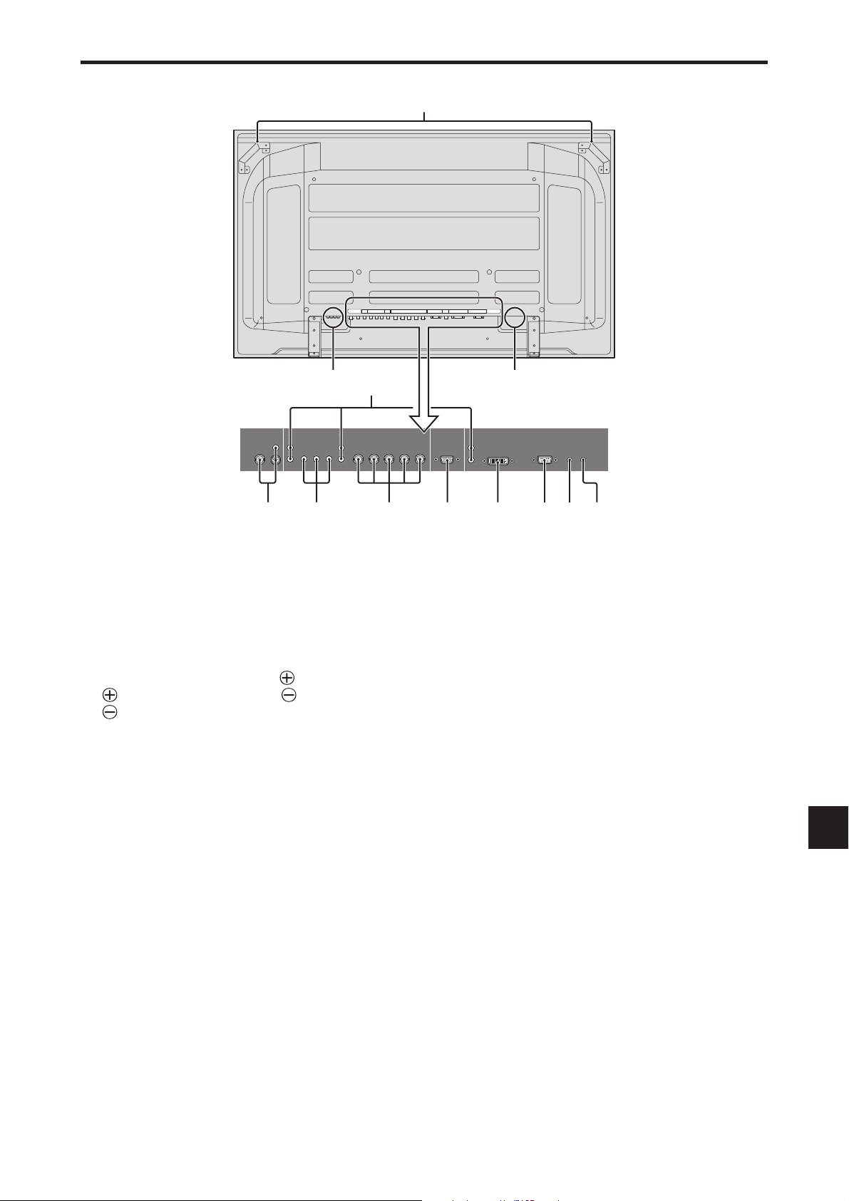
Vue arrière / Raccordements
60XM5
BA
AUDIO
DVD
1
/ HD
1
AUDIO
1
VIDEO
2
(IN/OUT)
R
3
L
(
MONO
1
Y Cb/Pb Cr/Pr
)
R
(
MONO
L
VIDEO
AUDIO
1
D
2
R/Cr/Pr G/Y B/Cb/Pb
)
DVD
YL/R L/RCb/Pb Cr/Pr
L
AUDIO
1
/ HD
1
RGB
2
/ DVD2 / HD
2
RGB
2
R/Cr/Pr G/Y B/ Cb/Pb
RGB
2
/ DVD2 / HD
1
AUDIO
3
RGB 3EXTERNAL CONTROL
(IN/OUT)
VD L/RHD
2
RGB
VDHD
(IN/OUT)
REMOTE
IN OUT
DVI
1
AUDIO
3
RGB
3
R
(
)
Digital RGB
DVI
(
)
L
MONO
EXTERNAL CONTROL
REMOTE
IN OUT
CE F GHIJK
A AC IN (ENTREE DU CORDON
D’ALIMENTATION ELECTRIQUE CA)
Branchement du câble d’alimentation fourni avec l’appareil.
B EXT SPEAKER L et R (HP EXT. G et D)
Connexions des haut-parleurs (option). Bien respecter
la polarité. Raccorder le câble
EXT SPEAKER et le câble (négatif) à la borne
EXT SPEAKER pour chaque canal GAUCHE et
DROIT.
Voir le mode d’emploi des haut-parleurs.
C VIDEO1, 2, 3 (BNC, RCA, S-Video)
Raccorder ici les magnétoscopes (VCR), les lecteurs
de DVD ou les vidéoscopes.
VIDEO1 peut être utilisé en entrée ou en sortie.
D AUDIO1, AUDIO2, AUDIO3
Bornes audio.
Cette entrée est sélectionnable. Régler le type d’image
vidéo à afficher sur l’écran de menu.
E DVD1 / HD1
Connexions pour DVD, lecteur laser vidéo haute
définition, etc.
F RGB2/ DVD2/ HD2
RGB2: Entrée du signal RGB analogique et du
signal de synchronisation.
DVD2/HD2: Vous pouvez connecter ici des DVD,
des sources Haute Définition, des
disques lasers, etc.
Cette entrée peut être réglée pour une
utilisation avec une source RGB ou
composant.
(positif) à la borne
G RGB1 (mini D-sub à 15 broches)
Raccorder ici les signaux RGB analogiques provenant
d’un ordinateur ou autre. Ce connecteur peut être utilisé
en entrée ou en sortie.
H RGB3 (DVI à 24 broches)
Connecter un signal numérique (TMDS) à partir d’une
source équipée d’une sortie DVI.
Cette entrée peut être réglée pour une utilisation avec
une source RGB3.
I EXTERNAL CONTROL (COMMANDE
EXTÉRIEURE)
Cette borne est à utiliser pour la commande et le
contrôle extérieurs (par RS-232C) du moniteur.
J REMOTE IN
Pour permettre la commande à distance câblée,
raccorder le câble de télécommande au jack
télécommande de la télécommande.
K REMOTE OUT
Pour permettre une commande à distance câblée,
raccorder le câble de télécommande au jack REMOTE
IN de l’autre moniteur d’affichage.
L Poignées
Utiliser lors de l’installation ou du transport du
moniteur plasma.
Fr-11

Télécommande
q POWER ON/STANDBY (Alimentation électrique)
Allume/met l’appareil en attente.
(Cela ne fonctionne pas quand l’indicateur POWER/
STANDBY de l’appareil principal est éteint.)
w RGB/PC
Appuyer sur cette touche pour choisir RGB/PC comme source.
RGB/PC peut aussi être sélectionné en utilisant le bouton INPUT SELECT sur le moniteur.
e DVD / HD
Appuyer sur cette touche pour choisir DVD/HD
comme source.
DVD/HD peut aussi être sélectionné en utilisant le bouton INPUT SELECT sur le moniteur.
r VIDEO
Appuyer sur cette touche pour choisir VIDÉO comme
source.
VIDÉO peut aussi être sélectionné en utilisant le bouton INPUT SELECT sur le moniteur.
t MENU/ENTER
Appuyer sur ce bouton pour accèder aux commandes OSM.
Appuyer sur ce bouton pendant l’affichage du menu
principal pour aller dans les sous-menus.
y CURSOR (▲ / ▼ /
Utiliser les touches pour sélectionner des articles ou
des réglages ainsi que pour effectuer les réglages ou
commuter l’affichage.
→ VIDEO1 → VIDEO2 → VIDEO3
/ )
u EXIT
Appuyer sur ce bouton pour sortir des commandes
OSM dans le menu principal. Appuyer sur ce bouton
pendant l’affichage d’un sous-menu pour retourner au
menu précédent.
i POINTER
Appuyer sur ce bouton pour afficher le pointeur.
o ZOOM (+ /–)
Elargit ou réduit la taille de l’image.
!0 VOLUME (+ /–)
Réglage du volume sonore.
!1 MUTE
Met le son en sourdine.
!2 WIDE
Appuyer sur ce bouton pour sélectionner et changer le
format d’image.
La touche “WIDE” (large) ne fonctionne pas pour tous
les signaux.
!3 DISPLAY
Affiche la source sélectionnée à l’écran.
!4 OFF TIMER
Active la temporisation de la coupure de l’alimentation.
!5 SIDE BY SIDE
Appuyez sur cette touche pour afficher des images en
mode côte-à-côte.
!6 PICTURE IN PICTURE
Appuyez sur cette touche pour afficher des images en
mode image dans l’image.
!7 SINGLE
Annule le mode de division de l’écran.
!8 SELECT/FREEZE
Appuyer sur cette touche pour sélectionner l'image
active en mode d'écran multi.
Lorsque la fonction GEL IMAGE est en
fonctionnement, cette touche peut être utilisée pour
afficher les images fixes sur le sous-écran.
!9 AUTO ADJUST
Appuyer sur cette touche pour que les réglages de piqué,
ajustement d'image, position et contraste soient
automatiquement effectués. Appuyer également sur cette
touche pour faire passer automatiquement le format
d'écran en mode ZOOM avec la légende superposée ne
s'affichant complètement que lorsque l'image contient des
parties sombres au-dessus et au-dessous.
@0 ID SELECT (SÉLECT. ID)
Entrer le numéro d’identification (ID) dans la
télécommande. Cette télécommande n’est utilisable
qu’avec un écran d’affichage de même numéro d’ID.
Quand plusieurs écrans sont utilisés simultanément,
leur commande peut s’effectuer individuellement.
@1 CLEAR (EFFACER)/SEAMLESS SW
Pour effacer le numéro entré à l’aide de la touche ID
SELECT.
Lorsque la fonction SEAMLESS SW est en
fonctionnement, cette touche peut être utilisée pour
commuter rapidement la source d’entrée.
@2 Transmetteur de signaux de la télécommande
Transmet les signaux de commande à distance.
@3 Prise Jack de la télécommande
Insérer la fiche du câble de télécommande (Le mini-câble
stéréo 1/8) lors de l’utilisation de la télécommande reliée
Fr-12
par câble.
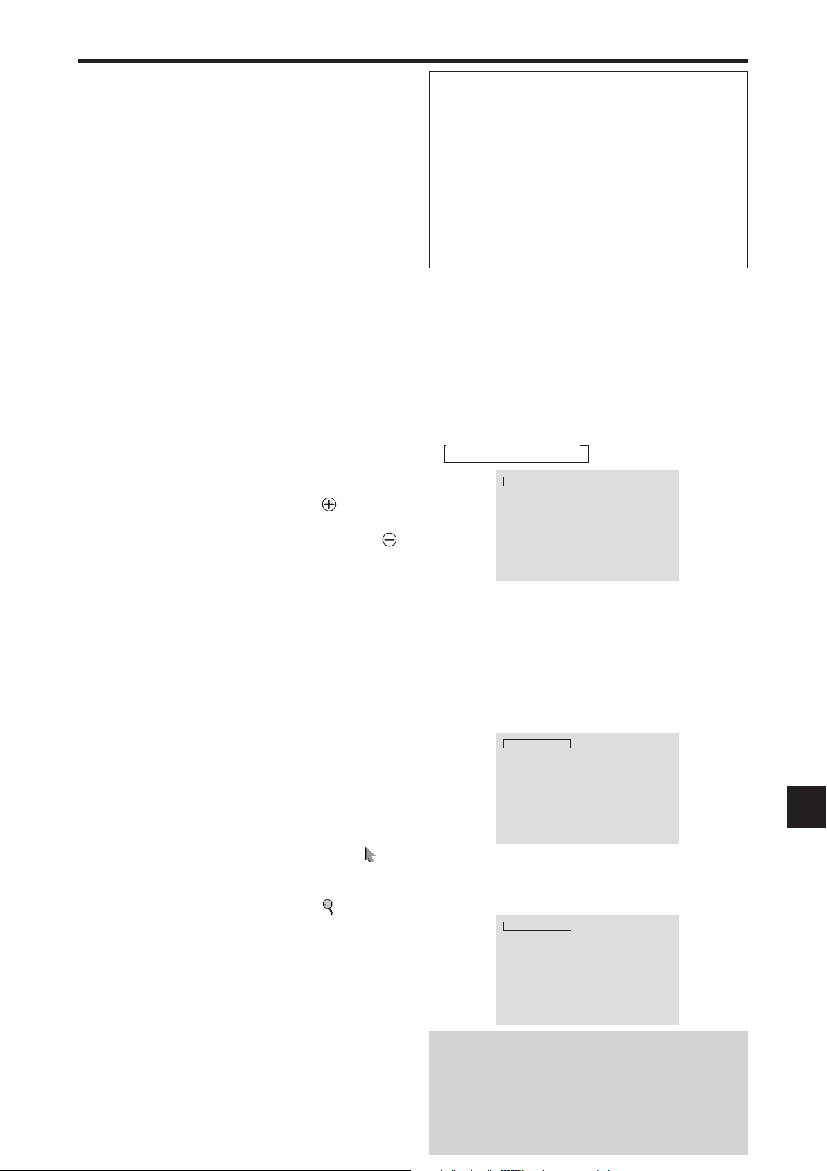
Fonctions de base
POWER (MARCHE/ARRÊT)
Pour mettre en marche et arrêter l’appareil :
1. Relier le câble d’alimentation à une prise active du secteur.
2. Appuyer sur la touche d’alimentation électrique (Power)
(de l’appareil).
Le voyant POWER/STANDBY (MARCHE/VEILLE) sur
le moniteur s’allume en rouge pour indiquer que ce dernier
est en veille.
3. Appuyer sur la touche POWER ON (de la télécommande)
pour mettre le moniteur en marche.
Le voyant POWER/STANDBY (MARCHE/VEILLE) sur
le moniteur s’allume en vert pour indiquer que ce dernier
est alimenté.
4. Pour mettre l’appareil hors tension, appuyer sur la touche
POWER STANDBY (de la télécommande) ou sur la
touche Power (alimentation électrique) de l’appareil.
Le voyant POWER/STANDBY (MARCHE/VEILLE) sur
le moniteur s’allume en rouge pour indiquer que ce dernier
est en veille (uniquement lorsqu'on éteint l'appareil avec
la télécommande).
VOLUME
Pour régler le volume sonore :
1. Pour amener le volume sonore au niveau souhaité, appuyer
et laisser le doigt sur la touche VOLUME
de télécommande ou de l’appareil).
2. Appuyer et maintenir le doigt sur la touche VOLUME
(de la télécommande ou du moniteur) pour réduire le
volume jusqu’au niveau souhaité.
(du boîtier
MUTE (SOURDINE)
Pour mettre le son en sourdine :
Appuyez sur la touche MUTE de la télécommande pour
couper le son ; appuyez de nouveau pour le rétablir.
DISPLAY (AFFICHAGE)
Pour vérifier les réglages :
1. Appuyer sur le bouton DISPLAY pour afficher le mode
d’affichage.
2. L’indication disparaît au bout d’environ trois secondes si
la touche n’est pas actionnée.
ZOOM NUMERIQUE
Le zoom numérique définit la position des images et élargit
les images.
1. (S’assurer que ZOOM NAVIG est à l’arrêt.)
)
.
Appuyer sur la touche POINTER pour l’afficher.(
Pour modifier la taille de l’image :
Appuyer sur le bouton ZOOM+ et élargir l’image.
Le pointeur prend la forme d’ une loupe. ( )
Une pression sur le bouton ZOOM- va réduire la taille de
l’image et la remettre à sa taille d’origine.
Pour modifier la position de l’image :
Sélectionner la position avec les boutons ▲▼
2. Appuyer sur la touche POINTER pour le faire disparaître.
AUTO ADJUST (REGLAGE AUTO)
Pour régler automatiquement le format et la
qualité de l’image:
Appuyer sur la touche AUTO ADJUST.
Informations
Paramètre AUTO ADJUST MARCHE
Lorsqu’une entrée RGB (image fixe) est sélectionnée:
Le réglages de piqué, ajustement d’image, position et
contraste seront automatiquement effectués.
Lorsque une entrée RGB (image animée), VIDEO
ou Y/Pb/Pr (composantes) est sélectionnée:
Le format d’image passe automatiquement en mode
ZOOM avec la légende superposée ne s’affichant
complètement que lorsque l’image contient des parties
sombres au-dessus et au-dessous.
OFF TIMER (ARRÊT TEMPORISÉ)
Réglage de la temporisation de l’alimentation :
La temporisation d’alimentation peut être réglée pour que le
moniteur s’éteigne seul au bout de 30, 60, 90 ou 120 minutes.
1. Appuyer sur la touche OFF TIMER pour régler la temporisation à 30 minutes.
2. Appuyer sur la touche OFF TIMER jusqu’à l’obtention
de la durée souhaitée.
La temporisation commence à partir du moment où le menu disparaît.
3.
→ 30 → 60 → 90 → 120 → 0
ARRET HORL 30
Vérification du temps restant avant l’arrêt
automatique:
1. Une fois la temporisation réglée, appuyer une nouvelle
fois sur la touche OFF TIMER.
2. Le temps restant avant l’arrêt automatique est affiché puis
disparaît après quelques secondes.
3. Pendant les cinq dernières minutes de temporisation, le
temps restant s’affiche jusqu’à l’arrêt automatique.
ARRET HORL 28
Annulation de la temporisation de l’alimentation:
1. Appuyer sur la touche OFF TIMER deux fois de suite.
2. La temporisation est annulée.
ARRET HORL 0
Remarque:
Après que l’alimenation est coupée par le mode de temporisation…
Un courant de faible intensité est toujours envoyé au
moniteur. Si l’on doit quitter les lieux ou ne pas utiliser le
système pendant une durée prolongée, il est préférable de
Fr-13
couper complètement l’alimentation du moniteur.

Fonctionnement avec écran large (WIDE)
Visualisation sur grand écran (manuel)
Cette fonction permet de sélectionner un des sept formats
d’écran.
Visualisation de vidéos ou de disques laser
vidéo
1. Appuyer sur la touche WIDE de la télécommande.
2. Dans les 3 secondes qui suivent...
Appuyer de nouveau sur cette touche WIDE.
Les formats d’écran défilent dans la séquence suivante:
→ NORMAL→ COMPLET→ STADIUM→ ZOOM → 2.35:1 → 14:9 → UNDERSCAN
A l’entrée d’un signal 720P ou 1080I:
COMPLET ↔ 2.35:1
Lors de l’affichage d’images Multi Ecran:
NORMAL ↔ COMPLET
Format d’écran NORMAL (4/3)
L’image est agrandie sur les axes vertical et horizontal
tout en conservant les proportions originales.
*Utiliser ce mode pour les films de format cinéma (large),
etc.
Format d’écran 2.35:1
佡
Image originale
Perte d’informations de
chaque côté
L’image filmée comprimée est agrandie au format de
l’écran dans un rapport de 2,35:1. Aucune bande noire
n’est visible en haut ou en bas de l’image mais certaines
informations sont perdues dans les marges gauche et droite.
• Cette fonction est active quand le signal d’entrée est de
type vidéo, composante (480I, 480P, 576I, 576P, 720P,
1080I) ou RGB (signal 525P ou 625P fourni par un
changeur de trame).
* Si une bande noire apparaît en haut ou en bas de l’image
en plein page écran, choisir le format d’écran 2,35:1 pour
éviter les marques de phosphore.
L’écran affiche l’image normale.
* L’image a les mêmes proportions que les images vidéo
avec un rapport 4/3.
Format d’écran COMPLET
L’image est étirée sur le plan horizontal.
* Les images compressées sur le plan horizontal sont étirées
sur le plan horizontal et affichées sur la largeur totale de
l’écran. (Les images normales sont étirées sur le plan
horizontal.)
Format d’écran STADIUM
Format d’écran 14:9
L’image est affichée avec un rapport 14:9.
* Cette fonction est disponible pour les signaux d’entrée de
type vidéo, composante (480I, 480P, 576I, 576P) ou RGB
(signal 525P ou 625P provenant d’un convertisseur de
balayage).
Format d’écran UNDERSCAN
Régler “UNDERSCAN” sur “MARCHE” dans
“REGLAGE IMAGE”.
Les télévisions ordinaires rognent les images (surbalayage). Afin de restaurer l’image dans son intégralité,
sélectionner UNDERSCAN.
L’image est agrandie sur les axes vertical et horizontal
avec des rapports différents.
* Utiliser ce format d’écran pour regarder les émissions de
vidéo normales (4/3) sur la totalité du grand écran.
Format d’écran ZOOM
Sous-balayage
* Du bruit d’image ou une bordure noire peut apparaître à
proximité du bord de l’écran en fonction du composant
connecté.
* L’affichage continu dans ce format d’écran pendant une
période prolongée peut entraîner une rétention d’image.
* Lorsque le signal Macrovision est entré, la luminosité peut
changer.
Remarque:
pendant une trop longue période de temps. Il y a risque de
vieillissement des luminophores.
Fr-14
ne pas laisser l’affichage en mode 4:3
Sur-balayage

Visualisation d’images
d’ordinateur sur le grand écran
Commuter vers le mode grand écran pour agrandir l’image
4/3 et remplir l’écran en entier.
1.Appuyer sur la touche WIDE de la télécommande.
2.Dans les 3 secondes qui suivent …
Appuyer de nouveau sur cette touche WIDE.
Les formats d’écran défilent dans la séquence suivante:
→ NORMAL → COMPLET → ZOOM
Lors de l’affichage d’images Multi Ecran:
NORMAL ↔ COMPLET
Format d’écran NORMAL (4/3 et SXGA 5/4)
L’image a les mêmes proportions qu’une image
d’ordinateur.
Format d’écran COMPLET
Format d’écran COMPLET
L’image est agrandie horizontalement et verticalement.
Format d’écran ZOOM
Lors d’une entrée de signaux Large (wide).
REELLE
L’image est à résolution réelle.
L’image est étirée sur le plan horizontal.
Format d’écran ZOOM
Lors d'une entrée de signaux Large (wide).
Format d’écran COMPLET
Quand “TAILLE IMAGE” est mis sur “ARRET”
* Ceci ne peut pas être réglé sur certains modèles. Dans ce
cas, la taille “REELLE” ne sera pas affichée.
Les formats d’écran défilent dans la séquence suivante:
→ REELLE → COMPLET → ZOOM
COMPLET
Informations
䡵 Résolutions disponibles
Voir la page Fr-43 pour plus de détails sur la sortie
d’affichage des différents standards VESA pouvant être
utilisés sur le moniteur.
䡵 Paramètre “TAILLE IMAGE”
Lorsque le paramètre “TAILLE IMAGE” est sur
ARRET, le format des images de l’entrée RGB est
REELLE au lieu de NORMAL.
䡵 Lors d'une entrée de signaux wide VGA* de
852 (848) points ✕ 480 lignes ayant une
fréquence verticale de 60 Hz et une
fréquence horizontale de 31,7 (31,0) kHz
Sélectionner une option appropriée pour le mode
SÉLECT. RVB en consultant le “Tableau des signaux
pris en charge” à la page Fr-43.
* “VGA”, “SVGA” et “SXGA” sont des marques
déposées de IBM, Inc. - Etats-Unis.
Format d’écran REELLE (VGA, SVGA 4:3)
L’image est à résolution réelle.
Remarque:
ne pas laisser l’affichage en mode 4:3
pendant une trop longue période de temps. Il y a risque de
vieillissement dlr luminophor es.
Fr-15
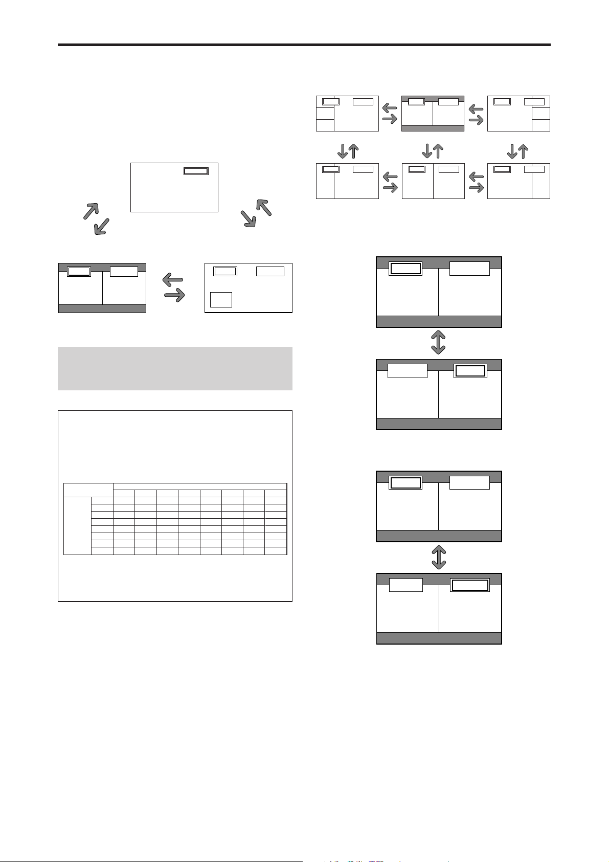
VIDEO1 RGB1
AB
VIDEO1RGB1
BA
VIDEO1 RGB1
AB
VIDEO1 RGB1
AB
Opérations de DECOUPE D’IMAGE
Affichage de deux images en même
temps sur l'écran
* Il se peut qu’une image de l’entrée RGB ne soit pas affiché
sur ces modes, en fonction des caractéristiques du signal
d’entrée.
1. Appuyer sur la touche pour sélection un mode d’écran
par les modes d’écran simple, côte à côte et image dans
image.
VIDEO1
bouton
SINGLE
bouton
SIDE BY SIDE
VIDEO1 RGB1
AB
A
bouton
PICTURE IN PICTURE
bouton
SIDE BY SIDE
bouton
PICTURE IN
PICTURE
VIDEO1 RGB1
Ecran
auxiliaire
Remarque:
L’image A et l’image B sur l’écran ci-dessous n’ont pas
toujours la même hauteur.
bouton
SINGLE
Ecran
principal
Opérations en mode côte-à-côte
Pour changer le format de l’image, appuyer sur le bouton
䊴 䊳
ou ▼ du curseur.
VIDEO1 RGB2
A
B
Côte-à-Côte2-R
bouton
䊲
VIDEO1 RGB2
A
B
Côte-à-Côte4-R
bouton
䊲
bouton
䊴
bouton
䊳
bouton
䊴
bouton
䊳
VIDEO1 RGB2
AB
Côte-à-Côte1 Côte-à-Côte2-L
bouton
䊲
VIDEO1 RGB2
AB
Côte-à-Côte3 Côte-à-Côte4-L
bouton
䊲
bouton
䊴
bouton
䊳
bouton
䊴
bouton
䊳
VIDEO1 RGB2
A
bouton
䊲
VIDEO1 RGB2
A
B
bouton
䊲
B
Pour afficher alternativement une image à droite et à
gauche, appuyer sur le bouton
䊱
du curseur.
bouton
䊱
Informations
Il se peut que les opérations de découpe d’image ne
fonctionnent pas, selon la combinaison de signaux
d’entrée. Dans le tableau suivant, “嘷” signifie Oui,
“⳯” signifie Non.
Images affichées sur l’écran principal/droit (Sélect1)
VIDEO2
VIDEO3
⳯
⳯
⳯
⳯
⳯
⳯
嘷
嘷
嘷
嘷
嘷
嘷
嘷
嘷
嘷
嘷
DVD/HD1
⳯
⳯
⳯
嘷
嘷
嘷
嘷
嘷
DVD/HD2
RGB1
RGB2
嘷
嘷
嘷
嘷
⳯
嘷
嘷
嘷
嘷
嘷
嘷
嘷
嘷
嘷
嘷
嘷
⳯
嘷
嘷
⳯
⳯
嘷
嘷
嘷
RGB3
嘷
嘷
嘷
嘷
嘷
嘷
嘷
嘷
⳯
嘷
嘷
嘷
⳯
嘷
嘷
⳯
Images
affichées sur
l’écran
secondaire/
gauche
(Sélect2)
VIDEO1
VIDEO2
VIDEO3
DVD/HD1
DVD/HD2
RGB1
RGB2
RGB3
VIDEO1
䡵 Il se peut que les opérations de découpe
d’image ne fonctionnent pas, selon le type
des signaux RGB.
Pour activer une image donnée, appuyer sur le bouton
SELECT/FREEZE.
bouton SELECT/
FREEZE
Fr-16

Opérations en mode image-dans-image
Pour changer de position sur l’écran secondaire, appuyer
䊴
sur le bouton
VIDEO1
A
Haut Gauche
䊳
bouton
VIDEO1 RGB2
A
Bas Gauche Bas Droite
ou 䊳 du curseur.
RGB2
B
bouton
B
bouton
䊳
VIDEO1
RGB2
A
B
bouton
䊴
Haut Droite
䊴
bouton
䊴
䊴
bouton
VIDEO1 RGB2
B
bouton
䊳
bouton
䊳
A
Pour changer le format de l’écran secondaire, appuyer sur
le bouton ▼ du curseur.
VIDEO1 RGB1
B
A
VIDEO1 RGB1
B
bouton 䊲
A
VIDEO1 RGB1
Sélection des signaux d'entrée à afficher
1. Appuyer sur la touche SELECT/FREEZE pour rendre
active l'image désirée.
2. Appuyer sur la touche RGB/PC, VIDEO ou DVD/HD.
À chaque pression sur la touche, le signal d'entrée
sélectionné change.
On peut également utiliser le bouton INPUT SELECT du
moniteur pour changer la sélection.
Zoomer les images
1. Appuyez sur la touche SELECT/FREEZE pour activer
l’image désirée.
2. Utilisez la touche POINTER et la touche ZOOM ⴐ/ⴑ
pour agrandir l’image.
Pour les détails, voir “ZOOM NUMERIQUE” à la page
Fr-13.
Réglage des commandes OSM
1. Appuyer sur la touche SELECT/FREEZE pour rendre
active l'image désirée.
2. Appuyer sur la touche MENU/ENTER pour afficher le
MENU PRINCIPAL.
3. Régler les paramètres selon ses préférences.
Pour plus d'informations, voir “Commandes OSM
(MENUS ÉCRAN)” à la page Fr-18.
B
bouton 䊲
A
VIDEO1 RGB1
B
bouton 䊲
bouton 䊲
Pour activer une image donnée, appuyer sur le bouton
SELECT/FREEZE.
VIDEO1 RGB1
B
A
bouton
SELECT/
FREEZE
A
VIDEO1 RGB1
B
A
Remarque:
En mode écran multi, certaines fonctions des commandes
OSM ne sont pas disponibles.
Fr-17
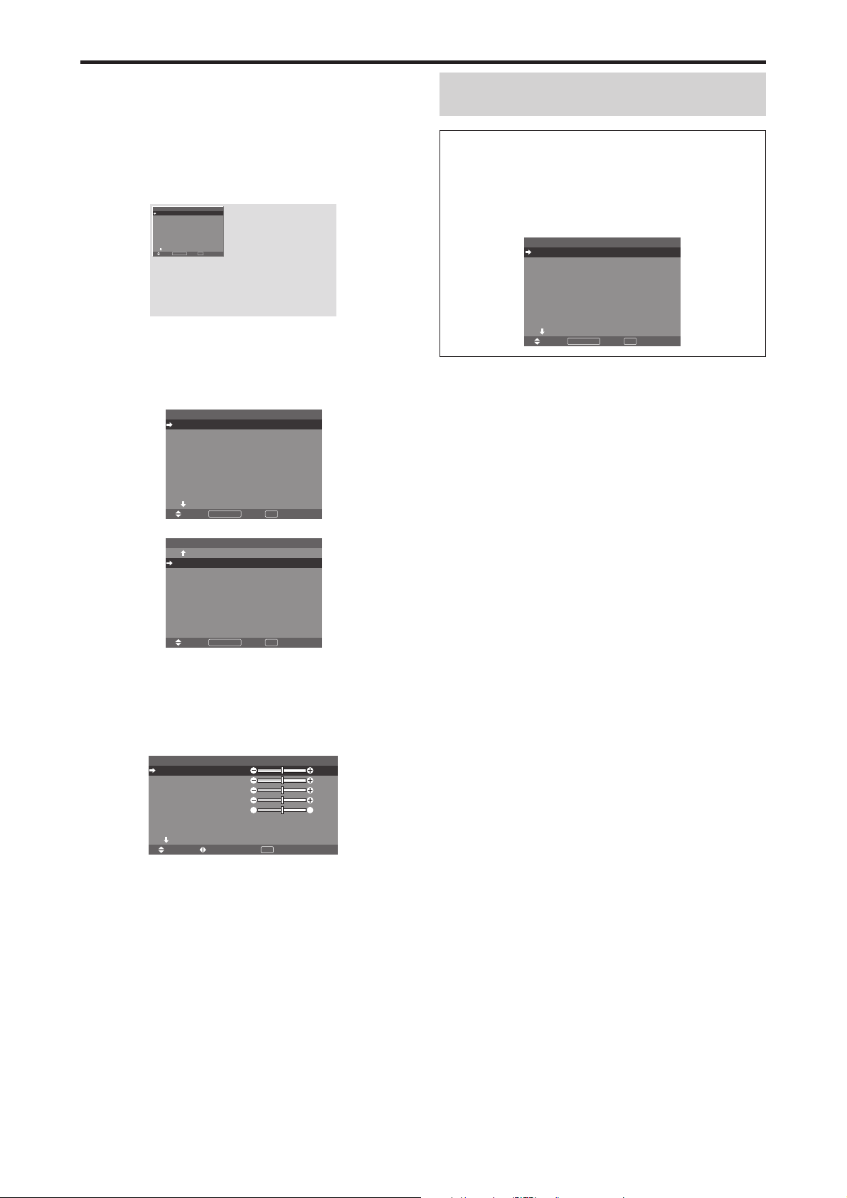
Commandes OSM (MENUS ÉCRAN)
Opérations de menu
La fenêtre OSM s’affiche sur l’écran exactement
comme indiqué sur le schéma.
* Selon le mode dans lequel se trouve l’écran, l’OSM
peut montrer un affichage différent.
Dans l’explication, l’affichage OSM est illustré en
gros plan.
MENU PRINCIPAL
IMAGE
AUDIO
REGLAGE IMAGE
OPTION1
OSM AVANCÉ
PAGE
SEL.
Ce chapitre décrit l’utilisation des menus et des rubriques
sélectionnées.
1. Appuyer sur la touche MENU/ENTER de la
télécommande pour accéder au MENU PRINCIPAL.
1 / 2
:
ARRET
+
MENU/ENTEROKEXIT
EXIT
MENU PRINCIPAL 1 / 2
IMAGE
AUDIO
REGLAGE IMAGE
OPTION1
OSM AVANCÉ
PAGE
MENU/ENTEROKEXIT
SEL.
+
: ARRET
EXIT
Remarque:
Le menu principal disparaît en appuyant
sur le bouton EXIT (sortie).
Informations
Mode menu avancé
Si “OSM AVANCÉ” est réglé sur “MARCHE” au menu
principal (1/2), toutes les rubriques du menu sont
affichées.
MENU PRINCIPAL 1 / 2
IMAGE
AUDIO
REGLAGE IMAGE
OPTION1
OPTION2
OPTION3
OPTION4
OSM AVANCÉ
PAGE
MENU/ENTEROKEXIT
SEL.
+
: MARCHE
EXIT
* L’écran réel peut être différent de ceux montrés dans
ce manuel.
MENU PRINCIPAL 2 / 2
MENU/ENTEROKEXIT
SEL.
-
EXIT
PAGE
LANGAGE
TV SYSTÈMES
SIGNAL INFORMATION
2. Appuyer sur les flèches ▲ ▼ de la télécommande pour
sélectionner le menu souhaité.
3. Appuyer sur la touche MENU/ENTER de la
télécommande pour activer le sous-menu ou la rubrique
souhaitée.
CONTRASTE
LUMINANCE
PIQUÉ
COULEUR
TEINTE
MODE IMAGE
NR
PAGE
SEL. ADJ. RETOUR
IMAGE 1 / 2
: NORMAL
+
: ARRET
EXIT
: 52
: 32
: 16
: 32
GR
: 32
4. Régler le niveau ou modifier le réglage de la rubrique
souhaité à l’aide des touches
la télécommande.
5. Le réglage ou le paramétrage est mémorisé.
La modification devient la référence jusqu’à nouveau
paramétrage.
6. Répéter les étapes 2 à 5 pour régler un paramètre
supplémentaire ou appuyer sur la touche EXIT (sortie) de
la télécommande pour retourner au menu principal.
* Lors du réglage à l’aide de la barre au bas de l’écran,
appuyez sur la touche
ou dans les 5 secondes. Si vous
ne le faites pas, la configuration actuelle est sauvegardée
et l’écran précédent apparaît.
Fr-18

Arborescence de menus
:La partie hachurée indique la valeur par défaut.
←→
: Appuyer sur le bouton
:Les rubriques du menu sont accessibles dans une fenêtre réglée quand OSM AVANCÉ est réglé sur MARCHE.
MENU PRINCIPAL SOUS-MENU SOUS-MENU 2 SOUS-MENU 3 SOUS-MENU 4 RÉINITIALISATION ANGLE OSM “V” REFERENCE
IMAGE CONTRASTE ←→ 0←52→72 OUI OUI Fr-21
LUMINANCE ←→ 0←32→64 OUI OUI Fr-21
PIQUÉ ←→ 0←16→32 OUI OUI Fr-21
COULEUR ←→ 0←32→64 OUI OUI Fr-21
TEINTE R←→G 0←32→64 OUI OUI Fr-21
MODE IMAGE CLAIR/NORMAL/CINEMA1/CINEMA2/DEFAUT OUI OUI Fr-21
NR ARRET/NR-1/NR-2/NR-3 OUI OUI Fr-21
TEMP. COUL BASSE -/BASSE +/MEDIUM/HAUTE OUI OUI Fr-21
BALANCE DES BLANCS
GAMMA 1←→2←…→4 OUI NON Fr-22
TON BAS *
REGL COULEUR ROUGE J←→M0←32→64 OUI NON Fr-22
4
LUM. ROUGE ←→ 0←40→70 OUI NON Fr-22
LUM. VERTE ←→ 0←40→70 OUI NON Fr-22
LUM. BLEUE ←→ 0←40→70 OUI NON Fr-22
CONT. ROUGE ←→ 0←40→70 OUI NON Fr-22
CONT. VERTE ←→ 0←40→70 OUI NON Fr-22
CONT. BLEUE ←→ 0←40→70 OUI NON Fr-22
RESET ARRET←→MARCHE OUI NON Fr-22
MODE1←→MODE2 OUI NON Fr-22
VERT C←→J0←32→64 OUI NON Fr-22
BLEU M←→C0←32→64 OUI NON Fr-22
JAUNE V←→R0←32→64 OUI NON Fr-22
MAGENTA R←→B0←32→64 OUI NON Fr-22
CYAN B←→V0←32→64 OUI NON Fr-22
RESET ARRET←→MARCHE OUI NON Fr-22
ou pour régler.
MENU PRINCIPAL SOUS-MENU SOUS-MENU 2 SOUS-MENU 3 SOUS-MENU 4 RÉINITIALISATION ANGLE OSM “V” REFERENCE
AUDIO BASSE ←→ 0←13→26 OUI OUI Fr-23
AIGUE ←→ 0←13→26 OUI OUI Fr-23
BALANCE L←→R -22←0→+22 OUI OUI Fr-23
AUDIO INPUT1 VIDEO 1-3 / DVD/HD 1-2 / RGB 1-3 OUI OUI Fr-23
AUDIO INPUT2 VIDEO 1-3 / DVD/HD 1-2 / RGB 1-3 OUI OUI Fr-23
AUDIO INPUT3 VIDEO 1-3 / DVD/HD 1-2 / RGB 1-3 OUI OUI Fr-23
MENU PRINCIPAL SOUS-MENU SOUS-MENU 2 SOUS-MENU 3 SOUS-MENU 4 RÉINITIALISATION ANGLE OSM “V” REFERENCE
REGLAGE IMAGE MODE NORMAL/COMPLET/STADIUM/ZOOM/2.35:1/14:9/UNDERSCAN/REELLE*
V-POSITION ←→ -64←0→+64 OUI OUI Fr-23
H-POSITION ←→ -128←0→+127 OUI OUI Fr-23
V-HAUTEUR ←→ 0←→64 OUI OUI Fr-23
H-LARGEUR ←→ 0←→64 OUI OUI Fr-23
RÉGLAGE AUTO ARRET←→MARCHE*
1
RÉG FIN*
RÉG. IMAGE*
UNDERSCAN ARRET←→MARCHE OUI NON Fr-23
MENU PRINCIPAL SOUS-MENU SOUS-MENU 2 SOUS-MENU 3 SOUS-MENU 4 RÉINITIALISATION ANGLE OSM “V” REFERENCE
OPTION1 OSM AFFICHER OSM ARRET←→MARCHE OUI OUI Fr-24
SELECT BNC RGB←→COMP. OUI OUI Fr-24
SELECT D-SUB RGB — OUI Fr-24
SÉLECT. RVB AUTO OUI OUI Fr-24
HD SELECT 1080B/1035I/1080A NON OUI Fr-25
SELECT SKIP ARRET←→MARCHE OUI OUI Fr-25
ALL RESET ARRET←→MARCHE — OUI Fr-25
←→*20←→64 OUI OUI Fr-23
1
←→*20←→64 OUI OUI Fr-23
AJUST OSM 1←…→6 OUI OUI Fr-24
ANGLE OSM HOR.←→V OUI OUI Fr-24
POSITION OSM ARRET←→MARCHE OUI OUI Fr-24
CONTRAST. OSM BASSE-←→NORMAL OUI OUI Fr-24
2
3
— OUI Fr-23
NON OUI Fr-23
Fr-19

MENU PRINCIPAL SOUS-MENU SOUS-MENU 2 SOUS-MENU 3 SOUS-MENU 4 RÉINITIALISATION ANGLE OSM “V” REFERENCE
OPTION2 ECO ÉNERGIE ARRET←→MARCHE OUI NON Fr-26
MODE CINEMA ARRET←→MARCHE OUI NON Fr-26
LONGUE DURÉE PLE AUTO/VERROU1/VERROU2/VERROU3 OUI NON Fr-26
ROTATION PIX AUTO 1 OUI NON Fr-27
INVERSION ARRET OUI NON Fr-27
SCREEN WIPER ARRET OUI NON Fr-28
FOCUS LEGER ARRET/1/2/3/4 OUI NON Fr-28
NIVEAU GRIS 0←…→3←…→15 OUI NON Fr-28
S1/S2 AUTO←→ARRET OUI NON Fr-29
TAILLE IMAGE*
DVI SET UP PLUG/PLAY PC←→STB/DVD NON NON Fr-29
PROTOCOLE ARRET←→MARCHE OUI NON Fr-29
CLOSECAPTION ARRET←→CC1~4←→TEXTE1~4 OUI NON Fr-30
CAPTION CONT. BAS←→NORMAL OUI NON Fr-30
MENU PRINCIPAL SOUS-MENU SOUS-MENU 2 SOUS-MENU 3 SOUS-MENU 4 RÉINITIALISATION ANGLE OSM “V” REFERENCE
OPTION3 TIMER HORLOGE HEURE D ETE ARRET←→MARCHE NON NON Fr-30
POWER ON ENTREE LAST / MULTI / VIDEO 1-3 / DVD/HD 1-2 / RGB 1-3 OUI NON Fr-32
VERROUILLAGE ARRET←→MARCHE OUI NON Fr-32
IR REMOTE ARRET←→MARCHE OUI NON Fr-33
MODE BOUCLE ARRET←→MARCHE OUI NON Fr-33
ID CONNEXION ALL←→1←…→4 NON NON Fr-33
NUMERO ID ALL←→1←…→256 OUI NON Fr-33
MUR D’IMAGE DECOUPAGE ARRET/1/22/33/44/55/51/15 OUI NON Fr-34
MENU PRINCIPAL SOUS-MENU SOUS-MENU 2 SOUS-MENU 3 SOUS-MENU 4 RÉINITIALISATION ANGLE OSM “V” REFERENCE
OPTION4 2EME SOURCE DETECTION ARRET←→AUTO OUI NON Fr-36
ZOOM NAVIG ARRET←→CT A CT←→BAS GCH←→BAS DRT←→HT DRTE←→HT GCH OUI NON Fr-36
GEL IMAGE ARRET←→CT A CT1←→CT A CT2←→BAS GCH←→BAS DRT←→HT DRTE←→HT GCH OUI NON Fr-37
SEAMLESS SW ARRET OUI NON Fr-37
AFFICH. TEXT ARRET / BAS-1 / BAS-2 / BAS-3 / 1/2 INF. / 1/2 SUP. / HT-3 / HT-2 / HT-1 / GAUCHE / DROITE OUI NON Fr-38
MENU PRINCIPAL SOUS-MENU SOUS-MENU 2 SOUS-MENU 3 SOUS-MENU 4 RÉINITIALISATION ANGLE OSM “V” REFERENCE
OSM AVANCÉ ARRET←→MARCHE OUI NON Fr-38
LANGAGE ENGLISH/DEUTSCH/FRANÇAIS/ESPAÑOL/ITALIANO/SVENSKA/У/PORTUGUÊS NON NON Fr-38
TV SYSTÈMES AUTO/3.58 NTSC/4.43 NTSC/PAL/PAL 60/PAL-N/PAL-M/SECAM NON OUI Fr-39
SIGNAL INFORMATION
— — OUI Fr-39
3
ARRET←→MARCHE OUI NON Fr-29
BLACK LEVEL LOW←→HIGH NON NON Fr-29
TIMER ARRET OUI NON Fr-31
VOLUME LAST←→0←…→42 OUI NON Fr-32
POSITION
AFFICHAGE SPRIT←→BLANC OUI NON Fr-34
AUTO ID ARRET←→MARCHE OUI NON Fr-34
TRAME MODE
ON. DIFFÉRÉ ARRET/MARCHE/MODE1/MODE2 OUI NON Fr-35
PLE LINK ARRET←→MARCHE OUI NON Fr-35
TRANSPARENCE 20%←…→100% OUI NON Fr-36
AFFICHAGE FONDU←→NORMAL OUI NON Fr-36
MARCHE SÉLECT1/SÉLECT2 OUI NON Fr-37
AUTO 2 OUI NON Fr-27
MANUEL PIXEL H/LIGNE V/DURÉE OUI NON Fr-27
ARRET OUI NON Fr-27
MARCHE TEMPS FONCT./TEMPS ATTEN. OUI NON Fr-27
BLANC OUI NON Fr-27
MARCHE TEMPS FONCT./TEMPS ATTEN./VITESSE OUI NON Fr-28
JOUR/HEURE/MINUTES NON NON Fr-30
PROG. JOUR/ON/OFF(HEURE/MINUTES)/ENTRÉE/FONCT. OUI NON Fr-31
REPETER SIMPLE/MULTI/M.VIDEO OUI NON Fr-32
No.1←…→No.4/No.7←…→No.15/No.16←…→No.31/No.32←…→No.56
V-POSITION/H-POSITION/V-HAUTEUR/H-LARGEUR/RÉGLAGE AUTO/
RÉG FIN*
ENTREE/DETECTION/TRSPARENCE/AFFICHAGE OUI NON Fr-38
NORMAL/COMPLET/STADIUM/ZOOM/2.35:1/14:9/UNDERSCAN/REELLE
1
/RÉG. IMAGE*1/UNDERSCAN
— NON Fr-34
*3— NON Fr-35
*1 Uniquement lorsque RÉGLAGE AUTO est désactivé.
*2 RGB uniquement.
*3 “TAILLE IMAGE” et “REELLE” ne s’appliquent qu’aux écrans de type 50 et 60 pouces.
*4 “TON BAS” ne s’applique qu’aux écrans de type 50 pouces.
Informations
Restauration des réglages par défaut (réglage d’usine)
Sélectionner “ALL RESET” sous le menu de OPTION1. Noter que cette action restaure tous les réglages d’usine par défaut.
Fr-20

Menu de réglage de l’image
Réglage de l’image
Le contraste, la luminance, le piqué, la couleur et la teinte
peuvent être réglés à la demande.
Exemple: Régler le contraste
Sur “CONTRASTE” dans le menu “IMAGE”, réglez le
contraste.
CONTRASTE
LUMINANCE
PIQUÉ
COULEUR
TEINTE
MODE IMAGE
NR
PAGE
SEL. ADJ. RETOUR
Remarque:
IMAGE 1 / 2
: NORMAL
: ARRET
+
EXIT
Si le message “PAS DE RÉGLAGE”
apparaît...
Vérifier qu’en entrant dans le sous-menu IMAGE que le
MODE IMAGE n’est pas réglé sur DEFAUT.
Informations
䡵 Écran de réglage de l’image
CONTRASTE: Règle le contraste de l’image.
LUMINANCE: Règle la LUMINANCE de l’image.
PIQUÉ: Règle le piqué de l’image. Règle le détail de
l’image de l’affichage VIDEO.
COULEUR: Règle la densité de la couleur.
TEINTE: Règle la teinte de l’image.
Réglage pour une couleur de peau naturelle, du fond, etc.
䡵 Réglage des images d’ordinateur
Pour les images d’ordinateur, seul le contraste et la LUMINANCE peuvent être réglés.
䡵 Restauration des réglages par défaut
(réglage d’usine)
Appuyer sur la touche “DEFAUT” des option de réglage
du “MODE IMAGE”.
Réglage du mode d’affichage en fonction de
l’éclairage ambiant
Quatre modes d’affichage sont disponibles pour obtenir
la meilleure image selon l’éclairage ambiant.
Exemple: Sélection du mode “CINEMA1”
Sur “MODE IMAGE” dans le menu “IMAGE”, sélectionnez
“CINEMA1”.
CONTRASTE
LUMINANCE
PIQUÉ
COULEUR
TEINTE
MODE IMAGE
NR
PAGE
SEL. ADJ. RETOUR
IMAGE 1 / 2
: NORMAL
: ARRET
+
EXIT
: 52
: 32
: 16
: 32
GR
: 32
CONTRASTE
: 52
: 32
: 16
: 32
GR
: 32
MODE IMAGE
:
CINEMA1
:
52
Informations
䡵 Mode d’affichage
CINEMA1, 2: Choisir ce mode pour visionner une cassette vidéo dans une pièce sombre.
Les images sont plus foncées et plus fines, comme sur un
écran de cinéma.
Pour une image plus sombre, sélectionner CINEMA2.
NORMAL: Ce mode s’utilise pour regarder la VIDEO
dans une pièce éclairée.
CLAIR: Ce mode fournit des images plus claires que le
mode NORMAL.
Les images sont dynamiques avec une nette différence
entre les zones claires et les zones sombres.
DEFAUT: S’utilise pour restaurer les réglages d’usine par
défaut.
Réduction du bruit de l’image (parasites)
Utiliser ce réglage si le bruit de l’image est du à une mauvaise réception ou à la qualité médiocre de la cassette vidéo.
Exemple: Réglage de “NR-3”
Sur “NR” dans le menu “IMAGE”, sélectionnez “NR-3”.
CONTRASTE
LUMINANCE
PIQUÉ
COULEUR
TEINTE
MODE IMAGE
NR
PAGE
SEL. ADJ. RETOUR
IMAGE 1 / 2
: NORMAL
: ARRET
+
EXIT
: 52
: 32
: 16
: 32
GR
: 32
NR
:
NR-3
Informations
䡵 NR
* “NR” signifie réduction du bruit.
* Cette fonction réduit le bruit de l’image (parasites).
䡵 Niveaux de réduction de bruit
Il existe trois types de réduction du bruit (parasites).
Chacun opère avec une intensité différente pour réduire
les parasites.
L’effet devient plus fort au fur et à mesure que le nombre
augmente (dans l’ordre NR-1 → NR-2 → NR-3).
ARRET: Désactive la réduction de bruit.
Réglage de la température de couleur
Utiliser cette fonction pour regler le ton de la couleur
produit par l’affichage plasma.
Exemple: Réglage sur “HAUTE”
Sur “TEMP. COUL” dans le menu “IMAGE”, sélectionnez
“HAUTE”.
IMAGE 2 / 2
PAGE
TEMP. COUL
GAMMA
TON BAS
REGL COULEUR
: HAUTE
: 2
: MODE1
SEL. ADJ. RETOUR
EXIT
Informations
䡵 Réglage de la température de la couleur
BASSE -: Plus de rouge
BASSE +: Un peu plus de rouge
MEDIUM: Normal (un peu plus de bleu)
HAUTE: Plus de bleu
Fr-21

Ajustement des couleurs à la qualité désirée
Pour le réglage de la balance du blanc dans chaque
température de couleur pour la qualité de couleur
souhaitée, procéder de la manière suivante.
Exemple : Réglage du “LUM. ROUGE” de la
température de couleur “HAUTE”
Régler “OSM AVANCÉ” sur “MARCHE” dans le MENU
PRINCIPAL.
Sur “TEMP. COUL” dans le menu “IMAGE”, sélectionnez
“HAUTE”, puis appuyez sur la touche MENU/ENTER.
L’écran “
BALANCE DES BLANCS
” apparaît.
Sur “LUM. ROUGE”, réglez l’équilibre de blanc.
BALANCE DES BLANCS
TEMP. COUL HAUTE
LUM. ROUGE
LUM. VERTE
LUM. BLEUE
CONT. ROUGE
CONT. VERTE
CONT. BLEUE
RESET
SEL. ADJ. RETOUR
: ARRET
EXIT
: 40
: 40
: 40
: 40
: 40
: 40
LUM. ROUGE
:
70
Réglages des Tons Bas
Vous pouvez choisir entre 2 modes de reproduction des
tons.
Cette fonction est particulièrement efficace pour les images
sombres.
* Cette fonction est disponible uniquement pour le type 50
pouces.
Exemple : Réglage sur “MODE2”
Régler “OSM AVANCÉ” sur “MARCHE” dans le MENU
PRINCIPAL.
Sur “TON BAS” dans le menu “IMAGE”, sélectionnez
“MODE2”.
IMAGE 2 / 2
PAGE
TEMP. COUL
GAMMA
TON BAS
REGL COULEUR
-
SEL. ADJ. RETOUR
: MEDIUM
: 2
: MODE2
EXIT
Informations
䡵 Ajustement de la balance des blancs
LUM.-RVB: Réglage de la balance des blancs pour le
niveau de blanc.
CONT.-RVB: Réglage de la balance des blancs pour le
niveau de noir.
RESET: Retour aux valeurs usine par défaut. Sélectionner
“MARCHE” à l’aide des touches 䊴 et 䊳 puis appuyer sur
la touche MENU/ENTER.
䡵 Restauration des réglages par défaut
(réglage d’usine)
Sélectionner “RESET” sous le menu de
BLANCS
.
BALANCE DES
Modification de la courbe gamma
Cette fonction permet de régler la luminosité dans la zone
des tons moyens sans modifier les ombres et les mises en
lumière.
Exemple : Réglage sur “3”
Régler “OSM AVANCÉ” sur “MARCHE” dans le MENU
PRINCIPAL.
Sur “GAMMA” dans le menu “IMAGE”, sélectionnez “3”.
IMAGE 2 / 2
PAGE
TEMP. COUL
GAMMA
TON BAS
REGL COULEUR
-
SEL. ADJ. RETOUR
: MEDIUM
: 3
: MODE1
EXIT
Informations
䡵 Réglage de GAMMA
Plus le chiffre sélectionné est grand (dans l’ordre 1, 2,
3, 4), plus l’image est sombre.
Réglage des couleurs
Pour régler la luminance et la densité de couleur du rouge,
du vert, du bleu, du jaune, du magenta et du cyan, procéder
de la manière suivante.
Cette méthode permet d’accentuer le vert des arbres, le
bleu du ciel etc.
Exemple : Réglage du ton de couleur du bleu
Régler “OSM AVANCÉ” sur “MARCHE” dans le MENU
PRINCIPAL.
Sur le menu “IMAGE”, sélectionnez “REGL COULEUR”,
puis appuyez sur la touche MENU/ENTER.
L’écran “REGL COULEUR” apparaît.
Sur “BLEU” dans “REGL COULEUR”, réglez l’ajustement
de couleur.
ROUGE
VERT
BLEU
JAUNE
MAGENTA
CYAN
RESET
SEL. ADJ. RETOUR
REGL COULEUR
: ARRET
EXIT
MJ
: 32
JC
: 32
CM
: 32
RV
: 32
BR
: 32
VB
: 32
Informations
䡵 Réglage de REGL COULEUR
ROUGE: Pour procéder au réglage du rouge.
VERT: Pour procéder au réglage du vert.
BLEU: Pour procéder au réglage du bleu.
JAUNE: Pour procéder au réglage du jaune.
MAGENTA: Pour procéder au réglage du magenta.
CYAN: Pour procéder au réglage du cyan.
RESET: Retour aux valeurs usine par défaut. Sélectionner
䊴
“MARCHE” à l’aide des touches
et 䊳 puis appuyer sur
la touche MENU/ENTER.
Fr-22

Menu des réglages audio
Réglage des aigus des graves et de la
balance gauche/droit
L’équilibre droite/gauche, les graves et les aigus peurent
être réglés selon vos choix.
Exemple: Réglage des graves
Sur “BASSE” dans le menu “AUDIO”, régler les graves.
BASSE
AIGUE
BALANCE
AUDIO INPUT1
AUDIO INPUT2
AUDIO INPUT3
SEL. ADJ. RETOUR
Remarque:
AUDIO
: VIDEO1
: DVD/HD1
: RGB1
EXIT
Si le message “PAS DE RÉGLAGE”
: 26
: 13
RL
: ±0
apparaît…
Régler correctement “AUDIO INPUT (ENTREE
AUDIO)” dans le menu AUDIO.
Informations
䡵 Menu des réglages son
BASSE: Commande du niveau des basse-fréquences.
AIGUE: Commande du niveau des sons hautes-
fréquences.
BALANCE: Règle l’équilibre des canaux gauche et droit.
Réglage des emplacements des connecteurs
audio
Réglage des connecteurs AUDIO 1, 2, et 3 sur l’entrée
désirée.
Exemple: Régler “AUDIO INPUT1” sur “VIDEO2”
Sur “AUDIO INPUT1” dans le menu “AUDIO”, sélectionnez
“VIDEO2”.
Les sources disponibles dépendent des réglages de l’entrée.
BASSE
AIGUE
BALANCE
AUDIO INPUT1
AUDIO INPUT2
AUDIO INPUT3
SEL. ADJ. RETOUR
AUDIO
: VIDEO2
: DVD/HD1
: RGB1
EXIT
: 13
: 13
RL
: ±0
Informations
䡵 AUDIO INPUT (ENTREE AUDIO)
Un signal audio simple ne peut pas être choisi comme
canal sonore pour plus d’une borne d’entrée.
Menu des réglages de Réglage Image
Réglage de la position, de la taille, de la
finesse de l’image, de ses ajustements et du
sous-balayage
La position et le scintillement de l’image peuvent être corrigés.
Exemple:
Sur “V-POSITION” dans le menu “REGLAGE IMAGE”,
réglez la position.
En appuyant sur les touches
la séquence suivante :
NORMAL ↔ COMPLET
* Ce mode peut aussi être activé en appuyant sur la touche
WIDE (large) de la télécommande.
* Les réglages sur le menu REGLAGE IMAGE ne sont pas
fixés en usine.
Réglage de la position verticale en mode normal
䊴
et 䊳 , les modes défilent dans
REGLAGE IMAGE
MODE
V-POSITION
H-POSITION
V-HAUTEUR
H-LARGEUR
RÉ GLAGE AUTO
RÉ G FIN
RÉ G. IMAGE
UNDERSCAN
SEL. ADJ. RETOUR
: NORMAL
: ARRET
: ARRET
EXIT
: ±0
: ±0
: 0
: 0
: 0
: 0
V-POSITION
Informations
䡵 Lorsque “RÉGLAGE AUTO” est
désactivée (“ARRET”)
MODE
V-POSITION
H-POSITION
V-HAUTEUR
H-LARGEUR
RÉ GLAGE AUTO
RÉ G FIN
RÉ G. IMAGE
UNDERSCAN
REGLAGE IMAGE
SEL. ADJ. RETOUR
: COMPLET
: ARRET
: ARRET
EXIT
Lorsque Image auto est désactivé, les articles RÉG FIN
et RÉG. IMAGE sont affichés afin que vous puissiez
les régler.
䡵 Réglage de l’image automatique
MARCHE: Les réglages de l’image fine, de l’ajustement
de l’image et la position sont réalisés automatiquement.
Non disponible pour ZOOM numérique.
ARRET: Les réglages de l’image fine, de l’ajustement de
l’image et la position sont réalisés manuellement.
* Si RÉG FIN n’est pas possible, mettre Image Auto sur
ARRET (OFF) et procéder manuellement.
䡵 Réglage de la position de l’image
V-POSITION: Réglage de la position verticale de l’image.
H-POSITION: Réglage de la position horizontale de
l’image.
V-HAUTEUR: Ajuste la taille verticale de l’image.
(Sauf pour STADIUM)
H-LARGEUR: Réglage de la taille horizontale de l’image.
(Sauf pour STADIUM)
RÉG FIN*: Règle le scintillement.
RÉG. IMAGE*: Elimine les bandes horizontales de
l’image.
* Les fonctions ajustement de l’image et image fine ne
sont disponibles que lorsque le mode ’Réglage auto’
est désactivé (ARRET).
*RÉGLAGE AUTO, RÉG FIN et RÉG. IMAGE ne sont
possibles que pour les signaux RGB.
Mais ces options n’existent pas pour les films animés
en VIDEO, DVD/HD ou RGB.
䡵 Réglage du sous-balayage
Régler “OSM AVANCÉ” sur “MARCHE” dans le
MENU PRINCIPAL.
MARCHE: UNDERSCAN peut être sélectionné dans
MODE.
ARRET: UNDERSCAN ne peut pas être sélectionné
dans MODE.
* Ne peut être sélectionné que lorsqu’un signal vidéo est
entré.
Fr-23
: ±0
: ±0
: 32
: 32
: 32
: 32
:
+
64

Menu des réglages de Option1
Réglage du menu écran
Ce réglage permet de positionner le menu, le format de
l’affichage (horizontal ou vertical) etc.
Exemple : Mise hors fonction de AFFICHER OSM
Sur le menu “OPTION1”, sélectionnez “OSM”, puis appuyez
sur la touche MENU/ENTER.
L’écran “OSM” apparaît.
Sur “AFFICHER OSM” dans le menu “OSM”, sélectionnez
“ARRET”.
AFFICHER OSM
AJUST OSM
ANGLE OSM
POSITION OSM
CONTRAST. OSM
SEL. ADJ. RETOUR
Informations
䡵 Réglages de AFFICHER OSM
MARCHE: Les informations sur la taille d’écran, le
volume sonore, etc. apparaît.
ARRET: Les informations sur la taille d’écran, le volume
sonore, etc. n’apparaît pas.
La touche DISPLAY de la télécommande ne marchera
pas non plus.
䡵 Réglages de AJUST OSM
Permet de choisir la position du menu quand celui-ci
apparaît sur l’écran.
Le menu peut prendre l’une des positions 1 à 6
suivantes.
䡵 Réglages de ANGLE OSM
Permet de choisir le format de l’affichage (paysage
“HOR.” ou portrait “V”).
Si l’appareil est installé à la verticale, régle l’ANGLE
OSM sur “V”.
“HOR.”“V”
OPTION1 1 / 4
OSM
: RGB
SELECT BNC
: RGB
SELECT D-SUB
: AUTO
SÉLECT. RVB
: 1080B
HD SELECT
ARRET
:
SELECT SKIP
:
ARRET
ALL RESET
+
PAGE
EXIT
MENU/ENTER
SEL.
RETOUR
OK
* La langue du menu pour “V” est uniquement l’anglais.
* Certains éléments de menu, dont le mode LONGUE
DURÉE, ne seront pas affichés avec “V” mais peuvent
être effectués avec le réglage “HOR.” (Voir les pages
19 et 20 pour les éléments de menu qui peuvent être
affichés avec “V”).
OSM
: ARRET
: 1
: HOR.
: ARRET
: BASSE-
EXIT
OPTION1
OSM
SELECT BNC
: RGB
SELECT D-SUB
: RGB
SÉLECT. RVB
: AUTO
HD SELECT
: 1080B
SELECT SKIP
: ARRET
ALL RESET
: ARRET
1024ⴒ768
SEL.
MENU/ENTER
OK
EXIT
RETOUR
䡵 Réglages de POSITION OSM
MARCHE: La position du menu est décalée de huit points
chaque fois que OSM est affiché.
ARRET: L’OSM s’affiche toujours à la même position.
䡵 Réglages de CONTRAST. OSM
NORMAL: La luminosité de OSM est réglée sur normale.
BASSE-: La luminosité de OSM est réglée sur faible.
Réglage des connecteurs BNC
Sélectionner l’entrée des 5 connecteurs BNC sur RGB,
systèmes de composant.
Exemple: Régler le mode de “SELECT BNC” sur
“COMP.”
Sur “SELECT BNC” dans le menu “OPTION1”, sélectionnez
“COMP.”.
OSM
SELECT BNC
SELECT D-SUB
SÉ LECT. RVB
: AUTO
HD SELECT
SELECT SKIP
ALL RESET
PAGE
SEL. ADJ. RETOUR
OPTION1 1 / 4
: COMP.
: RGB
: 1080B
: ARRET
+
: ARRET
EXIT
Informations
䡵 Réglages de SELECT BNC
RGB: Utilise la borne 5BNC pour une entrée RGB.
COMP.: Utilise la borne 3BNC pour une entrée avec
système de composants.
Vérification des signaux transmis à la borne
RGB1
Utiliser cette fonction pour confirmer les signaux transmis
à la borne RGB1.
RGB est sélectionné et aucun réglage n’est possible.
OSM
SELECT BNC
SELECT D-SUB
SÉ LECT. RVB
: AUTO
HD SELECT
SELECT SKIP
ALL RESET
PAGE
PAS DE RÉGLAGE
OPTION1 1 / 4
: RGB
: RGB
: 1080B
: ARRET
+
: ARRET
Réglage d’une image d’ordinateur vers
l’écran de sélection de RGB correct
Sur l’image ordinateur, sélectionner le mode Sélect RGB
pour une image animée tel que mode (vidéo), mode large
ou émission numérique.
Exemple: Réglage du mode “SÉLECT. RVB” sur
“852⳯480”
Sur “SÉLECT. RVB” dans le menu “OPTION1”, sélectionnez
“852⳯480”.
OSM
SELECT BNC
SELECT D-SUB
SÉ LECT. RVB
: 852⳯480
HD SELECT
SELECT SKIP
ALL RESET
PAGE
SEL. ADJ. RETOUR
OPTION1 1 / 4
: RGB
: RGB
: 1080B
: ARRET
+
: ARRET
EXIT
Fr-24

Informations
䡵 Modes de SÉLECT. RVB
AUTO: Sélectionner le mode appropriée aux
caractéristiques des signaux d’entrée indiqués dans le
“Tableau des signaux pris en charge par l’appareil” à la
page Fr-43.
Les autres: Les résolutions disponibles sont montrées.
Voir page Fr-43 pour les détails des réglages ci-dessus.
Réglage de l´image haute définition vers une
taille d´ecran qui convient
Utiliser cette fonction pour définir si le nombre de lignes
verticales de l’image haute définition d’entrée est 1035 ou 1080.
Exemple: Réglage du mode “HD SELECT” sur
“1035I”
Sur “HD SELECT” dans le menu “OPTION1”, sélectionnez
“1035I”.
OSM
SELECT BNC
SELECT D-SUB
SÉ LECT. RVB
: AUTO
HD SELECT
SELECT SKIP
ALL RESET
PAGE
SEL. ADJ. RETOUR
OPTION1 1 / 4
: RGB
: RGB
I
1035
:
: ARRET
+
: ARRET
EXIT
Restauration des valeurs par défaut
Pour ramener tous les réglages (IMAGE, AUDIO,
REGLAGE IMAGE, OPTION1~4 etc.) aux valeurs usine
par défaut, procéder de la manière suivante.
Veuillez consulter la page Fr-19 pour les éléments à
réinitialiser.
Sur “ALL RESET” dans le menu “OPTION1”, sélectionnez
“MARCHE”, puis appuyez sur la touche MENU/ENTER.
OSM
SELECT BNC
SELECT D-SUB
SÉ LECT. RVB
: AUTO
HD SELECT
SELECT SKIP
ALL RESET
PAGE
SEL. ADJ. RETOUR
OPTION1 1 / 4
: RGB
: RGB
1080B
:
: ARRET
: MARCHE
+
EXIT
ALL RESET
RÉ GLAGES EN COURS
Lorsque l’écran “RÉGLAGES EN COURS” disparaît, puis
toutes les valeurs des réglages sont rétablies par défaut.
Informations
䡵 HD SELECT modes
Ces 3 modes ne sont pas affichés automatiquement dans
l’image correcte.
1080B: Emissions diffusées au standard numérique
1035I: Format de signal japonais “Haute Vision”
1080A: Emissions en numériques spéciales (par exemple
: DTC100)
Réglage de SELECT SKIP
Quand cette rubrique est réglée sur MARCHE, les signaux
non présents sont ignorés et seules les images dont les
signaux sont transmis seront affichées.
Ce réglage n’est possible que pour la touche INPUT
SELECT (SELECT ENTRÉE) de l’appareil.
Exemple : Réglage sur “MARCHE”
Sur “SELECT SKIP” dans le menu “OPTION1”, sélectionnez
“MARCHE”.
OSM
SELECT BNC
SELECT D-SUB
SÉ LECT. RVB
: AUTO
HD SELECT
SELECT SKIP
ALL RESET
PAGE
SEL. ADJ. RETOUR
OPTION1 1 / 4
: RGB
: RGB
1080B
:
: MARCHE
+
: ARRET
EXIT
Informations
䡵 Reglages de SELECT SKIP
ARRET: Tous les signaux sont balayés et affichés, que
ceux-ci soient présents ou non.
MARCHE: Si le signal d’entré n’est pas présent, il est
ignoré.
* Le message “RÉGLAGES EN COURS” s’affiche
pendant la recherche d’entrée.
Fr-25

Menu des réglages de Option2
Régler “OSM AVANCÉ” sur “MARCHE” dans le MENU
PRINCIPAL.
Sélection de l’alimentation pour images
d’ordinateur
Cette fonction d’économie d’énergie (alimentation) réduit
automatiquement la consommation du moniteur dès que
ce dernier reste inactif pendant un certain temps.
Exemple: Activation de la fonction d’économie
d’énergie
Sur “ECO ÉNERGIE” dans le menu “OPTION2”,
sélectionnez “MARCHE”.
OPTION2 2 / 4
PAGE
ECO ÉNERGIE
MODE CINEMA
LONGUE DURÉE
NIVEAU GRIS
S1/S2
TAILLE IMAGE
DVI SET UP
PROTOCOLE
CLOSECAPTION
CAPTION CONT
PAGE
Informations
䡵 Fonction d’économie d’énergie
* La fonction d’économie d’énergie réduit automa-
tiquement la consommation électrique du moniteur
si le clavier et la souris restent inactifs pendant un
certain temps. Cette fonction est disponible si
l’affichage de l’ordinateur.
* Si l’alimentation de l’ordinateur n’est pas fournie ou
si l’ordinateur et le moniteur ne sont pas branchés
correctement, le système se désactive.
* Pour tout détail supplémentaire sur la fonction
d’alimentation propre à l’ordinateur, se référer au
manuel d’utilisation de l’ordinateur.
䡵 Option de la fonction d’alimentation
MARCHE: La fonction d’économie d’énergie est activée.
ARRET: La fonction d’économie d’énergie est déactivée.
䡵 Indicateur de la fonction d’économie d’énergie
POWER/STANDBY (MARCHE/VEILLE)
L’indicateur POWER/STANDBY (MARCHE/VEILLE)
sur la face avant du moniteur indique l’état de la fonction
d’économie d’énergie. Voir ci-dessous pour plus de
détails sur le témoin d’état.
Indicateur POWER/STANDBY (MARCHE/VEILLE)
Mode de
gestion de
l’alimentation
électrique
On (Marche)
Off (Arrêt)
Indicateur
POWER/STANDBY
(MARCHE/VEILLE)
Vert
Rouge
-
+
SEL. ADJ. RETOUR
Etat de
fonctionnement de
la gestion
d’alimentation
Inactivé
Activé
: MARCHE
: MARCHE
: 3
: ARRET
: MARCHE
: ARRET
: ARRET
: BAS
EXIT
Description
Les signaux de
synchronisation horizontaux
et verticaux de l’ordinateur
sont présents.
Les signaux de
synchronisation horizontale
et/ou verticale ne sont pas
envoyés par l’ordinateur.
Restauration de l’image
L’image est déjà présente.
Actionner une touche du
clavier ou déplacer la souris.
L’image réapparaît.
Réglage de l’image pour s’adapter au format
cinéma
L’image au format film est détectée et projetée dans un
mode d’image adapté.
[Uniquement NTSC, PAL, PAL60, 480I (60 Hz), 525I (60
Hz), 576I (50 Hz), 625I (50 Hz), 1035I (60 Hz) et 1080I
(60 Hz)]
Exemple: Réglage de “MODE CINEMA” sur “ARRET”
Sur “MODE CINEMA” dans le menu “OPTION2”,
sélectionnez “ARRET”.
OPTION2 2 / 4
PAGE
ECO ÉNERGIE
MODE CINEMA
LONGUE DURÉE
NIVEAU GRIS
S1/S2
TAILLE IMAGE
DVI SET UP
PROTOCOLE
CLOSECAPTION
CAPTION CONT
PAGE
-
+
SEL. ADJ. RETOUR
: ARRET
: ARRET
: 3
: ARRET
: MARCHE
: ARRET
: ARRET
: BAS
EXIT
Informations
䡵 MODE CINEMA
MARCHE: Détection automatique du format de l’image
et projection dans le mode Cinéma.
ARRET: Le mode Cinéma ne fonctionne pas.
Réduction de la rémanence de l’image sur
l’écran
La luminosité de l’écran, la position de l’image, le mode
positif/négatif et le screen wiper (volets) sont réglés pour
réduire la production d’images rémanentes.
Sur le menu “OPTION2”, sélectionnez “LONGUE DURÉE”,
puis appuyez sur la touche MENU/ENTER.
L’écran “LONGUE DURÉE” apparaît.
PLE
ROTATION PIX
INVERSION
SCREEN WIPER
FOCUS LEGER
SEL. ADJ. RETOUR
LONGUE DURÉE
: AUTO
: AUTO1
: ARRET
: ARRET
: ARRET
EXIT
PLE (Peak Luminance Enhancement)
Cette fonction permet d’activer le limiteur de luminosité.
Exemple: Réglage de “PLE” sur “VERROU1”
Sur “PLE” dans le menu “LONGUE DURÉE”, sélectionnez
“VERROU1”.
PLE
ROTATION PIX
INVERSION
SCREEN WIPER
FOCUS LEGER
SEL. ADJ. RETOUR
LONGUE DURÉE
: VERROU1
: AUTO1
: ARRET
: ARRET
: ARRET
EXIT
Informations
䡵 Réglage de PLE
AUTO: Le réglage de la luminosité de l’écran est effectué
automatiquement en fonction de la qualité de l’image.
VERROU1, 2, 3: Réglage sur la luminosité maximum.
Le niveau de la luminosité diminue dans l’ordre VERROU
1, 2, 3. VERROU 3 garantit la luminosité maximale.
Fr-26

ROTATION PIX
Cette fonction permet permet de régler le décalage de
l’image.
Exemple: Réglage de “ROTATION PIX” sur “AUTO2”
Sur “ROTATION PIX” dans le menu “LONGUE DURÉE”,
sélectionnez “AUTO2”.
PLE
ROTATION PIX
INVERSION
SCREEN WIPER
FOCUS LEGER
LONGUE DURÉE
: AUTO
: AUTO2
: ARRET
: ARRET
: ARRET
INVERSION
Cette fonction permet de régler sur le mode inversion ou
d’afficher un écran blanc.
Exemple: Réglage de “INVERSION” sur “BLANC”
Sur “INVERSION” dans le menu “LONGUE DURÉE”,
sélectionnez “BLANC”.
PLE
ROTATION PIX
INVERSION
SCREEN WIPER
FOCUS LEGER
LONGUE DURÉE
: AUTO
: AUTO1
: BLANC
: ARRET
: ARRET
SEL. ADJ. RETOUR
EXIT
Informations
䡵 Réglages de ROTATION PIX
ARRET: Le mode Rotation PIX n’est pas en fonction.
Ceci est le réglage par défaut lorsque RGB est entré.
AUTO1: L’image se déplace de manière intermittente
autour de l’écran en réduisant de taille.
Ceci est le réglage par défaut lorsqu’un signal Vidéo ou
DVD/HD/DTV est entrée. Réglez sur “ARRET” lorsque
ces signaux ne sont pas utilisés.
AUTO2: L’image se déplace de manière intermittente
autour de l’écran en augmentant de taille.
MANUEL: Permet le réglage manuel de la fonction
Rotation PIX (Pixel horizontal, Ligne verticale et durée)
directement par l’utilisateur.
Voir les explications suivantes.
* Lorsqu’un signal Vidéo ou DVD/HD/DTV est entré,
les fonctions AUTO1 et 2 n’affecteront que les images
en mouvement et ne rendront l’écran ni plus petit ni
plus grand.
Régler manuellement la fonction ROTATION PIX
Régler la valeur du décalage et le temps entre deux
mouvements.
Exemple : Réglage pour un déplacement de l’image
de 2 points dans la direction horizontale et de 4 lignes
dans la direction verticale toutes les 3 minutes.
Sur “ROTATION PIX” dans le menu “LONGUE DURÉE”,
sélectionnez “MANUEL”, puis appuyez sur la touche
MENU/ENTER.
L’écran “ROTATION PIX” apparaît.
Réglez les éléments.
PIXEL H
LIGNE V
DURÉE
SEL. ADJ. RETOUR
ROTATION PIX
: 2DOT
: 4LINE
: 3M
EXIT
Informations
䡵 Réglages de la fonction ROTATION PIX
PIXEL H: Déplacement de 1 pixel à 20 pixels dans la
direction horizontale.
LIGNE V: Déplacement de 1 ligne à 20 lignes dans la
direction verticale.
DURÉE: Intervalle de 1 minute à 5 minutes (1 pixel
horizontal ou 1 ligne vertical par intervalle).
SEL. ADJ. RETOUR
EXIT
Informations
䡵 Réglages de la fonction INVERSION
MARCHE: L’image s’affiche alternativement en positif
et négatif.
Régler le temps en appuyant sur la touche MENU/ENTER
après avoir choisi “MARCHE”.
ARRET: La fonction inverse est inopérante.
BLANC: L’écran devient entièrement blanc. Régler le
temps en appuyant sur la touche MENU/ENTER après
avoir choisi “MARCHE”.
Réglage de la durée d’INVERSE/FOND BLANC
Permet de définir une durée.
Exemple: Paramétrage pour que le mode
INVERSION commence dans une heure et 30
minutes et se poursuive pendant deux heures.
Sur “INVERSION” dans le menu “LONGUE DURÉE”,
sélectionnez “MARCHE”, puis appuyez sur la touche
MENU/ENTER.
L’écran “INVERSE/FOND BLANC” apparaît.
Réglez les heures.
INVERSE/FOND BLANC
TEMPS FONCT.
TEMPS ATTEN.
SEL. ADJ. RETOUR
: 01H30M
: 02H00M
EXIT
Informations
䡵 Réglage de la durée
TEMPS FONCT.: Réglage de la durée de “INVERSE/
FOND BLANC”.
Si TEMPS FONCT. est réglé sur “MARCHE”, le mode
reste en fonction.
TEMPS ATTEN.: Réglage du temps d’attente jusqu’au
lancement de “INVERSE/FOND BLANC”.
* La fonction “TEMPS ATTEN.” ne peut pas être
déterminée quand “TEMPS FONCT.” est sur
MARCHE.
* Le “TEMPS FONCT.” et le “TEMPS ATTEN.” sont
réglables jusqu’à 12 heures et 45 minutes par unités
de 3 minutes.
* A la fin de la fonction TEMPS FONCT., le moniteur
passe en mode STANDBY.
[Exemple]
TEMPS FONCT.: 1h30
TEMPS ATTEN.: 2h00
←−−−− 2 H −−−−→←−− 1H30 −−→←−−−−
Fr-27
Marche
INVERSE/FOND BLANC Marche
STANDBY

䡵 Pour sélectionner “MARCHE” pour le
“TEMPS FONCT.”
Régler les heures du TEMPS FONCT. sur 0h et les
minutes sur 0mn. “MARCHE” apparaît.
SCREEN WIPER
Si cette fonction est réglée sur MARCHE, une barre
verticale blanche se déplace de manière répétitive et à
vitesse constante de gauche à droite de l’écran.
Exemple: Réglage de “SCREEN WIPER” sur
“MARCHE”
Sur “SCREEN WIPER” dans le menu “LONGUE DURÉE”,
sélectionnez “MARCHE”.
PLE
ROTATION PIX
INVERSION
SCREEN WIPER
FOCUS LEGER
LONGUE DURÉE
: AUTO
: AUTO1
: ARRET
: MARCHE
: ARRET
de 3 minutes.
䡵 Pour sélectionner “MARCHE” pour le
“TEMPS FONCT.”
Régler les heures du TEMPS FONCT. sur 0h et les
minutes sur 0mn. “MARCHE” apparaît.
FOCUS LEGER
Réduit les bords et adoucit l’image.
Exemple: Réglage de “FOCUS LEGER” sur “2”
Sur “FOCUS LEGER” dans le menu “LONGUE DURÉE”,
sélectionnez “2”.
PLE
ROTATION PIX
INVERSION
SCREEN WIPER
FOCUS LEGER
SEL. ADJ. RETOUR
LONGUE DURÉE
: AUTO
: AUTO1
: ARRET
: ARRET
: 2
EXIT
SEL. ADJ. RETOUR
EXIT
Informations
䡵 SCREEN WIPER
MARCHE: Si cette fonction est réglée sur MARCHE,
une barre verticale blanche se déplace de manière répétitive
et à vitesse constante de gauche à droite de l’écran.
ARRET: Le mode commutation par volet de l’écran est
hors fonction.
Réglage de la durée de SCREEN WIPER
Cette fonction permet de régler la durée et la vitesse du
SCREEN WIPER.
Exemple : Paramétrage pour que le mode VOLET
commence dans 30 minutes et se poursuive pendant
une heure et trente minutes.
Sur “SCREEN WIPER” dans le menu “LONGUE DURÉE”,
sélectionnez “MARCHE”, puis appuyez sur la touche
MENU/ENTER.
L’écran “SCREEN WIPER” apparaît.
Réglez les heures et la vitesse.
TEMPS FONCT.
TEMPS ATTEN.
VITESSE
SCREEN WIPER
SEL. ADJ. RETOUR
: 01H30M
: 00H30M
: 3
EXIT
Informations
䡵 Paramétrage du temps
TEMPS FONCT.: Permet de régler la durée du mode
“SCREEN WIPER”.
Si le “TEMPS FONCT.” est réglé sur “MARCHE”, cette
durée est infinie.
TEMPS ATTEN.: Permet de régler le temps d’attente
avant l’entrée dans le mode “SCREEN WIPER”.
VITESSE: Permet de régler la vitesse de la commutation
par “SCREEN WIPER” de l’écran. Plus le nombre est
grand plus la vitesse est rapide.
* La fonction “TEMPS ATTEN.” ne peut pas être
déterminée quand “TEMPS FONCT.” est sur
MARCHE.
* Le “TEMPS FONCT.” et le “TEMPS ATTEN.” sont
réglables jusqu’à 12 heures et 45 minutes par unités
Informations
䡵 Réglages du FOCUS LEGER
ARRET: La fonction FOCUS LEGER est désactivée.
1, 2, 3, 4: Active la fonction FOCUS LEGER. Plus le
nombre est grand plus l’image est adoucit.
“PIQUÉ” ne peut pas être réglé dans le menu “IMAGE”.
Réglage du niveau des gris pour les côtés
de l’écran
Utiliser cette fonction pour régler le niveau de gris des
par-ties latérales de l’écran sur lesquelles rien n’est affiché
lorsque l’écran est réglé au format 4/3.
Exemple: Réglage de “NIVEAU GRIS” sur “5”
Sur “NIVEAU GRIS” dans le menu “OPTION2”,
sélectionnez “5”.
OPTION2 2 / 4
PAGE
ECO ÉNERGIE
MODE CINEMA
LONGUE DURÉE
NIVEAU GRIS
S1/S2
TAILLE IMAGE
DVI SET UP
PROTOCOLE
CLOSECAPTION
CAPTION CONT
PAGE
-
+
SEL. ADJ. RETOUR
: ARRET
: MARCHE
: 5
: ARRET
: MARCHE
: ARRET
: ARRET
: BAS
EXIT
Informations
䡵 NIVEAU GRIS
Ajuste la luminance des noirs (niveau de gris) sur les
côtés de l’écran.
Le réglage standard est 0 (noir). Le niveau peut être
ajusté de 0 à 15. Le réglage d’usine est 3 (gris foncé).
Fr-28

Réglage de la taille de l’écran pour une entrée
vidéo S1/S2
Si le signal S-Vidéo contient des informations de taille de
l’écran et si la fonction S1/S2 est réglée sur AUTO, l’image
est automatiquement ajustée à la taille de l’écran.
Cette fonction n’est possible que lorsque le signal S-vidéo
est entré via la borne VIDEO3.
Exemple :Réglage de “S1/S2” sur “AUTO”
Sur “S1/S2” dans le menu “OPTION2”, sélectionnez
“AUTO”.
OPTION2 2 / 4
PAGE
ECO ÉNERGIE
MODE CINEMA
LONGUE DURÉE
NIVEAU GRIS
S1/S2
TAILLE IMAGE
DVI SET UP
PROTOCOLE
CLOSECAPTION
CAPTION CONT
PAGE
-
+
SEL. ADJ. RETOUR
: ARRET
: MARCHE
: 3
: AUTO
: MARCHE
: ARRET
: ARRET
: BAS
EXIT
Informations
䡵 Réglages de S1/S2
AUTO: La taille de l’écran est automatiquement ajustée
en fonction du signal vidéo S1/S2.
ARRET: La fonction S1/S2 est désactivée.
Réglage du format image pour les signaux
d’entrée RGB
Utiliser cette procédure pour passer entre les modes
“MARCHE” et “ARRET”.
* Cette fonction est disponible uniquement pour les types
50 et 60 pouces.
Exemple: Passage du mode “TAILLE IMAGE” au
mode “ARRET”
Sur “TAILLE IMAGE” dans le menu “OPTION2”,
sélectionnez “ARRET”.
OPTION2 2 / 4
PAGE
ECO ÉNERGIE
MODE CINEMA
LONGUE DURÉE
NIVEAU GRIS
S1/S2
TAILLE IMAGE
DVI SET UP
PROTOCOLE
CLOSECAPTION
CAPTION CONT
PAGE
-
+
SEL. ADJ. RETOUR
: ARRET
: MARCHE
: 3
: ARRET
: ARRET
: ARRET
: ARRET
: BAS
EXIT
Réglage du niveau des noirs et du signal pour
un signal DVI
Choisir le signal du connecteur DVI (PC ou STB/DVD)
et régler le niveau des noirs.
Exemple: Réglage du mode “PLUG/PLAY” sur “STB/
DVD”
Au niveau de l’option “OPTION2”, sélectionner “DVI SET
UP”, puis appuyer sur la touche MENU/ENTER.
L’écran “DVI SET UP” s’affiche alors.
Au niveau de l’option “PLUG/PLAY” du menu “DVI SET
UP”, sélectionner “STB/DVD”.
PLUG/PLAY
BLACK LEVEL
SEL. ADJ. RETOUR
DVI SET UP
: STB/DVD
: HIGH
EXIT
Informations
䡵 Réglages PLUG/PLAY
PC: Si un signal PC est utilisé.
BLACK LEVEL est automatiquement réglé sur “LOW”.
STB/DVD: Si un SET TOP BOX, DVD etc. est utilisé.
BLACK LEVEL est automatiquement réglé sur “HIGH”.
䡵 Réglages BLACK LEVEL
LOW: Si un signal PC est utilisé.
HIGH: Si un SET TOP BOX, DVD etc. est utilisé.
Passer de “HIGH” vers “LOW” si le niveau des noirs
semble plutôt gris.
Réglage de PROTOCOLE
Utilisez ce réglage lorsque vous connectez un appareil qui
utilise un protocole spéciale pour la communication RS232C.
Exemple: Réglage sur “MARCHE”
Sélectionner “MARCHE” pour “PROTOCOLE” dans le
menu “OPTION2”.
OPTION2 2 / 4
PAGE
ECO ÉNERGIE
MODE CINEMA
LONGUE DURÉE
NIVEAU GRIS
S1/S2
TAILLE IMAGE
DVI SET UP
PROTOCOLE
CLOSECAPTION
CAPTION CONT
PAGE
-
+
SEL. ADJ. RETOUR
: ARRET
: MARCHE
: 3
: ARRET
: MARCHE
: MARCHE
: ARRET
: BAS
EXIT
Informations
䡵 Réglage de PROTOCOLE
MARCHE: Lorsqu’un protocole spécial est utilisé.
ARRET: Lorsque le protocole NEC est utilisé (normal).
* Consultez votre revendeur pour obtenir des détails à
propos du protocole.
Fr-29

Réglage de CloseCaption
Choisir le mode de sous-titres encodés qui permet d’avoir
du texte superposé sur l’écran.
Exemple : Réglage de “CLOSECAPTION” sur “CC2”
Dans “CLOSECAPTION” du menu “OPTION2”,
sélectionner “CC2”.
OPTION2 2 / 4
PAGE
ECO ÉNERGIE
MODE CINEMA
LONGUE DURÉE
NIVEAU GRIS
S1/S2
TAILLE IMAGE
DVI SET UP
PROTOCOLE
CLOSECAPTION
CAPTION CONT
PAGE
-
+
SEL. ADJ. RETOUR
: ARRET
: MARCHE
: 3
: ARRET
: MARCHE
: ARRET
: CC2
: BAS
EXIT
Menu des réglages de OPTION3
Régler “OSM AVANCÉ” sur “MARCHE” dans le MENU
PRINCIPAL.
Utilisation de la minuterie
Cette fonction règle le jour de la semaine et l’heure. Vous
pouvez également régler la programmation de l’horloge
qui allume ou éteint l’appareil au jour, à l’heure et au mode
d’entrée de votre choix, ou la minuterie à répétition qui
affiche deux modes d’entrée alternants.
Sur le menu “OPTION3”, sélectionnez “TIMER”, puis
appuyez sur la touche MENU/ENTER.
L’écran “TIMER” apparaît.
HORLOGE
TIMER : ARRET
TIMER
Informations
䡵 Réglages CLOSECAPTION
ARRET: Fait sortir du mode de sous-titres encodés.
CC1~4: Le texte est superposé.
TEXTE1~4: Le texte s’affiche en plein écran.
Un signal de sous-titres encodés peut ne pas être décodé
dans les signatures suivantes ;
1. lorsqu’une bande vidéo a été doublée.
2. lorsque la réception du signal est faible.
3. lorsque la réception du signal n’est pas standard.
Lorsqu’on utilise le canal de sous-titres encodés ou le
mode de texte, l’écran de texte apparaît toujours.
Toutefois, lorsqu’il n’y a pas de signal, l’écran de texte
n’affichera pas les caractères de texte.
Réglage du contraste de CloseCaption
Choisir la luminosité des sous-titres encodés.
Exemple : Réglage de “CAPTION CONT” sur
“NORMAL”
Dans “CAPTION CONT” du menu “OPTION2”,
sélectionner “NORMAL”.
OPTION2 2 / 4
PAGE
ECO ÉNERGIE
MODE CINEMA
LONGUE DURÉE
NIVEAU GRIS
S1/S2
TAILLE IMAGE
DVI SET UP
PROTOCOLE
CLOSECAPTION
CAPTION CONT
PAGE
-
+
SEL. ADJ. RETOUR
: ARRET
: MARCHE
: 3
: ARRET
: MARCHE
: ARRET
: ARRET
: NORMAL
EXIT
Informations
䡵 Réglages CAPTION CONT
NORMAL: La luminosité des sous-titres encodés est
réglée sur normal.
BAS: La luminosité des sous-titres encodés est réglée
sur faible.
OK
EXIT
MENU/ENTER
SEL. RETOUR
HORLOGE
Cette fonction permet de régler le jour de la semaine et
l’heure exacte.
Exemple : Réglage sur “MERCREDI”, “22:05”
Sur le menu “TIMER”, sélectionnez “HORLOGE”, puis
appuyez sur la touche MENU/ENTER.
L’écran “HORLOGE” apparaît.
Réglez les éléments.
RETOUR
HEURE D ETE
REGLAGE
SEL. ADJ. RETOUR
HORLOGE
: ARRET
MERCREDI
22 : 05 : 00
EXIT
Sélectionnez “REGLAGE”, puis appuyez sur la touche
MENU/ENTER.
Les réglages sont stockés et retournent au menu TIMER.
* Si vous appuyez sur la touche EXIT au lieu de la touche
MENU/ENTER, les réglages ne seront pas effectifs.
RETOUR
HEURE D ETE
REGLAGE
SEL. RETOUR
HORLOGE
MERCREDI
22 : 05 : 00
MENU/ENTER
OK
: ARRET
EXIT
Informations
䡵 Réglage de l’HORLOGE
HEURE D ETE: Fonction permettant le réglage de
l’HEURE D’ÉTÉ.
MARCHE: Heure actuelle + 1 heure.
ARRET: ANNULÉ
Jour: Réglage du jour de la semaine (par ex. Dimanche).
Heure: Réglages de l’heure dans un format 24 heures (de
00 à 23).
Minutes: Réglage des minutes (de 00 à 59).
Fr-30

REGLAGE HEURE
Cette fonction permet de régler le jour et l’heure auxquels
l’alimentation électrique ainsi que le mode entrée seront
mis en/hors fonction.
Exemple 1 : Réglage pour une mise sous tension à
8:30 du matin, lundi, avec affichage depuis la source
RGB2, et pour une mise hors tension à 10:30 du matin.
Sur le menu “TIMER”, sélectionnez “PROG.”, puis appuyez
sur la touche MENU/ENTER.
L’écran “REGLAGE HEURE” apparaît.
Réglez les éléments.
Utiliser les touches ▲▼ et
pour déplacer le curseur.
Chaque mode commute à chaque fois que l’on appuie sur
la touche ZOOM +/-.
En fonction de ce qui a été sélectionné pour ENTRÉE ou
FONCT., appuyer sur la touche MENU/ENTER pour
effectuer des réglages avancés.
REGLAGE HEURE
RGB2
—
—
—
—
—
—
—
—
—
FONCT.
INV.
—
—
—
—
—
—
—
—
—
EXIT
JOUR
1
LUN
2
—
3
—
4
—
5
—
6
—
7
—
8
—
9
—
10
—
SEL. OK
08 : 30
- - : - -
- - : - -
- - : - -
- - : - -
- - : - -
- - : - -
- - : - -
- - : - -
- - : - -
ZOOM
10 : 30
- - : - -
- - : - -
- - : - -
- - : - -
- - : - -
- - : - -
- - : - -
- - : - -
- - : - -
ADJ.
ENTRÉE
OFF
ON
Exemple 2 : Mettre l’appareil sous tension le lundi à 8
heures du matin, afficher l’entrée VIDEO1, afficher
l’entrée RGB1 à 9 heures, afficher en BLANC à 10
heures puis mettre l’appareil hors tension à 11 heures.
8:00 9:00 10:00 11:00
1
2
3
4
ON
JOUR
LUN
LUN
LUN
—
VIDEO1
REGLAGE HEURE
OFF
ON
- - : - -
08 : 00
- - : - -
09 : 00
11 : 00
10 : 00
- - : - -
- - : - -
RGB1
ENTRÉE
VIDEO1
RGB1
—
—
FONCT.
—
—
BLANC
—
BLANC
OFF
PROGRAM 1
PROGRAM 2
PROGRAM 3
* Pour exécuter un programme continu, ne réglez l’heure
ARRET que pour le dernier élément.
Informations
Réglage de la REGLAGE HEURE
JOUR: Réglage du jour de la semaine (par ex. dimanche).
ON (heures, minutes): Réglage de l’heure de mise sous
tension dans un format 24 heures.
OFF (heures, minutes): Réglage de l’heure de mise
hors tension dans un format 24 heures.
ENTRÉE: Régler le mode d’entrée qui sera affiché
lorsque l’appareil est allumé, “VIDEO1~3”,
“DVD1~2”, “RGB1~3” et “MULTI”.
FONCT.: Régler la fonction qui sera activée lorsque
l’appareil est allumé, “ORB.”, “INV.”, “BLANC”,
“WIPER” et “REP. 1~3”.
“REP.1~3” ne peut pas être sélectionné lorsque le
paramètre ENTRÉE est réglé.
Remise à zéro de la programmation
Amener le curseur dans le champs JOUR à remettre à
zéro et appuyer sur la touche CLEAR/SEAMLESS SW.
Remise à zéro des données
Amener le curseur dans le champs (ON/OFF/ENTRÉE/
FONCT.) à remettre à zéro et appuyer sur la touche
CLEAR/SEAMLESS SW.
Caractères spéciaux sur l’écran REGLAGE
HEURE
Lorsque l’élément de réglage comporte une indication en
gris, il ne fonctionnement lors du réglage de la minuterie.
REGLAGE HEURE
RGB2
—
VIDEO1
DVD1
—
—
RGB1
—
—
—
FONCT.
INV.
—
BLANC
—
—
REP.1
—
—
—
—
OFF
10 : 30
18 : 15
12 : 15
10 : 00
- - : - 12 : 15
16 : 00
- - : - -
- - : - -
- - : - -
ADJ.
ENTRÉE
1
MAR
2
SAM
3
*VEN
4
—
5
SAM
6
7
—
8
—
9
—
10
- - : - 08 : 30
08 : 30
- - : - 08 : 30
15 : 30
*
- - : - -
- - : - -
- - : - -
ZOOM
SEL. OK
ON
JOUR
08 : 30
LUN
• Une astérisque “*” dans le champ JOUR
Une astérisque “*” signifie “tous” ou “tous les jours”.
Par exemple, “*VEN” signifie “tous les vendredis”. Si
vous saisissez “*” uniquement, cela signifie “tous les
jours”.
• Un trait d’union “-” dans le champ ON ou OFF
Vous devez régler au moins le champ ON ou le champ
OFF pour activer le réglage heure.
• Un trait d’union “-” dans le champ ENTRÉE et
FONCT.
Un trait d’union “-” dans le champ ENTRÉE signifie “le
dernier mode”. Lorsque vous réglez “REP.1~3” dans le
champ FONCT., le champ ENTRÉE est réglé sur “-”.
Pour régler MULTI ECRANS
• Réglez le champs ENTRÉE sur “MULTI”, puis
appuyez sur la touche MENU/ENTER.
“PROG. MULTI ECRANS” apparaît à l’écran.
• Utilisez les touches ▲ et ▼ pour sélectionner “MODE
MULTI”, puis utilisez les touches
et pour choisir
dans “SIMPLE”, “CÔTE A CÔTE1~3” et “IMAGE
DANS IMAGE (BAS GCH~HT GCH)”.
• Utilisez les touches ▲ et ▼ pour sélectionner
“PRINCIPAL”/ “SOUS” et “GAUCHE”/“DROITE”,
puis utilisez les touches
et pour choisir dans
“VIDEO1~3”, “DVD1~2” et “RGB1~3”.
IMAGE DANS IMAGE CÔTE À CÔTE
REGLAGE HEURE
PROG. MULTI ECRANS
MODE MULTI
: BAS GCH
MODE ENTREE
PRINCIPAL
SOUS
SEL. ADJ. RETOUR
: RGB1
: VIDEO1
EXIT
REGLAGE HEURE
PROG. MULTI ECRANS
MODE MULTI
: CÔTE A CÔ TE1
MODE ENTREE
GAUCHE
DROITE
SEL. ADJ. RETOUR
Pour régler “REP.1~3” dans FONCT.
• Régler la fonction sur “REP.1 “, “REP.2” ou “REP.3”,
puis appuyer sur le bouton MENU/ENTER.
L’écran “REPEAT TIMER” apparaîtra à l’écran.
• Utiliser les touches
et pour choisir entre
“SIMPLE”, “MULTI” et “M.VIDEO”, puis régler les
éléments.
• Lorsque vous réglez FONCT. sur “REP.1”, “REP.2”
ou “REP.3”, vous pouvez régler “SIMPLE”,
“MULTI” et “M.VIDEO”. Toutefois, seul l’un ce ces
réglages fonctionnera, en fonction des réglages de
AUTO ID et DECOUPAGE.
Voir “REPEAT TIMER” à la page Fr-32 pour plus de
Fr-31
détails concernant les réglages ci-dessus.
EXIT
: RGB1
: VIDEO1
EXIT

REPEAT TIMER
Cette fonction vous permet d’afficher 2 modes d’entrée
par alternance à l’heure réglée.
Exemple: Réglage pour afficher par alternance
“VIDEO1” pendant 10 minutes et “DVD1” pendant
15 minutes.
Dans le menu “TIMER”, sélectionnée “REPEAT”, puis
appuyer sur la touche MENU/ENTER.
L’écran “REPEAT TIMER” apparaît.
Régler les éléments.
Utiliser les touches
et pour sélectionner “SIMPLE”.
Utiliser les touches ▲ et ▼ pour sélectionner l’élément, puis
appuyer sur les touches
REPEAT TIMER
1 WORK TIME
SOURCE
2 WORK TIME
SOURCE
SEL. ADJ. RETOUR
et pour régler.
REPEAT TIMER
: SIMPLE
: 00H10M
: VIDEO1
: 00H15M
: DVD1
EXIT
Informations
Fonction REPEAT TIMER
Les deux minuteries à répétition marchent de façon
*
consécutive, c’est-à-dire, Timer1– Timer2–Timer1–Timer2.
* Ce réglage prend effet dès que le menu en cours disparaît
de l’écran.
Réglages SIMPLE
WORK TIME: Régler la durée de l’affichage.
La plage de temps est de 1 minute à 24 heures.
SOURCE: Régler le signal qui sera affiché.
* Régler le DECOUPAGE sur “ARRET” et le NUMERO
ID sur “ALL” avant l’opération.
Réglages MULTI
MODE: Sélectionner le mode d’entrée à afficher entre
“SIMPLE”, “CT A CT1~3” et “IMAGE DANS IMAGE
(BAS GCH~HT GCH)”.
WORK TIME: Régler la durée de l’affichage.
La plage de temps est de 1 minute à 24 heures.
SOURCE: Régler le signal qui sera affiché.
Sélectionnez “PRINCIPAL” ou “SOUS” pour “IMAGE
DANS IMAGE (BAS GCH~HT GCH)” et “GAUCHE”
ou “DROITE” pour “CT A CT1~3”.
Seul un signal est sélectionné pour “SIMPLE”.
REPEAT TIMER
1 MODE
WORK TIME
SOURCE
PRINCIPAL
SOUS
2 MODE
WORK TIME
SOURCE
GAUCHE
DROITE
SEL. ADJ. RETOUR
REPEAT TIMER
: MULTI
: BAS GCH
: 04H00M
: RGB1
: VIDEO1
: CT A CT1
: 02H30M
: RGB3
: DVD1
EXIT
* Régler le DECOUPAGE sur “ARRET” et le NUMERO
ID sur “ALL” avant l’opération.
Réglages M.VIDEO
DECOUPAGE:
Divise l’écran en 1, 22 ou 33 sections.
WORK TIME: Régler la durée de l’affichage.
La plage de temps est de 1 minute à 24 heures.
SOURCE: Régler le signal qui sera affiché.
*
Activer AUTO ID et régler le DECOUPAGE (sur 1, 22
ou 33) avant de procéder aux opérations suivantes.
*
Dans le cas d’un mur d’images, la minuterie nº1 peut servir
à la commande simultanément de tous les affichages.
REPEAT TIMER
1 DECOUPAGE
WORK TIME
SOURCE
2 DECOUPAGE
WORK TIME
SOURCE
SEL. ADJ. RETOUR
REPEAT TIMER
: M. VIDEO
: 1
: 00H03M
: VIDEO1
: 2 2
: 00H06M
: RGB1
EXIT
Réglage du mode Power ON
Cette fonction permet de régler le mode d’entrée et le
volume sonore au moment de la mise sous tension.
Exemple : Réglage “VIDEO2”
Sur le menu “OPTION3”, sélectionner “POWER ON”, puis
appuyer sur la touche MENU/ENTER.
L’écran “POWER ON” apparaît.
Sur “ENTREE” dans le menu “POWER ON”, sélectionnez
“VIDEO2”.
Les sources disponibles dépendent des réglages de l’entrée.
ENTREE
VOLUME
SEL. ADJ. RETOUR
POWER ON
: VIDEO2
: LAST
EXIT
Informations
Réglage du ENTREE
LAST: Dernier mode (l’entrée sélectionnée en dernier au
moment où l’alimentation a été coupée).
VIDEO1, 2, 3: Mode d’entrée vidéo.
RGB1, 2, 3: Mode d’entrée RGB.
DVD/HD1, 2: Mode d’entrée DVD/HD.
MULTI: Mode écran multi.
Suivez la procédure utilisée pour REGLAGE HEURE.
Voir page Fr-31.
IMAGE DANS IMAGE CÔTE À CÔTE
POWER ON
PROG. MULTI ECRANS
MODE MULTI
: BAS GCH
MODE ENTREE
PRINCIPAL
SOUS
SEL. ADJ. RETOUR
: DVD/HD1
: VIDEO1
EXIT
MODE MULTI
: CÔTE A CÔ TE1
MODE ENTREE
GAUCHE
DROITE
POWER ON
PROG. MULTI ECRANS
: DVD/HD1
: VIDEO1
SEL. ADJ. RETOUR
Réglage du VOLUME
LAST: Dernier mode (le volume qui a été sélectionné
au moment où l’alimentation a été coupée).
0 à 42: Le niveau de volume sonore.
Mise en/hors fonction des commandes du
panneau avant
Cette fonction permet de mettre en/hors fonction les
commandes du panneau avant.
Exemple : Réglage “MARCHE”
Sur “VERROUILLAGE” dans le menu “OPTION3”,
sélectionnez “MARCHE”, puis appuyez sur la touche
MENU/ENTER.
OPTION3 3 / 4
-
: MARCHE
: MARCHE
: ARRET
: ALL
: ALL
+
SEL. ADJ. RETOUR
EXIT
Fr-32
PAGE
TIMER
POWER ON
VERROUILLAGE
IR REMOTE
MODE BOUCLE
ID CONNEXION
NUMERO ID
MUR D'IMAGE
PAGE
EXIT
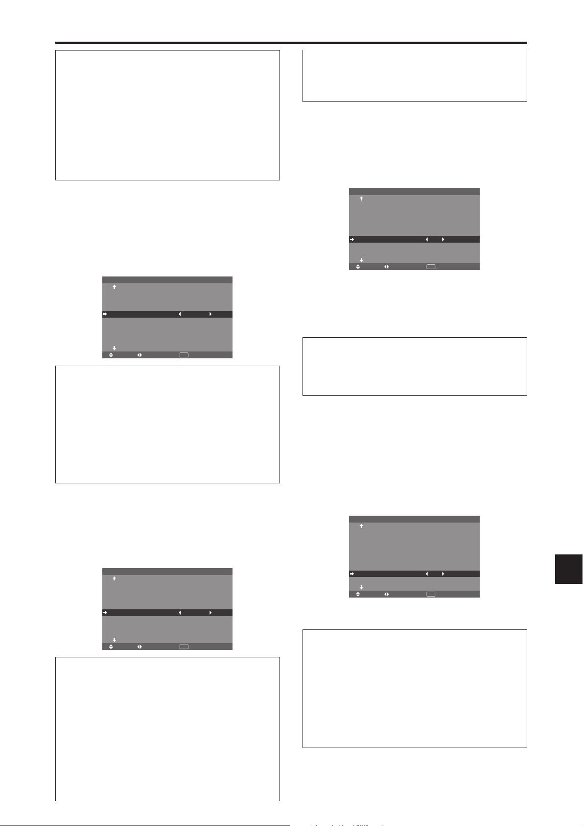
Informations
Réglage du VERROUILLAGE
MARCHE: Mise hors fonction des commandes du
panneau avant.
ARRET: Mise en fonction des commandes du panneau
avant.
* Quand la fonction VERROUILLAGE est active, le
bouton de commande POWER reste fonctionnel.
* Ce réglage prend effet dès que le menu en cours disparaît
de l’écran.
Mise en/hors fonction de la transmission des
télécommandes par câble
Cette fonction permet de mettre en/hors fonction la
transmission des télécommandes par câble.
Exemple : Réglage “ARRET”
Sur “IR REMOTE” dans le menu “OPTION3”, sélectionnez
“ARRET”, puis appuyez sur la touche MENU/ENTER.
OPTION3 3 / 4
PAGE
TIMER
POWER ON
VERROUILLAGE
IR REMOTE
MODE BOUCLE
ID CONNEXION
NUMERO ID
MUR D'IMAGE
PAGE
-
: ARRET
: ARRET
: ARRET
: ALL
: ALL
+
SEL. ADJ. RETOUR
EXIT
Informations
Réglage de IR REMOTE
MARCHE: Mise en fonction de la transmission des
télécommandes par câble.
ARRET: Mise hors fonction de la transmission des
télécommandes par câble.
Régler de préférence sur “ARRET” pour éviter toute
transmission d’une commande par un autre système de
télécommande.
Réglage du mode répétition
Cette fonction permet de mettre le signal en boucle de
répétition.
Exemple : Réglage “MARCHE”
Sur “MODE BOUCLE” dans le menu “OPTION3”,
sélectionnez “MARCHE”.
OPTION3 3 / 4
PAGE
TIMER
POWER ON
VERROUILLAGE
IR REMOTE
MODE BOUCLE
ID CONNEXION
NUMERO ID
MUR D'IMAGE
PAGE
-
: ARRET
: MARCHE
: MARCHE
: ALL
: ALL
+
SEL. ADJ. RETOUR
EXIT
Informations
Réglage du MODE BOUCLE (MODE
RÉPÉTITION)
MARCHE: Le signal reçu est mis en boucle via la borne
RGB1 ou la borne VIDEO1.
ARRET: Le signal reçu n’est pas mis en boucle.
* Même si MODE BOUCLE est réglé sur MARCHE
(ON) les signaux ne sont pas envoyés si l’alimentation
électrique (POWER) est coupée.
Raccordement à un autre écran d’affichage
Voir en page Fr-6.
Si le signal RGB1 est présent au moment de
la mise sous tension...
L’entrée RGB1 est affichée quel que soit le réglage du
MODE BOUCLE.
Régler le code à distance de la télécommande
Régler le code à distance pour adapter le moniteur plasma
à la télécommande.
Exemple: Régler sur “1”
Sur “ID CONNEXION” du menu “OPTION3”, sélectionner
“1”.
OPTION3 3 / 4
PAGE
TIMER
POWER ON
VERROUILLAGE
IR REMOTE
MODE BOUCLE
ID CONNEXION
NUMERO ID
MUR D'IMAGE
PAGE
-
: ARRET
: MARCHE
: ARRET
: 1
: ALL
+
SEL. ADJ. RETOUR
EXIT
• Maintenir la touche POWER ON appuyée puis relâcher
la touche lorsque le message indiquant que le code est
réglé s’affiche. Ou alors maintenir la touche POWER
STANDBY appuyée puis relâcher la touche lorsque
l’appareil s’éteint.
Informations
Réglage ID CONNEXION
ALL: Le code à distance n’est pas réglé.
1 à 4: Le code à distance spécifique est appliqué.
Réglage du numéro d’identification (Numéro
ID)
Si plusieurs écrans d’affichage sont utilisés en même
temps, cette fonction permet d’assigner un numéro d’ID
de sorte que les commandes à distance n’entraînent pas la
mise en route de plusieurs moniteurs simultanément.
Exemple : Réglage sur “2”
Sur “NUMERO ID” dans le menu “OPTION3”, sélectionnez
“2”.
OPTION3 3 / 4
PAGE
TIMER
POWER ON
VERROUILLAGE
IR REMOTE
MODE BOUCLE
ID CONNEXION
NUMERO ID
MUR D'IMAGE
PAGE
-
: ARRET
: MARCHE
: ARRET
: ALL
: 2
+
SEL. ADJ. RETOUR
EXIT
* Pour revenir au réglage ALL (tout)
Appuyer sur la touche CLEAR/SEAMLESS SW.
Informations
Réglage de NUMÉRO ID
ALL: Aucun numéro d’ID n’est assigné.
1 à 256: Un numéro d’ID est assigné.
Quand un numéro d’ID a été assigné
Il est alors possible d’assigner un NUMÉRO ID à
chaque télécommande pour assurer la commande
individuelle des divers écrans. Pour ce faire, voir page
Fr-34.
Fr-33

Pour assigner un numéro d’ID à la télécommande
Exemple : Réglage “2”
Appuyer sur le bouton ID SELECT de la télécommande.
L’écran “SÉLECT. ID” apparaît.
Sur “NUMERO ID” dans le menu “SÉLECT. ID”,
sélectionnez “2”.
L’écran “POSITION MUR D’IMAGE” apparaît.
Sur “POSITION NO.”, sélectionnez “4”.
POSITION MUR D'IMAGE
POSITION NO. 4
SÉ LECT. ID
POSITION : 1
NUMERO ID
ADJ. RETOUR
: 2
EXIT
* Pour revenir au réglage ALL (tout)
Appuyer sur la touche CLEAR/SEAMLESS SW.
Réglage du mur d’images
Cette fonction permet de configurer un mur d’image 22,
33, 44, 55, 51, 15.
Sur le menu “OPTION3”, sélectionnez “MUR D’IMAGE”,
puis appuyez sur la touche MENU/ENTER.
L’écran “MUR D’IMAGE” apparaît.
DECOUPAGE
POSITION
AFFICHAGE
AUTO ID
TRAME
ON. DIFFÉR É
PLE LINK
SEL. ADJ. RETOUR
Remarque:
MUR D'IMAGE
: ARRET
: SPRIT
: ARRET
: ARRET
: ARRET
EXIT
utiliser une méthode appropriée de mise
hors tension en cas d’urgence pendant la mise en place
d’un mur d’images.
DECOUPAGE
Réglage d’un mur d’images.
Exemple : Réglage “22”
Sur “DECOUPAGE” dans le menu “MUR D’IMAGE”,
sélectionnez “22”.
DECOUPAGE
POSITION
AFFICHAGE
AUTO ID
TRAME
ON. DIFFÉR É
PLE LINK
SEL. ADJ. RETOUR
MUR D'IMAGE
: 2 2
: SPRIT
: ARRET
: ARRET
: ARRET
EXIT
ADJ. RETOUR
EXIT
Informations
Réglage de POSITION MUR D’IMAGE
1 écran: Un positionnement n’est pas nécessaire.
22 écrans 33 écrans
NO. 1
NO. 4
NO. 2
NO. 3
NO. 7
NO. 10
NO. 13
NO. 8
NO. 11
NO. 14
NO. 9
NO. 12
NO. 15
44 écrans 55 écrans
NO. 16 NO. 17 NO. 18 NO. 19
NO. 20 NO. 21 NO. 22 NO. 23
NO. 24 NO. 25 NO. 26 NO. 27
NO. 28 NO. 29 NO. 30 NO. 31
NO. 32 NO. 33 NO. 34 NO. 35 NO. 36
NO. 37 NO. 38 NO. 39 NO. 40 NO. 41
NO. 42 NO. 43 NO. 44 NO. 45 NO.46
NO. 47 NO. 48 NO. 49 NO. 50 NO. 51
NO. 52 NO. 53 NO. 54 NO. 55 NO. 56
51 écrans 15 écrans
NO. 1 NO. 2 NO. 3 NO. 4 NO. 5
NO. 1
NO. 2
NO. 3
NO. 4
NO. 5
AFFICHAGE
Permet de choisir l’une des deux options (séparation,
blanc) pour le mode écran.
Exemple: Regler “BLANC”
Sur “AFFICHAGE” dans le menu “MUR D’IMAGE”,
sélectionnez “BLANC”.
DECOUPAGE
POSITION
AFFICHAGE
AUTO ID
TRAME
ON. DIFFÉR É
PLE LINK
SEL. ADJ. RETOUR
MUR D'IMAGE
: 1
: BLANC
: ARRET
: ARRET
: ARRET
EXIT
Informations
Réglage du DECOUPAGE
ARRET, 1: 1 écran (la fonction d’affichage de la matrice
est inactive)
22: 4 écrans
33: 9 écrans
44: 16 écrans
55: 25 écrans
51: 5 écrans horizontalement
15: 5 écrans verticalement
* Après avoir sélectionné 2×2, 3×3, 4×4, 5×5, 5×1, 1×5,
régler la POSITION MUR D’IMAGE.
POSITION MUR D’IMAGE
Permet de régler la position de chaque affichage.
Exemple : Réglage “4”
Sur le menu “MUR D’IMAGE”, sélectionnez “POSITION”,
puis appuyez sur la touche MENU/ENTER.
Informations
Réglage de l’AFFICHAGE
SPRIT (séparation): Permet de combiner des écrans
agrandis et de créer plusieurs écrans.
BLANC: Permet de corriger l’alignement de la partie des
écrans en combinaison et de créer des écrans multiples.
AUTO ID
Cette fonction permet d’assigner automatiquement un
numéro d’ID aux divers écrans connectés les uns aux
autres.
Exemple : Réglage “MARCHE”
Entrez un numéro d’ID (identification) pour le Moniteur
n°1 au menu NUMERO ID (Numéro d’identification).
Sur “AUTO ID” dans le menu “MUR D’IMAGE”,
sélectionnez “MARCHE”.
Fr-34
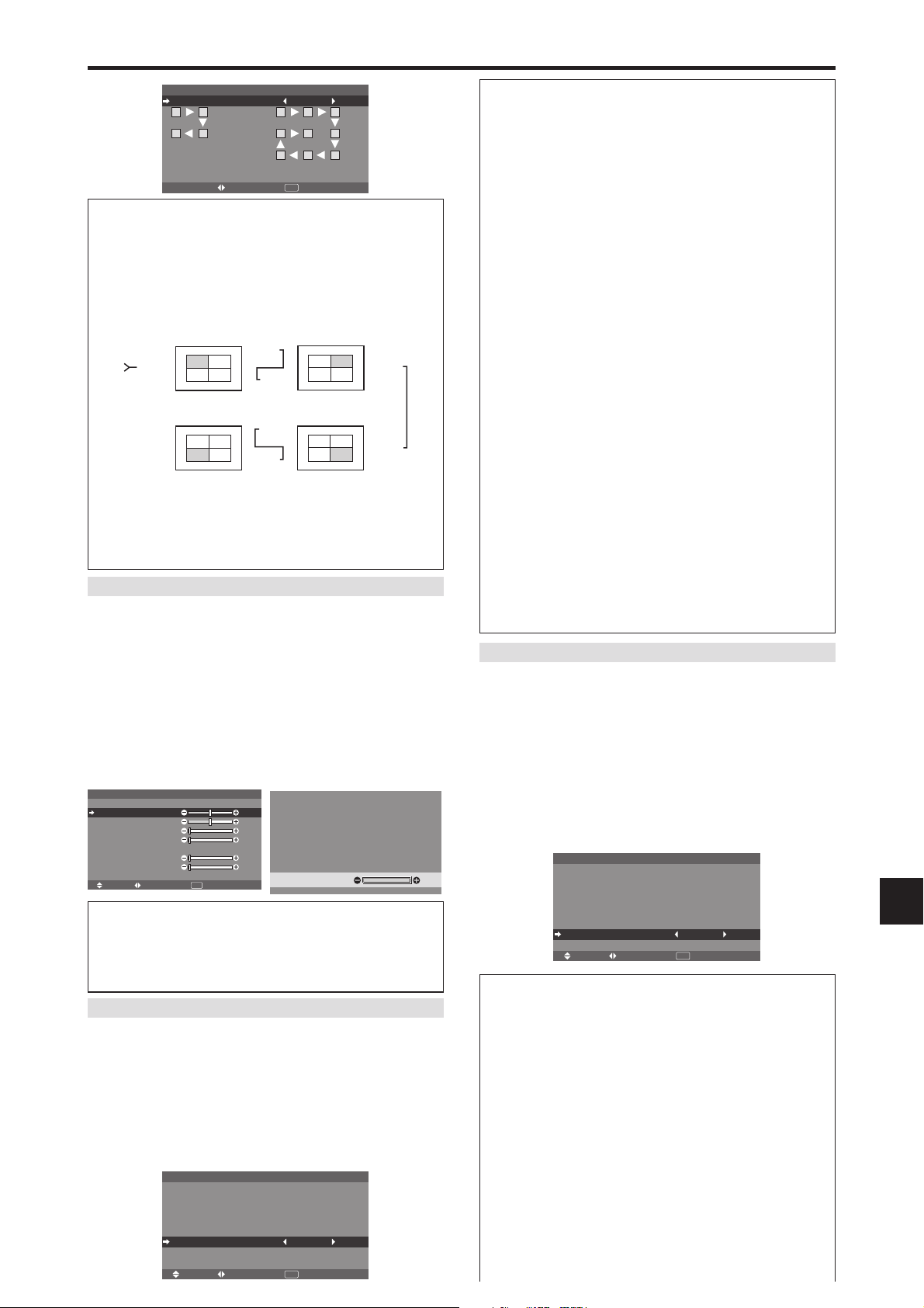
AUTO ID : MARCHE
1
4
AUTO ID
2
3
CONNECTION EN SÉRIE
DES MONITEURS
ADJ. RETOUR
1
8
7
EXIT
2
3
9
4
5
6
Informations
Réglage de AUTO ID
MARCHE: La fonction Auto ID est active. Dans le cas
suivant, l’affichage 1 prend le numéro d’identification 1,
l’affichage 2 le numéro d’identification 2 etc.
Cette option ne peut être configurée que lorsqu’un mur
vidéo 22, 33, 15 ou 51 est utilisé.
REMOTE
REMOTE
REMOTE
OUT
No.2
No.3No.4
No.2
No.3No.4
OUT
REMOTE
REMOTE
REMOTE
IN
No.1
IN
Display 1
No.1
Display 4
OUT
IN
No.1
No.2
Display 2
No.1
No.2
No.3No.4
Display 3
REMOTE
OUT
No.3No.4
REMOTE
IN
ARRET: La fonction Auto ID est inactive.
Remarque:
Pour utiliser cette fonction, vous devez
connecter les affichages avec le câble de télécommande
(non fourni).
REGLAGE IMAGE
Il est possible de régler la position de l’image et d’en
corriger le scintillement.
Exemple: Réglage de la position verticale en mode
normal
Sur le menu “MUR D’IMAGE”, sélectionnez “TRAME”,
puis appuyez sur la touche MENU/ENTER.
L’écran “REGLAGE IMAGE” apparaît.
Sur “V-POSITION” dans le menu “REGLAGE IMAGE”,
réglez la position.
REGLAGE IMAGE
MODE
V-POSITION
H-POSITION
V-HAUTEUR
H-LARGEUR
RÉ GLAGE AUTO
RÉ G FIN
RÉ G. IMAGE
UNDERSCAN
SEL. ADJ. RETOUR
: NORMAL
: ARRET
: ARRET
EXIT
: ±0
: ±0
: 0
: 0
: 0
: 0
V-POSITION
:
+
64
Informations
Réglage de REGLAGE IMAGE
Cette fonction a les mêmes effets qu’au menu
REGLAGE IMAGE de la page Fr-23.
ON DIFFÉRÉ (Mise sous tension différée)
Utiliser cette fonction pour activer la mise sous tension
différée.
Activer la fonction AUTO ID avant de procéder aux
opérations suivantes.
Exemple : Réglage “MARCHE”
Sur “ON. DIFFÉRÉ” dans le menu “MUR D’IMAGE”,
sélectionnez “MARCHE”.
DECOUPAGE
POSITION
AFFICHAGE
AUTO ID
TRAME
ON. DIFFÉR É
PLE LINK
SEL. ADJ. RETOUR
MUR D'IMAGE
: 1
: SPRIT
: ARRET
: MARCHE
: ARRET
EXIT
Informations
Réglage de ON DIFFÉRÉ
(Modes de mur d’image autres que 44 ou 55)
MARCHE: Chaque affichage est mis sous tension au bout
d’un certain délai.
* Une fois que cette fonction a été réglée sur “MARCHE”,
la touche POWER ON/OFF de la télécommande ne
fonctionne pas sauf pour le moniteur n°1.
En appuyant sur la touche POWER ON de la
télécommande, le moniteur n°1 s’allumera et les autres
s’allumeront automatiquement un par un.
* A partir du second moniteur, ni la touche POWER sur
l’unité ni la touche POWER ON de la télécommande
ne fonctionnent. Toutefois, en maintenant appuyée la
touche POWER ON pendant plus de 3 secondes, le
moniteur s’allumera.
ARRET: Tous les affichages sont mis sous tension au
même moment.
(Uniquement pour 44 et 55 écrans)
MODE1: Active l’alimentation principale de chaque
affichage différé.
MODE2: Active l’alimentation principale de chaque
affichage plus différé.
ARRET: Tous les affichages sont mis sous tension au
même moment.
Remarque:
Pour utiliser cette fonction, vous devez
connecter les affichages avec le câble de télécommande
(non fourni).
PLE LINK
Utiliser cette fonction pour régler chaque affichage selon
une luminosité uniforme.
Activer AUTO ID et régler le DECOUPAGE (sur 1, 22,
33, 15 ou 51) avant de procéder aux opérations
suivantes.
Exemple : Réglage “MARCHE”
Sur “PLE LINK” dans le menu “MUR D’IMAGE”,
sélectionnez “MARCHE”, puis appuyez sur la touche
MENU/ENTER.
DECOUPAGE
POSITION
AFFICHAGE
AUTO ID
TRAME
ON. DIFFÉR É
PLE LINK
SEL. ADJ. RETOUR
MUR D'IMAGE
: 1
: SPRIT
: ARRET
: ARRET
: MARCHE
EXIT
Informations
Réglage de PLE LINK
MARCHE: Chacun des écrans composant le mur d’images
est réglé selon une luminosité uniforme. Cette option ne
peut être configurée que lorsqu’un mur vidéo 1, 22,
33, 15 ou 51 est utilisé.
ARRET: La luminosité des écrans composant le mur
d’images doit être réglé de manière individuelle.
* Quand cette fonction est active (“MARCHE”), raccorder
les écrans à plasma à l’aide du câble de télécommande
(fourni en option) en respectant l’ordre des numéros de
position sur le mur d’images 22. Voir le schéma cidessous.
* En cas de modification des fonctions DÉCOUPAGE
ou POSITION, la fonction PLE est automatiquement
Fr-35
désactivée (ARRET).
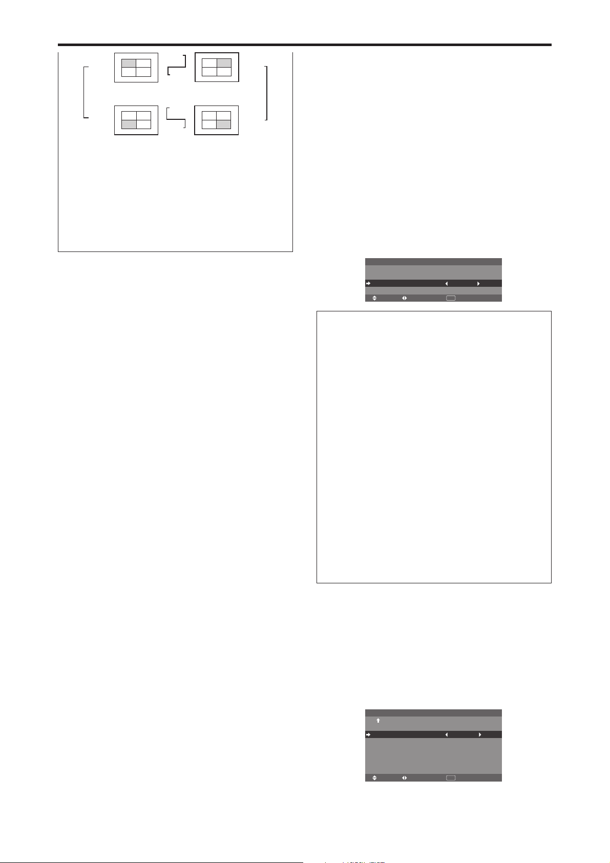
REMOTE
REMOTE
REMOTE
OUT
IN
No.1
No.2
No.3No.4
Display 1
No.1
No.2
No.3No.4
Display 4
OUT
REMOTE
REMOTE
REMOTE
IN
OUT
No.1
No.2
REMOTE
OUT
No.3No.4
IN
Display 2
No.1
No.2
REMOTE
No.3No.4
IN
Display 3
* Pour les murs d’image 33, 15 ou 51, raccorder
le dernier affichage au premier de la même manière que
pour un mur d’images 22.
Remarque:
* La télécommande peut ne pas fonctionner si le mode IR
REMOTE est désactive (ARRET).
* Pour utiliser cette fonction, vous devez connecter les
affichages avec le câble de télécommande (non fourni).
Menu des réglages de OPTION4
Régler “OSM AVANCÉ” sur “MARCHE” dans le MENU
PRINCIPAL.
Effacement de l’image de l’écran secondaire
lorsqu’il n’y a pas de signal d’entrée
Cette fonction efface automatiquement la cadre noir de
l’écran secondaire lorsqu’il n’y a pas de signal d’entrée
sur l’écran secondaire.
Cette fonction est disponible seulement lorsque le mode
image dans l’image est sélectionné.
Exemple : Réglage “AFFICHAGE” sur “FONDU”
Sur “2EME SOURCE” dans le menu “OPTION4”, puis
appuyez sur la touche MENU/ENTER.
L’écran “2EME SOURCE” apparaît.
Réglez les éléments.
DETECTION
TRANSPARENCE
AFFICHAGE
Informations
Fonction 2EME SOURCE
* La perte du signal d’entrée signifie une condition dans
laquelle le signal vidéo et le signal synchro ne sont pas
présents.
* Dans des conditions dans lesquelles l’écran secondaire
a disparu, les fonctions ZOOM NAVIG, GEL IMAGE,
et SEAMLESS SW ne fonctionneront pas. La touche
WIDE ne marchera pas non plus.
Réglages DETECTION
AUTO: Le cadre noir sans entrée de signal disparaît 3
secondes après la perte du signal d’entrée.
ARRET: Le cadre noir sans signal d’entrée est affiché de
manière constante.
Réglage TRANSPARENCE
Réglez la transparence de l’écran auxiliaire.
Réglage AFFICHAGE
NORMAL: L’écran auxiliaire est affiché de la même
manière.
FONDU: Le sous-écran s’ouvre en fondu.
2EME SOURCE
SEL. ADJ. RETOUR
: AUTO
: 100%
: FONDU
EXIT
Affichage de l’image en entier lors du
fonctionnement du DIGITAL ZOOM
Utilisez cette fonction pour afficher l’image en entier sur
l’écran secondaire avec une image agrandie sur l’écran
principal.
Exemple : Réglage “ZOOM NAVIG” à “CT A CT”
Sur “ZOOM NAVIG” dans le menu “OPTION4”,
sélectionnez “CT A CT”.
OPTION4 4 / 4
-
: CT A CT
: CT A CT1
: ARRET
: —
: —
: ARRET
SEL. ADJ. RETOUR
EXIT
Fr-36
PAGE
2EME SOURCE
ZOOM NAVIG
GEL IMAGE
SEAMLESS SW
SÉLECT 1
SÉLECT 2
AFFICH. TEXT

Informations
Fonction ZOOM NAVIG
* Cette fonction ne marche pas en mode d’écran multi.
* Cette fonction ne marche pas lorsque la fonction GEL
IMAGE est active.
* Le fait d’avoir un affichage à double écran annulera
cette fonction.
Réglages ZOOM NAVIG
ARRET: Ne montre pas l’image en entier sur l’écran
secondaire.
CT A CT: Montre l’image en entier sur l’écran secondaire
en mode côte à côte.
BAS GCH~HT GCH: Montre l’image en entier sur
l’écran secondaire en mode image dans l’image.
Côte-a-Côte Image-dans-Image
RGB1
bouton POINTER
et
bouton Zoom+/-
RGB1
Réglages GEL IMAGE
ARRET: Ne montre pas l’image fixe.
CT A CT1, 2: En appuyant sur la touche SELECT/
FREEZE, les images en pause capturées apparaissent sur
l’écran secondaire du mode côte à côte.
BAS GCH~HT GCH: Les images fixes capturées en
appuyant sur la touche SELECT/FREEZE apparaît sur
l’écran secondaire du mode image dans l’image.
Côte-a-Côte Image-dans-Image
CT A CT1
RGB1
RGB1
bouton
SELECT/
FREEZE
RGB1
RGB1
RGB1
bouton
SELECT/
FREEZE
RGB1
ou
CT A CT2
RGB1
RGB1
bouton POINTER
Affichage d’images fixes sur l’écran
secondaire
Cette fonction permet d’afficher sur l’écran secondaire des
images fixes capturées en appuyant sur la touche SELECT/
FREEZE.
Exemple : Réglage “GEL IMAGE” sur “BAS GCH”
Sur “GEL IMAGE” dans le menu “OPTION4”, sélectionnez
“BAS GCH”.
OPTION4 4 / 4
PAGE
2EME SOURCE
ZOOM NAVIG
GEL IMAGE
SEAMLESS SW
SÉLECT 1
SÉLECT 2
AFFICH. TEXT
-
: BAS GCH
: BAS GCH
: ARRET
: —
: —
: ARRET
SEL. ADJ. RETOUR
EXIT
Informations
Fonction GEL IMAGE
* Cette fonction ne marche pas en mode d’écran multi.
* Le zoom numérique n’est pas disponible lorsque cette
fonction est active.
* Si l’on appuie de nouveau sur la touche SELECT/
FREEZE alors que cette fonction est active, cette
fonction sera annulée.
* Le fait d’avoir un affichage à double écran annulera
cette fonction.
Commutation rapide de la source d’entrée
Cette fonction permet la sélection rapide de la source d’entrée.
Après avoir mis sur MARCHE, appuyez sur la touche
CLEAR/SEAMLESS SW pour commuter rapidement
entre les deux signaux d’entrée sélectionnés.
Exemple : Réglez pour commuter rapidement entre
RGB1 et RGB2
Sur “SEAMLESS SW” dans le menu “OPTION4”,
sélectionnez “MARCHE”.
Sélectionner “RGB1” et “RGB2”.
OPTION4 4 / 4
PAGE
2EME SOURCE
ZOOM NAVIG
GEL IMAGE
SEAMLESS SW
SÉLECT 1
SÉLECT 2
AFFICH. TEXT
-
: BAS GCH
: CT A CT1
: MARCHE
: RGB1
: RGB2
: ARRET
SEL. ADJ. RETOUR
EXIT
* Les sources disponibles dépendent des réglages de l’entrée.
Informations
Fonction SEAMLESS SW
* Cette fonction ne marche pas pour certaines
combinaisons d’entrée. Voir le tableau à la page Fr-16.
* Après avoir commuté sur l’entrée sélectionnée, veuillez
activer cette fonction.
* Cette fonction ne marche pas en mode d’écran multi.
* Lorsque SEAMLESS SW est activé en premier, ou
lorsque les signaux transmis sont modifiés, il peut y avoir
un bref délai à cause de l’analyse du signal.
Fr-37

Réglages SEAMLESS SW
ARRET: Désactive la fonction SEAMLESS SW.
MARCHE: Lorsque la touche CLEAR/SEAMLESS SW
est enfoncée, les signaux d’entrée commutent rapidement
suivant le réglage de SÉLECT1 et SÉLECT2.
Affichage de l’information comme un texte
Exemple : Réglage “AFFICH. TEXT” sur “BAS-3”,
“ENTREE” sur “RGB1”, “DETECTION” sur “AUTO”,
“TRSPARENCE” sur “100%” et “AFFICHAGE” sur
“NORMAL”
Sur “AFFICH. TEXT” dans le menu “OPTION4”,
sélectionner “BAS-3”, puis appuyez sur la touche MENU/
ENTER.
L’écran “AFFICH. TEXT” apparaît.
Réglez les éléments.
ENTREE
DETECTION
TRSPARENCE
AFFICHAGE
AFFICH. TEXT
: RGB1
: AUTO
: 100%
: NORMAL
SEL. ADJ. RETOUR
EXIT
Enhanced split screen Model
Informations
Réglage AFFICH. TEXT
ARRET: N’affiche aucun texte.
BAS-1 / BAS-2 / BAS-3 / 1/2 INF. / 1/2 SUP. / HT3 / HT-2 / HT-1 / GAUCHE / DROITE: Affiche un
texte à l’endroit spécifié, où les suffixes -1, -2 et -3
indiquent la hauteur de la zone de texte.
Réglage ENTREE
Règle l’entrée de texte sur le RGB 1 à 3.
Réglages DETECTION
AUTO: Le cadre noir sans entrée de signal disparaît 3
secondes après la perte du signal d’entrée.
ARRET: Le cadre noir sans signal d’entrée est affiché
de manière constante.
Réglage TRSPARENCE
Règle la transparence du texte.
Réglage AFFICHAGE
NORMAL: L’écran auxiliaire est affiché de la même
manière.
FONDU: Le sous-écran s’ouvre en fondu.
Menu des réglages de OSM Avancé
Passage au mode menu
Cette fonction permet d’accéder à toutes les rubriques du
menu.
Si ON. DIFFÉRÉ ou PLE LINK est réglé sur MARCHE
(ON), cette fonction reste active.
Exemple : Réglage “MARCHE”
Sur “OSM AVANCÉ” dans le menu “MENU PRINCIPAL”,
sélectionnez “MARCHE”.
MENU PRINCIPAL 1 / 2
IMAGE
AUDIO
REGLAGE IMAGE
OPTION1
OSM AVANCÉ
PAGE
SEL.
: ARRET
+
ADJ.
EXIT
EXIT
MENU PRINCIPAL 1 / 2
IMAGE
AUDIO
REGLAGE IMAGE
OPTION1
OPTION2
OPTION3
OPTION4
OSM AVANCÉ
PAGE
SEL.
+
: MARCHE
ADJ.
EXIT
EXIT
Informations
Réglage de OSM AVANCÉ
MARCHE: Toutes les rubriques du menu principal sont
accessibles.
ARRET: Certaines rubriques du menu principal ne sont
pas accessibles (OPTION2, OPTION3, OPTION4 par
exemple).
Menu des réglages de LANGAGE
Sélection de la langue des menus
Les menus sont disponibles en huit langues différentes.
Exemple: sélection des menus en “DEUTSCH”
Sur le MENU PRINCIPAL, sélectionner “LANGAGE”, puis
appuyer sur la touche MENU/ENTER.
L’écran “LANGAGE” apparaît.
Sur le menu “LANGAGE”, sélectionnez “DEUTSCH”, puis
appuyez sur la touche MENU/ENTER.
LANGAGE
LANGAGE
MENU/ENTER
ADJ.
“LANGAGE” est réglé sur “DEUTSCH” et retourne au menu
principal.
OK
: DEUTSCH
EXIT
RETOUR
Informations
Sélection de la langue des menus
ENGLISH .......... anglais
DEUTSCH ........ allemand
FRANÇAIS ....... français
ESPAÑOL .........espagnol
ITALIANO ......... italien
SVENSKA ........ suédois
У.............. russe
PORTUGUÊS ... portugais
Fr-38

Menu des réglages de TV SYSTÈMES
Sélection du format du signal vidéo
Pour paramétrer le code chromatique des signaux vidéo
composites ou des signaux d’entrée Y/C.
Exemple : Paramétrage du code chromatique sur
“3.58 NTSC”
Sur le MENU PRINCIPAL, sélectionner “TV SYSTÈMES”,
puis appuyer sur la touche MENU/ENTER.
L’écran “TV SYSTÈMES” apparaît.
Sur le menu “TV SYSTÈMES”, sélectionnez “3.58NTSC”.
TV SYSTÈMES
TV SYSTÈMES
ADJ.
Informations
Format de signaux de télévision couleur
Les signaux vidéo ont un format différent suivant les
pays. Paramétrez sur le code chromatique en usage dans
votre pays.
AUTO: Les codes chomatiques sont identifiés
automatiquement et le format est paramétré en
conséquence.
PAL: Ce standard est principalement utilisé au Royaume
Uni et en Allemagne.
SECAM: Ce standard est principalement utilisé en France
et en Russie.
4.43 NTSC, PAL60: Ce format est utilisé pour la vidéo
dans les pays utilisant les signaux vidéo PAL.
3.58 NTSC: C’est le format standard principalement
utilisé aux Etats-Unis et au Japon.
PAL-M: C’est le format standard utilisé principalement
au Brésil.
PAL-N: C’est le format standard utilisé principalement
en Argentine.
: 3.58NTSC
EXIT
RETOUR
Menu des réglages de SIGNAL
INFORMATION
Vérification des fréquences, polarités des
signaux d’entrée, et de la résolution
Utiliser cette fonction pour vérifier les fréquences et les
polarités des signaux envoyés par l’ordinateur, etc.
Sur le “MENU PRINCIPAL”, sélectionner “SIGNAL
INFORMATION”, puis appuyer sur la touche MENU/
ENTER.
Le “SIGNAL INFORMATION” est affichée.
SIGNAL INFORMATION
FRÉQ. H
FRÉQ. V
POL. H
POL. V
MEMOIRE
RÉ SOLUTION
PC: affichage de la MÉMOIRE.
Autres: affichage du MODE.
: 48.4KHZ
: 60.0HZ
: NÉG.
: NÉG.
: 24
×
768
: 1024
EXIT
RETOUR
Fr-39
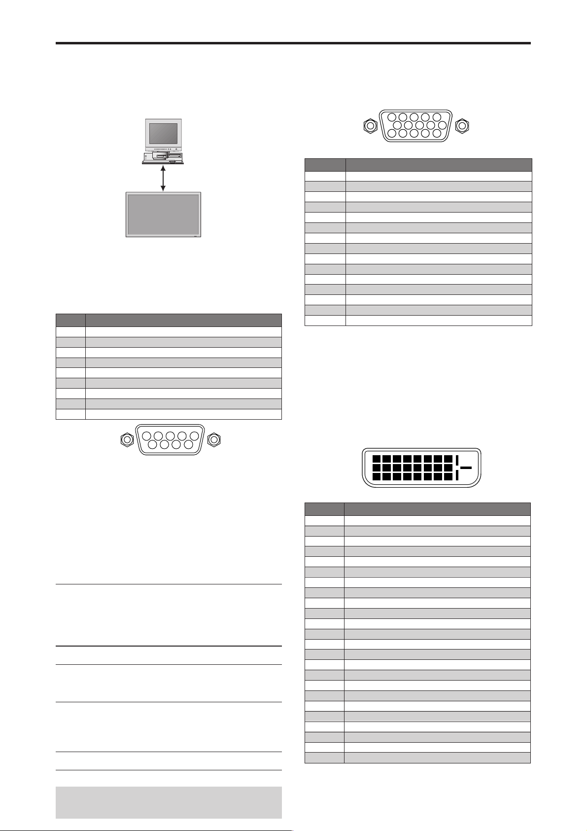
iteu
a
Commande Externe
Fonctions des broches
Application
Ces spécifications concernent la commande de
communications du moniteur à plasma par un appareil externe.
Connexions
Les connexions se font comme décrit ci-dessous.
Appareil externe
p. ex. Ordinateur
n
r
plasm
Connecteur sur le côté du moniteur à plasma :
Connecteur de la commande extérieure (EXTERNAL
CONTROL).
Utiliser un câble croisé (inversé).
Type de connecteur: D-Sub à 9 broches mâle
o
N
Pas de connexion
1
RXD (Réception des données)
2
TXD (Transmission des données)
3
DTR (Côté DTE prêt)
4
GND
5
DSR (Côté DCE prêt)
6
RTS (Prêt à envoyer)
7
CTS (Effacer pour envoyer)
8
Pas de connexion
9
Nom de broche
Connecteur mini D-sub à 15 broches
(analogique)
RGB 1
5 4 3 2 1
10 9 8 7 6
15 14 13 12 11
Broche n°
1
2
3
4
5
6
7
8
9
10
11
12
13
14
15
Rouge
VERT ou Sync. sur Vert
BLEU
Libre
Mise à la terre
Rouge mis à la terre
Vert mis à la terre
Bleu mis à la terre
Libre
Mise à la terre du signal Sync
Libre
Données DATA b-directionnel (SDA)
Synchro horizontale ou synchro composite
Sync verticale
Horloge de données
Signal (Numérique)
Connecteur DVI-D à 24 broches
(numérique)
Cet appareil est équipé d’un type de connecteurs
fréquemment utilisés pour des branchements numériques.
(Cela ne peut pas être utilisé pour une entrée analogique.)
(TMDS ne peut être utilisé que pour un seul raccord.)
34
7
5
8
9
2
1
6
Paramètres de communication
(1) Système de communication Asynchrone
12345678
910111213141516
RGB 3
20191817 21 22 23 24
(2) Interface RS-232C
(3) Taux de baud 9600 bps
Fr-40
Broche n°
1
2
3
4
5
6
7
8
9
10
11
12
13
14
15
16
17
18
19
20
21
22
23
24
Données 2 – pour T.M.D.S
Données 2 + pour T.M.D.S
Protection des données 2 pour T.M.D.S 2 Shield
Libre
Libre
Horloge DDC
Données DDC
Libre
Données 1 – pour T.M.D.S
Données 1 + pour T.M.D.S
Protection des données 1 pour
Libre
Libre
Alimentation électrique (+5 V )
Mise à la terre
Détection de branchement immédiat
Données 0 – pour T.M.D.S
Données 0 + pour T.M.D.S
Protection des données 0 pour T.M.D.S
Libre
Libre
Protection de l’horloge pour T.M.D.S
Horloge + pour T.M.D.S
Horloge – pour T.M.D.S
(4) Longueur de donnée 8 bits
(5) Parité Impaire Odd
(6) Bit d’arrêt 1 bit
(7) Code de communication Hex
Codes de commande extérieure
Fonction Donnéss de code
Alimentation Allumee 9FH 80H 60H 4EH 00H CDH
Eteinte 9FH 80H 60H 4FH 00H CEH
Sélection d’entrée
Audio Muet Allumé 9FH 80H 60H 3EH 00H BDH
Mode Image NORMAL DFH 80H 60H OAH 01H 01H CBH
Mode Ecran STADIUM DFH 80H 60H 51H 01H 02H 13H
Réglage Auto MARCHE DFH 80H 60H 7FH 03H 03H 09H 00H 4DH
Mode Cinema MARCHE DFH 80H 60H C1H 01H 01H 82H
Video1 (BNC) DFH 80H 60H 47H 01H 01H 08H
Video2 (RCA) DFH 80H 60H 47H 01H 02H 09H
Video3 (S-Video) DFH 80H 60H 47H 01H 03H 0AH
DVD1/HD1 (RCA) DFH 80H 60H 47H 01H 05H 0CH
DVD2/HD2 (BNC) DFH 80H 60H 47H 01H 06H 0DH
RGB1 (mini Sub D à 15 broches)
RGB2 (5BNC) DFH 80H 60H 47H 01H 08H 0FH
RGB3 (DVI) DFH 80H 60H 47H 01H 0CH 13H
Eteint 9FH 80H 60H 3FH 00H BEH
CINEMA1 DFH 80H 60H OAH 01H 02H CCH
CINEMA2 DFH 80H 60H OAH 01H 03H CDH
DEFAUT DFH 80H 60H OAH 01H 04H CEH
CLAIR DFH 80H 60H OAH 01H 05H CFH
ZOOM DFH 80H 60H 51H 01H 03H 14H
NORMAL DFH 80H 60H 51H 01H 04H 15H
COMPLET DFH 80H 60H 51H 01H 05H 16H
UNDERSCAN DFH 80H 60H 51H 01H 08H 19H
14 : 9 DFH 80H 60H 51H 01H 09H 1AH
2.35 : 1 DFH 80H 60H 51H 01H 0AH 1BH
ARRET DFH 80H 60H 7FH 03H 03H 09H 01H 4EH
ARRET DFH 80H 60H C1H 01H 02H 83H
Remarque:
DFH 80H 60H 47H 01H 07H 0EH
le cas échéant, pour une liste complète
(Référence)
des Codes de commande extérieure, contacter le
concessionnaire.
Signal (Numérique)

Connexion avec STB
Mini prise stéréo 1/8 (non fournie)
pour REMOTE IN/OUT
Moniteur à plasma REMOTE IN
GND VDD (DC +3 V)DATA (DC +5 V)
Moniteur à plasma REMOTE OUT
GND DATA (C-MOS DC +5 V)
Voici un exemple de connexion de STB (Set-top Box,
Boîtier décodeur) utilisant les connecteurs REMOTE IN/
OUT du moniteur à plasma. Consultez votre revendeur
pour obtenir des informations sur la connexion et le
fonctionnement.
* Exemple de connexion
• Le STB possède le connecteur REMOTE IN.
• La fonction des broches du connecteur REMOTE IN
du STB est identique à celle du mini câble stéréo 1/8
connecté au connecteur REMOTE OUT (Fr-41).
• La fréquence de transmission de la télécommande du
STB est de 37,9 kHz (Typique).
Exemple de connexion: Connexion d’un STB
ECRAN PLASMA
Câble vidéo
IN
OUT
OUT
Câble
télécommande*
Télécommande du STB
Onde porteuse fHz : 37,9 kHz
(Typique)
IN
STB
* Le mini-câble stéréo 1/8 n’est pas fourni.
Fr-41
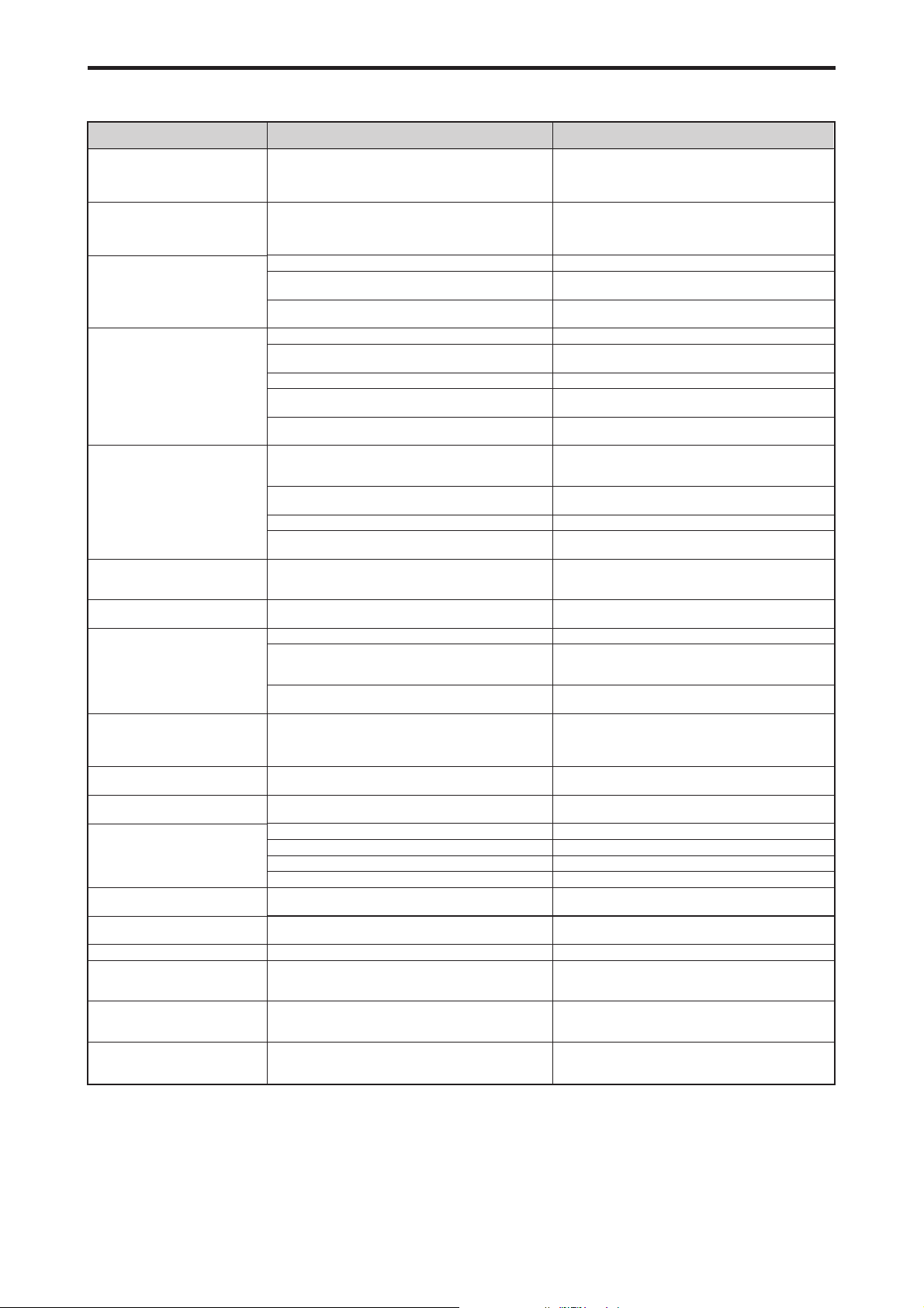
Dépannage
Si l’image est de qualité médiocre ou s’il existe un autre problème, vérifier les réglages, le fonctionnement, etc., avant
d’appeler le service après-vente.
Symptôme
L’appareil émet un bruit de
craquement.
L’image est déformée.
Le son est bruyant.
La télécommande fonctionne de
façon erronée.
La télécommande ne fonctionne
pas.
Le moniteur ne s’allume pas
lorsque l’on appuie sur la touche
marche de la télé-commande.
Le moniteur ne fonctionne pas
lorsque l’on appuie sur les touches
de la télécommand.
Les boutons du panneau avant de
l’appareil principal ne fonctionnent
pas.
Le moniteur ne produit aucun son
ou image.
L’image est présente mais il n’y a
pas de son.
Image de qualité médiocre avec
une entrée de signal VIDEO.
Image de qualité médiocre avec
une entrée de signal RGB.
La teinte n’est pas correcte et les
couleurs sont faibles.
Rien n’apparaît à l’écran.
Une partie de l’image n’est pas visible ou
l’image n’est pas centrée.
L’image est trop large ou trop petite.
L’image est instable.
L’indicateur ALLUME/VEILLE est
(POWER/STANDBY) s’allume en
rouge.
L’indicateur ALLUME/VEILLE
(POWER/STANDBY) clignote en et
rouge.
Le témoin ALIMENTATION/
ATTENTE clignote en vert et en
rouge, ou vert.
• L’image et le son sont-ils normaux ?
• Le composant connecté est-il placé directement devant
• Est-ce que les piles de la télécommande sont usagées ?
• Est-ce que la fonction IR REMOTE est réglée sur
• Est-ce que’un numéro d’ID a été assigné à l’unité
•
• Est-ce que les lampes témoins sont éteintes ?
• Est-ce que les piles de la télécommande sont usagées ?
• Est-ce que la fonction IR REMOTE est réglée sur
• Est-ce que’un numéro d’ID a été assigné à l’unité
• Est-ce que la télécommande est dirigée vers le moniteur
• Est-ce que le soleil ou une forte lumière éclaire le
• Est-ce que les piles de la télécommande sont usagées ?
• Le câble de commande est connecté dans la borne
• Les boutons du panneau avant ne fonctionnent pas
• Est-ce que le moniteur est raccordé au secteur ?
• Est-ce que le volume est réglé sur le minimum ?
• Est-ce que le volume est en sourdine ?
• Est-ce que les haut-parleurs sont raccordés
• L’entrée AUDIO INPUT est-elle effectuée correcte-ment
• Réglage des commandes inadapté.
• Réglage des commandes inadapté.
• Est-ce que la teinte et la couleur sont rég-lées
• Est-ce que l’ordinateur est en marche ?
• Est-ce qu’une source est connectée ?
• Est-ce que la gestion d’énergie est en veile ou sur arrêt ?
•
• Est-ce que le réglage de l’emplacement de l’image a été
• Est-ce que les réglages de dimension d’écrans ont été
• Est-ce que la résolution d’affichage est correcte ?
• Les signaux de synchronisation horizontale et/ou
• La température à l’intérieur de l’appareil principal est
Vérification
ou à côté de l’affichage?
MARCHE ?
principale ?
Est-ce que le moniteur est raccordé au secteur ?
ARRET ?
principale ?
ou y a-t-il un obstacle entre la télécommande et le
moniteur ?
capteur de la télécommande du moniteur ?
REMOTE IN (commande par câble).
lorsque le mode de verrouillage des commandes est
activé.
correctement ?
?
Interférence localisée.
Interconnexions des câbbles.
L’impédance en entrée n’est pas à un niveau correct.
Connexion incorrete sur connecteur à 15 broches.
correctement ?
Est-ce le MODE BOUCLE est réglé sur MARCHE ?
effectué ?
effectués ?
verticale ne sont pas présents lorsque le mode de
gestion de l’énergie est activé.
devenue trop élevée et cela a enclenché la sécurité de
protection.
———
• S’il n’y a pas d’anomalie dans l’image et le son ; le bruit
est causé par le boîtier réagissant à des changements
de température. Ceci n’affectera pas le bon
fonctionnement de l’appareil.
• Laisser un certain espace entre l’affichage et les
composants connectés.
• Remplacer les deux piles par des neuves.
• Régler IR REMOTE sur ARRET dans le menu
OPTION3.
• Assigner un numéro d’ID à l’aide de la touche ID
SELECT ou régler le numéro d’ID sur ALL.
• Brancher le câble d’alimentation au secteur.
• Appuyer sur la touche d’alimentation du moniteur pour
l’allumer.
• Remplacer les deux piles par des neuves.
• Régler IR REMOTE sur MARCHE dans le menu
OPTION3.
• Assigner un numéro d’ID à l’aide de la touche ID
SELECT ou régler le numéro d’ID sur ALL.
• Diriger la télécommande vers le capteur du moniteur en
appuyant sur la touche ou retirer l’obstacle.
• Éliminer la source de lumière en tirant les rideaux ou en
dirigeant la lumière dans une direction différente.
• Brancher le câble d’alimentation au secteur.
• Débrancher le câble de commande du moniteur.
• Régler le VERROUILLAGE sur ARRET.
• Remplacer les deux piles par des neuves.
• Augmenter le volume.
• Appuyer sur la touche sourdine de la télécommande.
• Raccorder les haut-parleurs correctement.
• Régler correctement AUDIO INPUT dans le menu
AUDIO.
• Ajuster les commandes de l’image est nécessaire.
Essayer un autre emplacement pour le moniteur.
S’assurer que tous les raccordements sont sûrs.
• Ajuster les commandes de l’image comme nécessaire.
Vérifier l’assignement des broches et les connexions.
• Régler la teinte et la couleur (Menu “IMAGE”).
• Mettre l’ordinateur en marche .
• Connecter une source au moniteur.
• Activer l’ordinateur (déplacer la souris, etc.).
• Régler le MODE BOUCLE sur ARRET.
• Ajuster “REGLAGE IMAGE” correctement.
• Appuyer sur la touche “WIDE” (écran large) de la
télécommande et régler cor-rectement les dimensions.
• Sélectionner la résolution d’affichage correcte.
• Vérifier le signal en entrée.
• Eteindre rapidement l’appareil principal et attendre que
la température interne se soit abaissée. Voir*1.
• Eteindre rapidement l’appareil principal. Voir *2.
Solution
*1 Protection anti-surchauffe
Si la température du moniteur devient excessive, la protection contre les surchauffes entrera en action et coupera l’alimentation. Dans ce cas, éteindre
l’appareil et débrancher le câble d’alimentation. Si la température de la pièce dans laquelle le moniteur est installé est particulièrement excessive,
déplacer l’appareil dans un endroit plus frais et le laisser refroidir 60 minutes. Si le problème persiste, prendre contact avec votre revendeur.
*2 Dans le cas suivant, éteindre immédiatement le moniteur et contacter un revendeur ou un centre agréé.
Le moniteur s’éteint 5 secondes après avoir été allumé et ensuite l’indicateur POWER/STANDBY clignote. Cela signifie que le circuit d’alimentation
électrique, la dalle d’affichage à plasma, le capteur de température ou un ventilateur au moins sont défectueux.
Fr-42
Tableau des signaux pris en charge par l’appareil
Résolutions compatible (42XM5)
• Quand le mode d’écran est NORMAL, tous les signaux sont convertis en signaux 768 points × 768 lignes. (Sauf pour *3 )
• Quand le mode d’écran est COMPLET, tous les signaux sont convertis en signaux 1024 points × 768 lignes.
Signaux d’entrée ordinateur pris en charge par ce système
Modèle
Type de signal
NEC PC-9800
Ordinateurs
compatibles
IBM PC/AT
Apple
Macintosh *
5
Points⳯lignes
640⳯400
720⳯400
640⳯480
720⳯400
848⳯480
852⳯480*
1
800⳯600
1024⳯768
1152⳯864
1280⳯768
1280⳯800*
1280⳯854
1280⳯960
1360⳯765
1360⳯768
1376⳯768
1280⳯1024
1400⳯1050*
1680⳯1050*
1600⳯1200
1920⳯1080*
1920⳯1200*
1920⳯1200RB
640⳯480
832⳯624
1024⳯768
1152⳯870
1440⳯900*
Fréquence
verticale
(Hz)
70,1
70,1
59,9
72,8
75,0
85,0
100,4
120,4
85,1
60,0
60,0
56,3
60,3
72,2
75,0
85,1
99,8
120,0
60,0
70,1
75,0
85,0
100,6
119,4
75,0
60,0
72,0
56,2
59,8
69,8
7
59,8
60,0
60,0
85,0
60,0
60,0
59,9
60,0
75,0
85,0
100,1
7
60,0
74,9
85,0
7
60,0
60,0
65,0
70,0
75,0
85,0
8
50,0
60,0
7
59,9
7
60,0
*
66,7
74,6
74,9
75,1
7
59,9
Fréquence
horizontale
(kHz)
31,5
31,5
31,5
37,9
37,5
43,3
51,1
61,3
37,9
31,0
31,7
35,2
37,9
48,1
46,9
53,7
63,0
75,7
48,4
56,5
60,0
68,7
80,5
95,5
67,5
53,7
64,9
45,1
48,0
56,0
49,7
53,1
60,0
85,9
47,7
47,7
48,3
64,0
80,0
91,1
108,5
65,3
82,3
93,9
65,3
75,0
81,3
87,5
93,8
106,3
56,2
67,5
74,6
74,0
35,0
49,7
60,2
68,7
55,9
Polarité synchro Présence Mode d’écran
Horizontale
Verticale
Horizontale
Verticale
NORMAL
COMPLET
(4:3)
NEG
NEG
NEG
NEG
NEG
NEG
NEG
NEG
NEG
POS
NEG
POS
POS
POS
POS
POS
POS
POS
NEG
NEG
POS
POS
NEG
NEG
POS
POS
POS
POS
POS
NEG
NEG
NEG
POS
POS
POS
POS
NEG
POS
POS
POS
POS
NEG
NEG
NEG
NEG
POS
POS
POS
POS
POS
POS
POS
NEG
NEG
Synchro sur V
Synchro sur V
Synchro sur V
Synchro sur V
NEG
NEG
NEG
NEG
NEG
NEG
NEG
NEG
NEG
POS
POS
NEG
POS
POS
POS
POS
POS
POS
POS
NEG
NEG
POS
POS
NEG
NEG
POS
NEG
NEG
POS
NEG
POS
POS
NEG
POS
POS
POS
POS
POS
POS
POS
POS
POS
POS
POS
POS
POS
POS
POS
POS
POS
POS
POS
POS
POS
POS
Synchro sur V
Synchro sur V
Synchro sur V
Synchro sur V
POS
OUI
OUI
OUI
OUI
OUI
OUI
OUI
OUI
OUI
OUI
OUI
OUI
OUI
OUI
OUI
OUI
OUI
OUI
OUI
OUI
OUI
OUI
OUI
OUI
OUI
OUI
OUI
OUI
OUI
OUI
OUI
OUI
OUI
OUI
OUI
OUI
OUI
OUI
OUI
OUI
OUI
OUI
OUI
OUI
OUI
OUI
OUI
OUI
OUI
OUI
OUI
OUI
OUI
OUI
– –
– –
– –
– –
OUI
OUI
OUI
OUI
OUI
OUI
OUI
OUI
OUI
OUI
OUI
OUI
OUI
OUI
OUI
OUI
OUI
OUI
OUI
OUI
OUI
OUI
OUI
OUI
OUI
OUI
OUI
OUI
OUI
OUI
OUI
OUI
OUI
OUI
OUI
OUI
OUI
OUI
OUI
OUI
OUI
OUI
OUI
OUI
OUI
OUI
OUI
OUI
OUI
OUI
OUI
OUI
OUI
OUI
OUI
– –
– –
– –
– –
OUI
– –
– –
OUI
OUI
OUI
OUI
OUI
OUI
– –
– –
– –
OUI
OUI
OUI
OUI
OUI
OUI
OUI
OUI
OUI
OUI
OUI
OUI
OUI
OUI
OUI
OUI
– –
– –
– –
– –
– –
OUI
OUI
– –
– –
– –
OUI*
OUI*
OUI*
OUI*
OUI
OUI
OUI
– –
OUI
OUI
OUI
OUI
OUI
– –
– –
– –
– –
OUI
OUI
OUI
OUI
– –
3
3
3
3
(16:9)
OUI*
OUI*
OUI*
OUI*
OUI*
OUI*
OUI*
OUI
OUI
OUI
OUI
OUI
OUI
OUI
OUI
OUI
OUI
OUI
OUI
OUI
OUI
OUI
OUI
OUI
OUI
OUI
OUI
OUI
OUI
OUI
OUI
OUI
OUI
OUI
OUI
OUI
OUI
OUI
OUI
OUI
OUI
OUI
OUI
OUI
OUI
OUI
OUI
OUI
OUI
OUI
OUI
OUI
OUI
OUI
OUI
OUI
OUI
OUI
OUI
SÉLECT
RGB *
– –
720⳯400
640⳯480
– –
– –
– –
– –
– –
– –
848⳯480
852⳯480
800⳯600
– –
– –
– –
– –
– –
– –
2
1024⳯768
2
1024⳯768
2
1024⳯768
2
– –
2
– –
2
– –
1152⳯864
1152⳯864
– –
1280⳯768
1280⳯768
1280⳯768
1280⳯800
1280⳯854
– –
– –
1360⳯765
1360⳯768
1376⳯768
1280⳯1024
– –
– –
– –
1400⳯1050
– –
– –
1680⳯1050
1600⳯1200
– –
– –
– –
– –
1920⳯1080
1920⳯1080
1920⳯1200
1920⳯1200RB
– –
– –
2
– –
– –
– –
DVI
NON
OUI
OUI
OUI
OUI
OUI
OUI
OUI
OUI
OUI
OUI
OUI
OUI
OUI
OUI
OUI
OUI
OUI
OUI
OUI
OUI
OUI
OUI
OUI
OUI
OUI
OUI
NON
OUI
OUI
OUI
OUI
OUI
OUI
NON
OUI
OUI
OUI
OUI
OUI
NON
OUI
OUI
NON
OUI
OUI
NON
NON
NON
NON
OUI
OUI
– –
OUI
NON
NON
NON
NON
OUI
AFFICH.
TEXT
OUI
OUI
OUI
OUI
OUI
OUI
OUI
OUI
OUI
OUI
OUI
OUI
OUI
OUI
OUI
OUI
OUI
OUI
OUI
OUI
OUI
OUI
9
OUI*
9
OUI*
OUI
OUI
OUI
OUI
OUI
OUI
OUI
OUI
OUI
9
OUI*
OUI
OUI
OUI
OUI
9
OUI*
9
OUI*
9
OUI*
9
OUI*
9
OUI*
9
OUI*
9
OUI*
9
OUI*
9
OUI*
9
OUI*
9
OUI*
9
OUI*
9
OUI*
9
OUI*
9
OUI*
9
OUI*
OUI
OUI
OUI
OUI
OUI
Memoire
4
82
5
7
8
9
41
42
73
19
17
11
12
13
14
15
43
44
24
25
26
27
45
46
51
84
85
52
80
66
21
37
63
64
22
22
53
29
30
40
47
131
71
72
38
54
55
56
57
58
111
110
81
88
6
16
28
39
89
4
Fr-43

Modèle
Type de signal
Work Station
(EWS4800)
Work Station (HP)
Work Station
(SUN)
Work Station
(SGI)
Points⳯lignes
1280⳯1024
1280⳯1024
1152⳯900
1280⳯1024
1024⳯768
1280⳯1024
Fréquence
verticale
(Hz)
60,0
71,2
72,0
66,0
76,0
76,1
60,0
60,0
Fréquence
horizontale
(kHz)
64,6
75,1
78,1
61,8
71,7
81,1
49,7
63,9
Polarité synchro Présence Mode d’écran
Horizontale
Verticale
Horizontale
Verticale
NORMAL
COMPLET
(4:3)
3
– –
– –
– –
– –
– –
– –
OUI*
OUI*
OUI*
OUI
OUI
OUI*
OUI
OUI*
3
3
3
3
NEG
NEG
– –
Synchro C
Synchro C
Synchro C
– –
– –
NEG
NEG
– –
Synchro C
Synchro C
Synchro C
– –
– –
OUI
OUI
– –
– –
– –
– –
– –
– –
OUI
OUI
(16:9)
OUI
OUI
OUI
OUI
OUI
OUI
OUI*
OUI
SÉLECT
RGB *
1280⳯1024
2
1024⳯768
1280⳯1024
4
– –
– –
– –
– –
– –
IDC-3000G
PAL625P
NTSC525P
768⳯576
640⳯480
50,0
59,9
31,4
31,5
NEG
NEG
NEG
NEG
OUI
OUI
OUI
OUI
OUI*
OUI*
6
6
OUI*
OUI*
6
– –
6
525P
*1 Uniquement en utilisant une carte graphique accélératrice capable d’afficher 852 × 480.
*2 L’image est affichée dans la résolution originale. L’image est comprimée pour d’autres signaux.
*3 Le format est 5/4. Ce signal est converti en signal 720 points × 768 lignes.
*4 Normalement, le mode de sélection RGB pour les signaux d’entrée est automatiquement sélectionné. Si l’image n’est pas
correctement affichée, activer le mode RGB préparé pour les signaux d’entrée indiqués dans le tableau ci-dessus.
*5 Pour raccorder le moniteur à un ordinateur Macintosh, utiliser l’adaptateur de moniteur fourni (D-Sub 15 broches) sur le port
vidéo de l’ordinateur.
*6 D’autres modes d’écran (ZOOM et STADIUM) sont également disponibles.
*7 Conforme à la norme CVT.
*8 Le signal analogique n’est pas disponible.
*9 Le texte ne peut pas être affiché à l’emplacement de “DROITE” et de “GAUCHE”.
DVI
OUI
OUI
OUI
OUI
OUI
OUI
OUI
OUI
NON
NON
AFFICH.
TEXT
9
OUI*
9
OUI*
9
OUI*
OUI
OUI
9
OUI*
9
OUI*
9
OUI*
9
OUI*
9
OUI*
Memoire
29
48
59
60
61
30
62
29
31
32
REMARQUE :
• Même si les signaux d’entrée sont conformes à la résolution indiquée dans le tableau ci-dessus, il pourra être nécessaire de
régler la position et le format de l’image ou le piqué en raison d’erreurs de synchronisation de l’ordinateur.
• Ce moniteur a une résolution de 1024 points × 768 lignes. Il est conseillé d’utiliser un signal d’entrée XGA, wide XGA ou
équivalent.
• Avec des entrées numériques certains signaux ne sont pas acceptés.
• La synchronisation peut être perturbée quand des signaux non standard autres que ceux mentionnés ci-dessus sont entrés.
• Pour connecter un signal à composantes, utilisez la borne HD.
Qu’est-ce que la technologie HDCP/HDCP ?
HDCP est un acronyme de High-bandwidth Digital Content Protection (protection de contenu numérique à large bande passante).
La protection de contenu numérique à large bande passante (HDCP) est un système destiné à empêcher la copie illégale de
données vidéo envoyées sur une interface visuelle numérique (DVI).
Si vous ne pouvez pas visionner un contenu via l’entrée DVI, cela ne signifie pas pour autant que le PDP ne fonctionne pas
correctement. Avec l’application du HDCP il se peut que, dans certains cas, un contenu soit protégé avec HDCP et ne puisse pas
être affiché en raison de la décision/intention de la communauté HDCP (Digital Content Protection, LLC).
•“IBM PC/AT” et “XGA” sont des marques déposées de International Business Machines, Inc., U.S.A.
•“Apple Macintosh” est une marque déposée par Apple Computer, Inc. U.S.A.
Fr-44

Modèle
Type de signal
NEC PC-9800
Ordinateurs
compatibles
IBM PC/AT
Apple
Macintosh *
5
Résolutions compatible (50XM6/60XM5)
• Quand le mode d’écran est NORMAL, tous les signaux sont convertis en signaux 1024 points × 768 lignes. (Sauf pour *
• Quand le mode d’écran est REELLE, l’image est affichée avec la résolution originale.
• Quand le mode d’écran est COMPLET, tous les signaux sont convertis en signaux 1365 points × 768 lignes. (Sauf pour *
Signaux d’entrée ordinateur pris en charge par ce système
Points⳯lignes
640⳯400
720⳯400
640⳯480
720⳯400
848⳯480
852⳯480*
1
800⳯600
1024⳯768
1152⳯864
1280⳯768
1280⳯800*
1280⳯854
1280⳯960
1360⳯765
1360⳯768
1376⳯768
1280⳯1024
1400⳯1050*
1680⳯1050*
1600⳯1200
1920⳯1080*
1920⳯1200*
1920⳯1200RB
*
640⳯480
832⳯624
1024⳯768
1152⳯870
1440⳯900*
Fréquence
verticale
(Hz)
70,1
70,1
59,9
72,8
75,0
85,0
100,4
120,4
85,1
60,0
60,0
56,3
60,3
72,2
75,0
85,1
99,8
120,0
60,0
70,1
75,0
85,0
100,6
119,4
75,0
60,0
72,0
56,2
59,8
69,8
7
59,8
60,0
60,0
85,0
60,0
60,0
59,9
60,0
75,0
85,0
100,1
7
60,0
74,9
85,0
7
60,0
60,0
65,0
70,0
75,0
85,0
8
50,0
60,0
7
59,9
7
60,0
66,7
74,6
74,9
75,1
7
59,9
Fréquence
horizontale
(kHz)
31,5
31,5
31,5
37,9
37,5
43,3
51,1
61,3
37,9
31,0
31,7
35,2
37,9
48,1
46,9
53,7
63,0
75,7
48,4
56,5
60,0
68,7
80,5
95,5
67,5
53,7
64,9
45,1
48,0
56,0
49,7
53,1
60,0
85,9
47,7
47,7
48,3
64,0
80,0
91,1
108,5
65,3
82,3
93,9
65,3
75,0
81,3
87,5
93,8
106,3
56,2
67,5
74,6
74,0
35,0
49,7
60,2
68,7
55,9
Polarité synchro Présence Mode d’écran
Horizontale
Verticale
Horizontale
Verticale
NORMAL
REELLE
(4:3)
NEG
NEG
NEG
NEG
NEG
NEG
NEG
NEG
NEG
POS
NEG
POS
POS
POS
POS
POS
POS
POS
NEG
NEG
POS
POS
NEG
NEG
POS
POS
POS
POS
POS
NEG
NEG
NEG
POS
POS
POS
POS
NEG
POS
POS
POS
POS
NEG
NEG
NEG
NEG
POS
POS
POS
POS
POS
POS
POS
NEG
NEG
Synchro sur V
Synchro sur V
Synchro sur V
Synchro sur V
NEG
NEG
NEG
NEG
NEG
NEG
NEG
NEG
NEG
POS
POS
NEG
POS
POS
POS
POS
POS
POS
POS
NEG
NEG
POS
POS
NEG
NEG
POS
NEG
NEG
POS
NEG
POS
POS
NEG
POS
POS
POS
POS
POS
POS
POS
POS
POS
POS
POS
POS
POS
POS
POS
POS
POS
POS
POS
POS
POS
POS
Synchro sur V
Synchro sur V
Synchro sur V
Synchro sur V
POS
OUI
OUI
OUI
OUI
OUI
OUI
OUI
OUI
OUI
OUI
OUI
OUI
OUI
OUI
OUI
OUI
OUI
OUI
OUI
OUI
OUI
OUI
OUI
OUI
OUI
OUI
OUI
OUI
OUI
OUI
OUI
OUI
OUI
OUI
OUI
OUI
OUI
OUI
OUI
OUI
OUI
OUI
OUI
OUI
OUI
OUI
OUI
OUI
OUI
OUI
OUI
OUI
OUI
OUI
– –
– –
– –
– –
OUI
OUI
OUI
OUI
OUI
OUI
OUI
OUI
OUI
OUI
OUI
OUI
OUI
OUI
OUI
OUI
OUI
OUI
OUI
OUI
OUI
OUI
OUI
OUI
OUI
OUI
OUI
OUI
OUI
OUI
OUI
OUI
OUI
OUI
OUI
OUI
OUI
OUI
OUI
OUI
OUI
OUI
OUI
OUI
OUI
OUI
OUI
OUI
OUI
OUI
OUI
OUI
OUI
OUI
OUI
– –
– –
– –
– –
OUI
– –
– –
OUI
OUI
OUI
OUI
OUI
OUI
– –
– –
– –
OUI
OUI
OUI
OUI
OUI
OUI
OUI
OUI*
OUI*
OUI*
OUI*
OUI*
OUI*
OUI
OUI
OUI
– –
– –
– –
– –
– –
OUI
OUI
– –
– –
– –
OUI*
OUI*
OUI*
OUI*
OUI
OUI
OUI
– –
OUI
OUI
OUI
OUI
OUI
– –
– –
– –
– –
OUI
OUI
OUI*
OUI
– –
OUI
OUI
OUI
OUI
OUI
OUI
OUI
OUI
OUI
OUI
OUI
OUI
OUI
OUI
OUI
OUI
OUI
OUI
2
– –
2
– –
2
– –
2
– –
2
– –
2
– –
– –
– –
– –
– –
– –
– –
– –
– –
– –
– –
– –
– –
– –
3
– –
3
– –
3
– –
3
– –
– –
– –
– –
– –
– –
– –
– –
– –
– –
– –
– –
– –
– –
OUI
OUI
2
– –
– –
– –
Fr-45
COMPLET
(16:9)
OUI
OUI
OUI
OUI
OUI
OUI
OUI
OUI
OUI
OUI
OUI
OUI
OUI
OUI
OUI
OUI
OUI
OUI
OUI
OUI
OUI
OUI
OUI
OUI
OUI
OUI
OUI
OUI
OUI
OUI
OUI
OUI
OUI
OUI
OUI*
OUI*
OUI
OUI
OUI
OUI
OUI
OUI
OUI
OUI
OUI
OUI
OUI
OUI
OUI
OUI
OUI
OUI
OUI
OUI
OUI
OUI
OUI
OUI
OUI
2
)
SÉLECT
RGB *
720⳯400
640⳯480
848⳯480
852⳯480
800⳯600
1024⳯768
1024⳯768
1024⳯768
1152⳯864
1152⳯864
1280⳯768
1280⳯768
1280⳯768
1280⳯800
1280⳯854
2
1360⳯765
2
1360⳯768
1376⳯768
1280⳯1024
1400⳯1050
1680⳯1050
1600⳯1200
1920⳯1080
1920⳯1080
1920⳯1200
1920⳯1200RB
– –
– –
– –
– –
– –
– –
– –
– –
– –
– –
– –
– –
– –
– –
– –
– –
– –
– –
– –
– –
– –
– –
– –
– –
– –
– –
– –
– –
– –
– –
– –
– –
– –
2, 3
)
DVI
NON
OUI
OUI
OUI
OUI
OUI
OUI
OUI
OUI
OUI
OUI
OUI
OUI
OUI
OUI
OUI
OUI
OUI
OUI
OUI
OUI
OUI
OUI
OUI
OUI
OUI
OUI
NON
OUI
OUI
OUI
OUI
OUI
OUI
NON
OUI
OUI
OUI
OUI
OUI
NON
OUI
OUI
NON
OUI
OUI
NON
NON
NON
NON
OUI
OUI
– –
OUI
NON
NON
NON
NON
OUI
AFFICH.
TEXT
OUI
OUI
OUI
OUI
OUI
OUI
OUI
OUI
OUI
OUI
OUI
OUI
OUI
OUI
OUI
OUI
OUI
OUI
OUI
OUI
OUI
OUI
9
OUI*
9
OUI*
OUI
OUI
OUI
OUI
OUI
OUI
OUI
OUI
OUI
9
OUI*
OUI
OUI
OUI
OUI
9
OUI*
9
OUI*
9
OUI*
9
OUI*
9
OUI*
9
OUI*
9
OUI*
9
OUI*
9
OUI*
9
OUI*
9
OUI*
9
OUI*
9
OUI*
9
OUI*
9
OUI*
9
OUI*
OUI
OUI
OUI
OUI
OUI
Memoire
4
82
5
7
8
9
41
42
73
19
17
11
12
13
14
15
43
44
24
25
26
27
45
46
51
84
85
52
80
66
21
37
63
64
22
22
53
29
30
40
47
131
71
72
38
54
55
56
57
58
111
110
81
88
6
16
28
39
89
4

Modèle
Type de signal
Work Station
(EWS4800)
Work Station (HP)
Work Station
(SUN)
Work Station
(SGI)
IDC-3000G
PAL625P
NTSC525P
*1 Uniquement en utilisant une carte graphique accélératrice capable d’afficher 852 × 480.
*2 L’image est affichée dans la résolution originale.
*3 Le ratio d’aspect est 5/4. Ce signal est converti en signal de 960 points × 768 lignes.
*4 Normalement, le mode de sélection RGB pour les signaux d’entrée est automatiquement sélectionné. Si l’image n’est pas
correctement affichée, activer le mode RGB préparé pour les signaux d’entrée indiqués dans le tableau ci-dessus.
*5 Pour raccorder le moniteur à un ordinateur Macintosh, utiliser l’adaptateur de moniteur (D-Sub 15 broches) sur le port
vidéo de l’ordinateur.
*6 D’autres modes d’écran (ZOOM et STADIUM) sont également disponibles.
*7 Conforme à la norme CVT.
*8 Le signal analogique n’est pas disponible.
*9 Le texte ne peut pas être affiché à l’emplacement de “DROITE” et de “GAUCHE”.
Points⳯lignes
1280⳯1024
1280⳯1024
1152⳯900
1280⳯1024
1024⳯768
1280⳯1024
768⳯576
640⳯480
Fréquence
verticale
(Hz)
60,0
71,2
72,0
66,0
76,0
76,1
60,0
60,0
50,0
59,9
Fréquence
horizontale
(kHz)
64,6
75,1
78,1
61,8
71,7
81,1
49,7
63,9
31,4
31,5
Polarité synchro Présence Mode d’écran
Horizontale
Verticale
Horizontale
Verticale
NORMAL
REELLE
(4:3)
3
NEG
NEG
– –
Synchro C
Synchro C
Synchro C
– –
– –
NEG
NEG
NEG
NEG
– –
Synchro C
Synchro C
Synchro C
– –
– –
NEG
NEG
OUI
OUI
– –
– –
– –
– –
– –
– –
OUI
OUI
OUI
OUI
– –
– –
– –
– –
– –
– –
OUI
OUI
OUI*
OUI*
OUI*
OUI
OUI
OUI*
OUI*
OUI*
OUI*
OUI*
– –
3
– –
3
– –
– –
– –
3
– –
2
– –
3
– –
6
– –
6
– –
COMPLET
(16:9)
OUI
OUI
OUI
OUI
OUI
OUI
OUI
OUI
6
OUI*
6
OUI*
SÉLECT
4
RGB *
1280⳯1024
– –
– –
– –
– –
– –
1024⳯768
1280⳯1024
– –
525P
DVI
OUI
OUI
OUI
OUI
OUI
OUI
OUI
OUI
NON
NON
AFFICH.
TEXT
9
OUI*
9
OUI*
9
OUI*
OUI
OUI
9
OUI*
9
OUI*
9
OUI*
9
OUI*
9
OUI*
Memoire
29
48
59
60
61
30
62
29
31
32
REMARQUE :
• Même si les signaux d’entrée sont conformes à la résolution indiquée dans le tableau ci-dessus, il pourra être nécessaire de
régler la position et le format de l’image ou le piqué en raison d’erreurs de synchronisation de l’ordinateur.
• Lorsqu’un signal de 1280 points × 1024 lignes ou de 1600 points × 1200 lignes est reçu par le moniteur, l’image est compressée.
• Ce moniteur a une résolution de 1365 points × 768 lignes. Il est recommandé d’utiliser un signal d’entrée XGA, wide-XGA ou
équivalent.
• Avec des entrées numériques certains signaux ne sont pas acceptés.
• La synchronisation peut être perturbée quand des signaux non standard autres que ceux mentionnés ci-dessus sont entrés.
• Pour connecter un signal à composantes, utilisez la borne HD.
Qu’est-ce que la technologie HDCP/HDCP ?
HDCP est un acronyme de High-bandwidth Digital Content Protection (protection de contenu numérique à large bande passante).
La protection de contenu numérique à large bande passante (HDCP) est un système destiné à empêcher la copie illégale de
données vidéo envoyées sur une interface visuelle numérique (DVI).
Si vous ne pouvez pas visionner un contenu via l’entrée DVI, cela ne signifie pas pour autant que le PDP ne fonctionne pas
correctement. Avec l’application du HDCP il se peut que, dans certains cas, un contenu soit protégé avec HDCP et ne puisse pas
être affiché en raison de la décision/intention de la communauté HDCP (Digital Content Protection, LLC).
•“IBM PC/AT” et “XGA” sont des marques déposées de International Business Machines, Inc., U.S.A.
•“Apple Macintosh” est une marque déposée par Apple Computer, Inc. U.S.A.
Fr-46

Caractéristiques
䡵 42XM5
Dimensions de l’écran 36,3 pouces(H)⳯20,3 pouces(V)
Rapport largeur/hauteur 16 / 9
Résolution 1024 pixels(H) ⳯768 pixels(V)
Pixel Pitch 0,036 pouces(H)⳯0,027 pouces(V)
Signaux
Gamme de Horizontal : de 15,5 kHz à 110,0 kHz
synchronisation (Automatique : scanner par incréments)
Signaux d’entrée RGB, NTSC (3,58/4,43), PAL (B,G,M,N),
Bornes d’entrées (VIDÉO1 et RGB1 peuvent également servir de bornes de SORTIE)
RGB
Visuelle 1 (Analog)
Visuelle 2 (Analog)
Visuelle 3
(numérique)
Vidéo
Visuelle 1
Visuelle 2 Connecteur RCA⳯1
Visuelle 3
DVD/HD
Visuelle 1
Visuelle 2
Visuelle 3
Audio Connecteur RCA Stéréo⳯3 (sélectable)
Commande externe
Entrée télécommande Mini-jack⳯1
Sortie télécommande Mini-jack⳯1
Sortie son 8 W+8 W à 6 Ohm
Alimentation CA100 V à 240 V 50 Hz/60 Hz
Ampérage nominal 4,5 A (maximum)
Consommation de 285 W (habituel)
l’alimentation
Dimensions 40,2 pouces(L)⳯24 pouces(H)⳯3,9 pouces(P)
1022 mm(L)⳯610 mm(H)⳯98 mm(P)
Poids 66,1 lbs / 30 kg (sans support)
Contexte d’utilisation
Température d’utilisation 0 °C
Humidité 20 %
Température de stockage -10 °C
Humidité 10 %
Autres caractéristiques
Accessoires Cordon d’alimentation (⳯1), Télécommande
Réglementations UL 60950-1, CAN/CSA-C22.2 No.60950-1-03,
921,6 mm(H)⳯515,3 mm(V)
42 pouces de diagonale
0,9 mm(H)⳯0,671 mm(V)
Vertical : de 50,0 Hz à 120,0 Hz
(Automatique : scanner par incréments)
1
PAL60, SECAM, HD*
, DVD*1 , DTV*
Connecteur Mini sub D à 15 broches ⳯1
Connecteur BNC (R, G, B, HD, VD)⳯1
Connecteur
DVI-D
à 24 broches ⳯1
Connecteur BNC ⳯1
S-Vidéo : Connecteur DIN à 4 broches ⳯ 1
Connecteur RCA (Y, Cb/Pb, Cr/Pr)
⳯ 1
*
Connecteur BNC (Y, Cb/Pb, Cr/Pr)⳯1*1,*
Connecteur
DVI-D
à 24 broches ⳯1
Connecteur D-sub à 9 broches (RS- 232C)
à
40 °C / 32 °F à 104 °F
à
80 % (sans condensation)
à
50 °C / 14 °F à 122 °F
à
90 % (sans condensation)
Convertisseur de lecture 3D à compensation de
mouvement (NTSC, PAL, 480I, 576I, 525I,
625I, 1035I, 1080I), Convertisseur d’appel 2-3
(NTSC, 480I, 525I, 1035I, 1080I (60 Hz)),
Convertisseur d’appel 2-2 (PAL, 576I, 625I,
NTSC, 480I, 525I), Zoom numérique
(réglable 100 % à 900 %), Mur d’image de 4 à
25 écrans multiples, Autodiagnostic via
RS232C, Mode Longue Durée (PLE/
ROTATION PIX/INVERSION/BLANC/
SCREEN WIPER/FOCUS LEGER, etc.),
Verrouillage des commandes (sauf alimentation
électrique, etc.), Saut d’entrée, Ton couleurs,
Minuterie programmable, Interface mise en
boucle, Plug and Play (DDC1, DDC2b, RGB3:
DDC2b uniquement), Découpe d’image
avancée, Ensemble protocole, etc.
(⳯1), Piles AAA (⳯2), Manuels (Guide
rapide et CD-ROM), Âmes en ferrite pour
cordon d’alimentation (⳯2), Colliers pour
cordon d’alimentation (⳯2), Serre-câbles
(⳯3), Colliers à perles (⳯3), Âme en ferrite
pour câble télécommande (⳯2).
FCC classe B, ICES-003 classe B
1
2
*
3
*
1
2
3
*
40,2" (1022)
36,3" (921,6)
1,59"
(40,4)
24" (610)
20,3" (515,3)
Les unité sont indiqués en pouces
(98)
3,9"
2,31"
(57,6)
(mm)
Les caractéristiques techniques et spécifications peuvent faire
l’objet de modifications sans préavis.
*1Entrée de signaux HD/DVD/DTV compatibles sur ce système.
480P (60 Hz) 480I (60 Hz) 525P (60 Hz)
525I (60 Hz) 576P (50 Hz) 576I (50 Hz)
625P (50 Hz) 625I (50 Hz) 720P (60 Hz)
720P (50 Hz) 1035I (60 Hz) 1080I (50 Hz)
1080I (60 Hz) 1080P (50 Hz) 1080P (60 Hz)
2
*
Les connecteurs 5-BNC servent pour les entrées RGB2 et DVD/
HD2. Choisir une entrée sous “SELECT BNC”.
3
Compatible avec HDCP.
*
Signaux supportés
• 640ⴒ480P @ 59,94/60 Hz • 1440 (720)ⴒ480I @ 59,94/60 Hz
• 720ⴒ480P @ 59,94/60 Hz • 1440 (720)ⴒ576I @ 50 Hz
• 720ⴒ576P @ 50 Hz • 1920ⴒ1080I @ 59,94/60 Hz
• 1280ⴒ720P @ 59,94/60 Hz • 1920ⴒ1080I @ 50 Hz
• 1280ⴒ720P @ 50 Hz
• 1920ⴒ1080P @ 59,94/60 Hz
• 1920ⴒ1080P @ 50 Hz
Remarque : Dans certains cas, un signal sur le moniteur plasma peut
ne pas être affiché correctement. Le problème peut être un manque de
cohérence avec la norme de l’équipement source (DVD, Boîtier
décodeur, etc.). Si vous rencontrez un tel problème, veuillez contacter
NEC Corporation of America ainsi que le fabricant de l’équipement
source.
Fr-47

Caractéristiques
䡵 50XM6
Dimensions de l’écran 43,4 pouces(H)⳯24,4 pouces(V)
Rapport largeur/hauteur 16 / 9
Résolution 1365 pixels(H)⳯768 pixels(V)
Pixel Pitch 0,032 pouces(H)⳯0,032 pouces(V)
Signaux
Gamme de Horizontal : de 15,5 kHz à 110,0 kHz
synchronisation (Automatique : scanner par incréments)
Signaux d’entrée RGB, NTSC (3,58/4,43), PAL (B,G,M,N),
Bornes d’entrées (VIDÉO1 et RGB1 peuvent également servir de bornes de SORTIE)
RGB
Visuelle1 (Analog)
Visuelle2 (Analog)
Visuelle3
(numérique)
Vidéo
Visuelle 1 Connecteur BNC
Visuelle 2 Connecteur RCA
Visuelle 3
DVD/HD
Visuelle 1
Visuelle 2
Visuelle 3
Audio
Commande externe
Entrée télécommande Mini-jack⳯1
Sortie télécommande Mini-jack⳯1
Sortie son 9 W+9 W à 6 Ohm
Alimentation CA100 V à 240 V 50 Hz/60 Hz
Ampérage nominal 5,0 A (maximum)
Consommation de 340 W (habituel)
l’alimentation
Dimensions 48,1 pouces(L)⳯29,0 pouces(H)⳯3,9 pouces(P)
1222 mm(L)⳯736 mm(H)⳯99 mm(P)
Poids 91,4 lbs / 41,5 kg (sans support)
Contexte d’utilisation
Température d’utilisation 0 °C
Humidité 20 %
Température de stockage -10 °C
Humidité 10 %
Autres caractéristiques
Accessoires Cordon d’alimentation (⳯1), Télécommande
Réglementations UL 60950-1, CAN/CSA-C22.2 No.60950-1-03,
1104 mm(H)⳯621 mm(V)
50 pouces de diagonale
0,81 mm(H)⳯0,81 mm(V)
Vertical : de 50,0 Hz à 120,0 Hz
(Automatique : scanner par incréments)
PAL60, SECAM, HD*1 , DVD*1 , DTV*1
Connecteur Mini sub D à 15 broches ⳯1
Connecteur BNC (R, G, B, HD, VD)⳯1*
Connecteur
DVI-D
⳯
⳯
à 24 broches ⳯1
1
1
S-Vidéo : Connecteur DIN à 4 broches ⳯ 1
Connecteur RCA (Y, Cb/Pb, Cr/Pr)⳯1*
Connecteur BNC (Y, Cb/Pb, Cr/Pr)⳯1*1,*
Connecteur
DVI-D
à 24 broches ⳯1
Connecteur RCA Stéréo ⳯ 3 (sélectable)
Connecteur D-sub à 9 broches (RS- 232C)
à
40 °C / 32 °F à 104 °F
à
80 % (sans condensation)
à
50 °C / 14 °F à 122 °F
à
90 % (sans condensation)
Convertisseur de lecture 3D à compensation de
mouvement (NTSC, PAL, 480I, 576I, 525I,
625I, 1035I, 1080I), Convertisseur d’appel 2-3
(NTSC, 480I, 525I, 1035I, 1080I (60 Hz)),
Convertisseur d’appel 2-2 (PAL, 576I, 625I,
NTSC, 480I, 525I), Zoom numérique
(réglable 100 % à 900 %), Mur d’image de 4 à
25 écrans multiples, Autodiagnostic via
RS232C, Mode Longue Durée (PLE/
ROTATION PIX/INVERSION/BLANC/
SCREEN WIPER/FOCUS LEGER, etc.),
Verrouillage des commandes (sauf alimentation
électrique, etc.), Saut d’entrée, Ton couleurs,
Minuterie programmable, Interface mise en
boucle, Plug and Play (DDC1, DDC2b, RGB3:
DDC2b uniquement), Découpe d’image
avancée, Ensemble protocole, etc.
(⳯1), Piles AAA (⳯2), Manuels (Guide
rapide et CD-ROM), Âmes en ferrite pour
cordon d’alimentation (⳯2), Colliers pour
cordon d’alimentation (⳯2), Serre-câbles
(⳯3), Colliers à perles (⳯3), Âme en ferrite
pour câble télécommande (⳯2).
FCC classe B, ICES-003 classe B
2
3
*
1
2
3
*
48,1" (1222)
43,4" (1104)
1,5"
(38)
24,4" (621)
29" (736)
Les unité sont indiqués en pouces
3,9"
(99)
2,4"
(61)
(mm)
Les caractéristiques techniques et spécifications peuvent faire
l’objet de modifications sans préavis.
*1Entrée de signaux HD/DVD/DTV compatibles sur ce système.
480P (60 Hz) 480I (60 Hz) 525P (60 Hz)
525I (60 Hz) 576P (50 Hz) 576I (50 Hz)
625P (50 Hz) 625I (50 Hz) 720P (60 Hz)
720P (50 Hz) 1035I (60 Hz) 1080I (50 Hz)
1080I (60 Hz) 1080P (50 Hz) 1080P (60 Hz)
2
*
Les connecteurs 5-BNC servent pour les entrées RGB2 et DVD/
HD2. Choisir une entrée sous “SELECT BNC”.
3
*
Compatible avec HDCP.
Signaux supportés
• 640ⴒ480P @ 59,94/60 Hz • 1440 (720)ⴒ480I @ 59,94/60 Hz
• 720ⴒ480P @ 59,94/60 Hz • 1440 (720)ⴒ576I @ 50 Hz
• 720ⴒ576P @ 50 Hz • 1920ⴒ1080I @ 59,94/60 Hz
• 1280ⴒ720P @ 59,94/60 Hz • 1920ⴒ1080I @ 50 Hz
• 1280ⴒ720P @ 50 Hz
• 1920ⴒ1080P @ 59,94/60 Hz
• 1920ⴒ1080P @ 50 Hz
Remarque : Dans certains cas, un signal sur le moniteur plasma peut
ne pas être affiché correctement. Le problème peut être un manque de
cohérence avec la norme de l’équipement source (DVD, Boîtier
décodeur, etc.). Si vous rencontrez un tel problème, veuillez contacter
NEC Corporation of America ainsi que le fabricant de l’équipement
source.
Fr-48

Caractéristiques
䡵 60XM5
Dimensions de l’écran 51,9 pouces(H)⳯29,2 pouces(V)
Rapport largeur/hauteur 16 / 9
Résolution 1365 pixels(H)⳯768 pixels(V)
Pixel Pitch 0,038 pouces(H)⳯0,038 pouces(V)
Signaux
Gamme de Horizontal : de 15,5 kHz à 110,0 kHz
synchronisation (Automatique : scanner par incréments)
Signaux d’entrée RGB, NTSC (3,58/4,43), PAL (B,G,M,N),
Bornes d’entrées (VIDÉO1 et RGB1 peuvent également servir de bornes de SORTIE)
RGB
Visuelle1 (Analog)
Visuelle2 (Analog)
Visuelle3
(numérique)
Vidéo
Visuelle 1 Connecteur BNC
Visuelle 2 Connecteur RCA
Visuelle 3
DVD/HD
Visuelle 1
Visuelle 2
Visuelle 3
Audio
Commande externe
Entrée télécommande Mini-jack⳯1
Sortie télécommande Mini-jack⳯1
Sortie son 9 W+9 W à 6 Ohm
Alimentation CA100 V à 240 V 50 Hz/60 Hz
Ampérage nominal 7,0 A (maximum)
Consommation de 440 W (habituel)
l’alimentation
Dimensions 57,9 pouces(L)⳯34,7 pouces(H)⳯4,8 pouces(P)
1470 mm(L)⳯880 mm(H)⳯122 mm(P)
Poids 135,6 lbs / 61,5 kg (sans support)
Contexte d’utilisation
Température d’utilisation 0 °C
Humidité 20 %
Température de stockage -10 °C
Humidité 10 %
Autres caractéristiques
Accessoires Cordon d’alimentation (⳯1), Télécommande
Réglementations UL 60950-1, CAN/CSA-C22.2 No.60950-1-03,
1319 mm(H)⳯742 mm(V)
60 pouces de diagonale
0,97 mm(H)⳯0,97 mm(V)
Vertical : de 50,0 Hz à 120,0 Hz
(Automatique : scanner par incréments)
1
PAL60, SECAM, HD*
, DVD*1, DTV*
Connecteur Mini sub D à 15 broches ⳯1
Connecteur BNC (R, G, B, HD, VD)⳯1*
Connecteur
DVI-D
⳯
⳯
à 24 broches ⳯1
1
1
S-Vidéo : Connecteur DIN à 4 broches ⳯ 1
Connecteur RCA (Y, Cb/Pb, Cr/Pr)⳯1*
Connecteur BNC (Y, Cb/Pb, Cr/Pr)⳯1*1,*
Connecteur
DVI-D
à 24 broches ⳯1
Connecteur RCA Stéréo ⳯ 3 (sélectable)
Connecteur D-sub à 9 broches (RS- 232C)
à
40 °C / 32 °F à 104 °F
à
80 % (sans condensation)
à
50 °C / 14 °F à 122 °F
à
90 % (sans condensation)
Convertisseur de lecture 3D à compensation de
mouvement (NTSC, PAL, 480I, 576I, 525I,
625I, 1035I, 1080I), Convertisseur d’appel 2-3
(NTSC, 480I, 525I, 1035I, 1080I (60 Hz)),
Convertisseur d’appel 2-2 (PAL, 576I, 625I,
NTSC, 480I, 525I), Zoom numérique
(réglable 100 % à 900 %), Mur d’image de 4 à
25 écrans multiples, Autodiagnostic via
RS232C, Mode Longue Durée (PLE/
ROTATION PIX/INVERSION/BLANC/
SCREEN WIPER/FOCUS LEGER, etc.),
Verrouillage des commandes (sauf alimentation
électrique, etc.), Saut d’entrée, Ton couleurs,
Minuterie programmable, Interface mise en
boucle, Plug and Play (DDC1, DDC2b, RGB3:
DDC2b uniquement), Découpe d’image
avancée, Ensemble protocole, etc.
(⳯1), Piles AAA (⳯2), Manuels (Guide
rapide et CD-ROM), Âmes en ferrite pour
cordon d’alimentation (⳯2), Colliers pour
cordon d’alimentation (⳯2), Serre-câbles
(⳯3), Colliers à perles (⳯3), Âme en ferrite
pour câble télécommande (⳯2).
FCC classe B, ICES-003 classe B
1
2
3
*
1
2
3
*
57,9" (1470)
51,9" (1319)
1,8"
(45)
34,7" (880)
29,2" (742)
Les unité sont indiqués en pouces
4,8"
(122)
3,0"
(77)
(mm)
Les caractéristiques techniques et spécifications peuvent faire
l’objet de modifications sans préavis.
*1Entrée de signaux HD/DVD/DTV compatibles sur ce système.
480P (60 Hz) 480I (60 Hz) 525P (60 Hz)
525I (60 Hz) 576P (50 Hz) 576I (50 Hz)
625P (50 Hz) 625I (50 Hz) 720P (60 Hz)
720P (50 Hz) 1035I (60 Hz) 1080I (50 Hz)
1080I (60 Hz) 1080P (50 Hz) 1080P (60 Hz)
2
*
Les connecteurs 5-BNC servent pour les entrées RGB2 et DVD/
HD2. Choisir une entrée sous “SELECT BNC”.
3
*
Compatible avec HDCP.
Signaux supportés
• 640ⴒ480P @ 59,94/60 Hz • 1440 (720)ⴒ480I @ 59,94/60 Hz
• 720ⴒ480P @ 59,94/60 Hz • 1440 (720)ⴒ576I @ 50 Hz
• 720ⴒ576P @ 50 Hz • 1920ⴒ1080I @ 59,94/60 Hz
• 1280ⴒ720P @ 59,94/60 Hz • 1920ⴒ1080I @ 50 Hz
• 1280ⴒ720P @ 50 Hz
• 1920ⴒ1080P @ 59,94/60 Hz
• 1920ⴒ1080P @ 50 Hz
Remarque : Dans certains cas, un signal sur le moniteur plasma peut
ne pas être affiché correctement. Le problème peut être un manque de
cohérence avec la norme de l’équipement source (DVD, Boîtier
décodeur, etc.). Si vous rencontrez un tel problème, veuillez contacter
NEC Corporation of America ainsi que le fabricant de l’équipement
source.
Fr-49

Garantie limitée Moniteurs Plasma
NEC Corporation of America garantit que ce produit est
exempt de tout défaut de matériau et d’assemblage sous
les termes suivants et, dans les conditions établies cidessous, accepte de réparer ou remplacer (au choix de NEC
Corporation of America) toute pièce interne de l’appareil
qui s’avère défectueuse. Les pièces ou produits de rechange
peuvent être neufs ou remis en état et auront les mêmes
caractéristiques techniques que les pièces ou produits
d’origine.
COMBIEN DE TEMPS DURE LA GARANTIE ?
Les pièces et la main d’ouvre sont garantis pendant (1) un
an à compter de la date de premier achat.
A QUI BENEFICIE-T-ELLE ?
Seule l’acheteur initial peut profiter de la garantie.
CE QUE LA GARANTIE COUVRE ET CE
QU’ELLE NE COUVRE PAS
Sauf indication contraire ci-dessous, la garantie couvre
tous les défauts de matériau ou d’assemblage de ce produit.
Ce qui suit n’est pas couvert par la garantie :
1. Tout produit qui n’est pas distribué aux U.S.A. ou au Canada par
NEC Corporation of America ou qui n’est pas acheté aux U.S.A
ou au Canada par un distributeur agréé NEC Corporation of
America.
2. Tout produit dont le numéro de série a été effacé, modifié ou
retiré.
3. Les dommages, détériorations ou dysfonctionnements résultants
de :
a. Accident, mauvaise utilisation, abus, négligence, feu, eau,
éclairs ou autres actes de la nature, modification non-autorisée
du produit ou non-respect des instructions fournies avec le
produit.
b. Réparation ou tentative de réparation par toute personne non
agréée par NEC Corporation of America.
c. Toute expédition du produit (les réclamations doivent être
présentées au transporteur).
d. Retrait ou installation du produit.
e. Toute autre cause qui n’est pas liée à un défaut du produit.
f. Brûlures ou images résiduelles sur le phosphore du panneau.
4. Cartons, mallettes de transport, batteries, boîtiers externes, bandes
magnétiques ou tout accessoire utilisé en association avec le
produit.
5. Réparations en dehors des U.S.A. ou du Canada.
CE QUE NOUS PAIERONS ET CE QUE NOUS
NE PAIERONS PAS
Nous paierons les coûts de main d’œuvre et de matériel
pour les éléments couverts par la garantie, mais nous ne
paierons pas pour ce qui suit :
1. Frais de retrait et d’installation.
2. Coûts des réglages techniques initiaux (configuration), y-compris
le réglage des commandes utilisateur. Ces coûts relèvent de la
responsabilité du revendeur NEC Corporation of America auquel
le produit a été acheté.
3. Frais d’envoi.
COMMENT OBTENIR LE SERVICE DE
GARANTIE
1. Pour obtenir le service de garantie, consultez le revendeur auquel
vous avez acheté le produit.
2. A chaque fois qu’une réparation est nécessaire, la facture datée
originale (ou une copie) doit être présentée comme preuve de la
garantie.
Veuillez également inclure à tout envoi votre nom, adresse et
une description du (des) problème(s).
3. Pour connaître le nom du centre de service agréé NEC
Corporation of America le plus proche, appeler NEC Corporation
of America au 800-836-0655.
LIMITATIONS DE RESPONSABILITE
A l’exception des obligations spécifiquement établies dans
cette déclaration de garantie, nous ne serons pas
responsables de tout dommage direct, indirect, spécial,
accessoire, immatériel, ou de tout autre type de dommages,
qu’ils soient basés sur un contrat, une action délictuelle
ou toute autre théorie légale, et ceci que nous ayons été
informés de la possibilité de tels dommages ou non. Cette
garantie se substitue à toute autre garantie explicite ou
implicite, y-compris mais sans limiter, aux garanties
implicites de qualité marchande ou de compatibilité avec
un usage particulier.
EXCLUSION DE DOMMAGES
La responsabilité de NEC Corporation of America pour
tout produit défectueux est limitée à la réparation ou au
remplacement du produit, selon notre choix. NEC
Corporation of America ne saurait être responsable de :
1. Dommage causé à d’autres biens résultants de défauts de ce
produit, dommages de nuisance, perte de l’utilisation de ce
produit, perte de temps, pertes commerciale ; ou
2. Tout autre dommage, qu’il soit accessoire, immatériel ou autre.
Certains Etats ne permettent pas la limitation de durée d’une
garantie implicite et/ou ne permettent pas l’exclusion ou la
limitation des dommages accessoires ou immatériels, de sorte
que les limitations et exclusions peuvent ne pas s’appliquer dans
votre cas.
RELATIONS ENTRE LA LEGISLATION LOCALE
ET LA GARANTIE
Cette garantie vous donne des droits légaux spécifiques,
et vous pouvez avoir également d’autres droits qui varient
d’un Etat à l’autre.
POUR PLUS D’INFORMATION
TELEPHONE 800-836-0655
NEC CORPORATION OF AMERICA
1250 N. Arlington Heights Road, Suite 400
Itasca, Illinois 60143-1248
Remarque:
Il est NECESSAIRE d’obtenir une
autorisation avant de retourner tout produit à NEC
Corporation of America pour réparations. Pour obtenir
cette autorisation, appeler NEC Corporation of America
au 800-836-0655.
Fr-50
 Loading...