


 Loading...
MTS Series 793 Utility Software
100-147-132 L |
be Certain |
Revision November 2011
© 2011 MTS Systems Corporation. All rights reserved.
MTS, FlexTest, RPC, Temposonics, and TestWare are registered trademarks of MTS Systems Corporation; MPT, Station Builder, Station Manager, and Profile Editor are trademarks of MTS Systems Corporation within the United States. These trademarks may be protected in other countries.
Microsoft and Windows are registered trademarks of Microsoft Corporation. All other trademarks or service marks are property of their respective owners.
Software use and license is governed by MTS’s End User License Agreement which defines all rights retained by MTS and granted to the End User. All Software is proprietary, confidential, and owned by MTS Systems Corporation and cannot be copied, reproduced, disassembled, decompiled, reverse engineered, or distributed without express written consent of MTS
MTS software is developed using established quality practices in accordance with the requirements detailed in the ISO 9001 standards. Because MTS-authored software is delivered in binary format, it is not user accessible. This software will not change over time. Many releases are written to be backwards compatible, creating another form of verification.The status and validity of MTS’s operating software is also checked during system verification and routine calibration of MTS hardware. These controlled calibration processes compare the final test results after statistical analysis against the predicted response of the calibration standards. With these established methods, MTS assures its customers that MTS products meet MTS’s exacting quality standards when initially installed and will continue to perform as intended over time
Contents |
|
Technical Support.................................................................................. |
vii |
How to Get Technical Support........................................................................................... |
vii |
Before You Contact MTS.................................................................................................. |
viii |
If You Contact MTS by Phone............................................................................................. |
ix |
Problem Submittal Form in MTS Manuals........................................................................... |
x |
Preface..................................................................................................... |
xi |
Before You Begin................................................................................................................ |
xi |
Documentation Conventions................................................................................................ |
xi |
HWI-File-Editor Overview |
|
About .hwi files..................................................................................................................... |
2 |
About the Hwi File Editor Application................................................................................. |
2 |
Starting Hwi File Editor ....................................................................................................... |
2 |
Hwi File Editor Controls....................................................................................................... |
3 |
About Multiple .hwi Files .................................................................................................... |
6 |
Saving Multiple .hwi Files in a Controller Directory........................................................... |
7 |
Selecting .hwi Files in a Controller Directory...................................................................... |
8 |
Create and Edit an HWI File |
|
Create a New File................................................................................................................ |
10 |
Create New hwi File for Single Box System.......................................................... |
10 |
Hardware Resources........................................................................................................... |
10 |
Hardware Resources Listed in .hwi File................................................................. |
10 |
About Detect Hardware Feature............................................................................. |
10 |
Use Detect Hardware Feature................................................................................. |
11 |
About .hwi Miscellaneous Hardware...................................................................... |
11 |
Manually Add VME Board to .hwi File................................................................. |
11 |
Manually Add Mezzanine Card to .hwi File........................................................... |
12 |
Manually Add Transition Board to .hwi File.......................................................... |
12 |
Configure Hardware Resource Settings.............................................................................. |
12 |
Valve Driver Settings.............................................................................................. |
12 |
Digital Universal Conditioner (DUC) Settings....................................................... |
12 |
Analog Input Filter Settings.................................................................................... |
13 |
Encoder Type Settings............................................................................................ |
13 |
Hydraulic Interface Settings................................................................................... |
13 |
Optional Hardware Resource Name Changes......................................................... |
14 |
VME Board Address Settings................................................................................. |
14 |
MTS Series 793 Utility Software iii
About Actuator Movement When the Servovalve is Clamped........................................... |
15 |
Where to Find Valve Balance Procedures........................................................................... |
16 |
HWI Hardware Settings
About Hwi File Editor Default Settings.............................................................................. |
20 |
||
Edit Hwi Default Settings................................................................................................... |
20 |
||
Apply Hwi Default Settings................................................................................................ |
21 |
||
Export HWI Defaults |
.......................................................................................................... |
23 |
|
Import HWI Defaults.......................................................................................................... |
|
24 |
|
System Options Settings..................................................................................................... |
24 |
||
VME Bus Board Settings.................................................................................................... |
24 |
||
About Processor ..........................................................................................Boards |
25 |
||
Reconfigure Processor ...........................................................................Functions |
26 |
||
Processor Hwi ...........................................................................................Settings |
27 |
||
Model |
493.50 ................................................................. |
ADDA II Board Settings |
29 |
Model |
498.71 ................................................................... |
GRES II Board Settings |
30 |
Model |
49x.43 ........................................................... |
Multibox I/O Board Settings |
31 |
Model |
49x.40 ...................................................... |
I/O Carrier Board HWI Settings |
31 |
Model |
494.41 ............................................. |
Single - Station System Board Settings |
33 |
Model |
494.42 ............................................. |
Single - Station System Board Settings |
36 |
Model |
494.44 ................................................ |
Two - Station System Board Settings |
39 |
Model |
493.42 .................................................................... |
System Board Settings |
41 |
Model |
498.65 ..................................................................... |
ADDA Board Settings |
44 |
Model |
498.70 ............................................................... |
Digital I/O Board Settings |
44 |
Model |
498.71 ................................................................... |
GRES II Board Settings |
45 |
Mezzanine Card Compatibility........................................................................................... |
46 |
||
Model 493.40 |
I/O Carrier ......................................................................Mezzanine Cards |
47 |
|
Model |
493.1x ....................................................................... |
Valve Driver Settings |
47 |
Model |
493.2x ..........................................................................DUC Card Settings |
48 |
|
How to Add Accelerometer ......Compensation to a Model 493.21B/493.25 DUC |
49 |
||
How to Add a ....................DI/O Load Washer to a Model 493.21B/493.25 DUC |
49 |
||
How to Add a ...................Serial Load Washer to a Model 493.21B/493.25 DUC |
49 |
||
Model |
493.45 ....................................................... |
Six - Channel A/D Card Settings |
50 |
Model |
493.46 ......................................................... |
Six - Output D/A Card Settings |
50 |
Model |
493.47 ..................................................................... |
Encoder Card Settings |
51 |
Model |
493.48 .................................................Accelerometer Input Card Settings |
52 |
|
Model 493.50 |
ADDA .........................................................................II Mezzanine Cards |
52 |
|
Model |
493.55/493.57 ..............................................8-Channel A/D Card Settings |
52 |
|
Model |
493.56 ..........................................................8-Channel D/A Card Settings |
53 |
|
Model |
493.59x ...................................................................Encoder Card Settings |
54 |
|
Model 494.40 |
I/O Carrier .......................................................................Mezzanine Cards |
54 |
|
High Speed Data ....................................................................Acquisition Settings |
55 |
||
iv MTS Series 793 Utility Software
Model 494.16 VD/DUC HWI Settings................................................................... |
55 |
Model494.21Multi-RangeDUCwithAccelerationCompensationCardHWISettings.57 |
|
How to Enable Acceleration Compensation on the Model 494.21 Card................ |
58 |
How to Add a DI/O Load Washer to a Model 494.21 Card.................................... |
59 |
How to Add a Serial Load Washer to a Model 494.21 Card.................................. |
59 |
Model 494.25/494.26 DUC HWI Settings.............................................................. |
60 |
Model 494.45 8-Input A/D Converter HWI Settings.............................................. |
61 |
Model 494.46 8-Output D/A Converter Card HWI Settings.................................. |
61 |
Model 494.47 Dual UART/Encoder/External Clock HWI Settings....................... |
62 |
SSI/Gurley Encoder Application Settings.............................................................. |
66 |
Model 494.55 4-Input Igel (Wheel Force Transducer) Card ................................. |
68 |
Model 494.49 Quad Encoder Interface HWI Settings............................................ |
70 |
Model 498.65A-10 Eight-Channel Card Settings............................................................... |
71 |
Model 498.65A-11 D/A Card Settings............................................................................... |
71 |
Model 498.65A-12 Encoder Card Settings......................................................................... |
72 |
Transition Board Settings.................................................................................................... |
73 |
Model 493.72 Digital I/O Transition Board Settings.............................................. |
73 |
Model 493.73 HPU Transition Board Settings....................................................... |
73 |
Model 493.74 HSM Transition Board.................................................................... |
74 |
Model 494.74 HSM Transition Board.................................................................... |
76 |
FlexTest IIm Chassis Settings ............................................................................................ |
77 |
Miscellaneous Device Settings........................................................................................... |
78 |
Temperature Controller Settings............................................................................. |
78 |
How to Add Temperature Controllers ........................................................ |
79 |
Temperature Controller Settings................................................................. |
80 |
Remote Station Control (RSC) Settings................................................................. |
81 |
How to Add Remote Station Controls (RSC) ........................................................ |
81 |
Model 494.05 Handset Settings.............................................................................. |
82 |
Model 494.05 Handset Hwi File Editor Settings.................................................... |
82 |
CAN Bus Interface.................................................................................................. |
83 |
CAN Bus Interface Requirements.............................................................. |
83 |
CAN Bus Interface Setup ........................................................................... |
83 |
Modbus Interface Settings...................................................................................... |
83 |
About Read-Only HSMs......................................................................................... |
84 |
How to Configure a Read-Only HSM.................................................................... |
85 |
Read-Only HSM Control Logic.............................................................................. |
85 |
Uninterruptible Power Supplies (UPS)................................................................... |
86 |
How to Add an Uninterruptible Power Supply (UPS)................................ |
86 |
How to Set Model 493.40 I/O Carrier Address (FlexTest GT/SE, TestStar IIm)............... |
87 |
How to Set ADDA II Board Address (FlexTest GT, TestStar IIm, FlexTest IIm).............. |
88 |
How to set the Model 494.40 I/O Carrier Board Address ................................................. |
89 |
MTS Series 793 Utility Software v
Controller Management Tool |
|
Controller Options Description........................................................................................... |
92 |
Controller Attributes tab......................................................................................... |
93 |
User Files tab (FlexTest SE only)........................................................................... |
96 |
License Keys tab (FlexTest SE only)...................................................................... |
96 |
Regional Settings tab (FlexTest SE only)............................................................... |
97 |
Passwords tab (FlexTest SE only)........................................................................... |
99 |
Using the Controller Management Tool............................................................................. |
99 |
FlexTest SE multi Controller Considerations....................................................... |
100 |
FlexTest SE Version Checking.............................................................................. |
100 |
How to put a FlexTest SE Controller in the Service boot mode........................... |
100 |
How to Install or Update System Files on FlexTest SE Controllers..................... |
101 |
How to Update or Backup User Files on FlexTest SE Controllers....................... |
101 |
How to Register a FlexTest SE Controller for Automation.................................. |
102 |
How to Unregister a FlexTest SE Controller........................................................ |
102 |
How to Set Controller Options on FlexTest SE Controllers................................. |
103 |
How to Configure a FlexTest SE Controller to Boot in a Different Boot Mode... |
103 |
How to Configure a New Aero ST Multi Controller System .............................. |
103 |
About Rebooting Aero ST Controllers with CMT............................................... |
104 |
User File Access for Registered Controllers......................................................... |
104 |
vi MTS Series 793 Utility Software

Technical Support
How to Get Technical Support
Start with your manuals
The manuals supplied by MTS provide most of the information you need to use and maintain your equipment. If your equipment includes software, look for online help and README files that contain additional product information.
If you cannot find answers to your technical questions from these sources, you can use the internet, e-mail, telephone, or fax to contact MTS for assistance.
Technical support methods
MTS provides a full range of support services after your system is installed. If you have any questions about a system or product, contact Technical Support in one of the following ways.
www.mts.com
The web site provides access to our technical support staff by means of an online form:
www.mts.com >Services and Support > Repair >Technical Support
tech.support@mts.com
Telephone
MTS Call Center 800-328-2255 Weekdays 7:00 A.M. to 5:00 P.M., Central Time
Fax
952-937-4515 Please include “Technical Support” in the subject line.
Outside the U.S.
For technical support outside the United States, contact your local sales and service office. For a list of worldwide sales and service locations and contact information, use the Global MTS link at the MTS web site:
www.mts.com > Global MTS > (choose your region in the right-hand column) > (choose the location closest to you)
MTS Series 793 Utility Software vii

Before You Contact MTS
MTS can help you more efficiently if you have the following information available when you contact us for support.
Know your site number and system number
The site number contains your company number and identifies your equipment type (such as material testing or simulation). The number is typically written on a label on your equipment before the system leaves MTS. If you do not know your MTS site number, contact your sales engineer.
Example site number: 571167
When you have more than one MTS system, the system job number identifies your system. You can find your job number in your order paperwork.
Example system number: US1.42460
Know information from prior technical assistance
If you have contacted MTS about this problem before, we can recall your file based on the:
•MTS notification number
•Name of the person who helped you
Identify the problem
Describe the problem and know the answers to the following questions:
•How long and how often has the problem occurred?
•Can you reproduce the problem?
•Were any hardware or software changes made to the system before the problem started?
•What are the equipment model numbers?
•What is the controller model (if applicable)?
•What is the system configuration?
Know relevant computer information
For a computer problem, have the following information available:
•Manufacturer’s name and model number
•Operating software type and service patch information
•Amount of system memory
•Amount of free space on the hard drive where the application resides
•Current status of hard-drive fragmentation
•Connection status to a corporate network
viii MTS Series 793 Utility Software

Know relevant software information
For software application problems, have the following information available:
•The software application’s name, version number, build number, and (if available) software patch number. This information can typically be found in the About selection in the Help menu.
•The names of other applications on your computer, such as:
•Anti-virus software
•Screen savers
•Keyboard enhancers
•Print spoolers
•Messaging applications
If You Contact MTS by Phone
A Call Center agent registers your call before connecting you with a technical support specialist. The agent asks you for your:
•Site number
•Name
•Company name
•Company address
•Phone number where you can be reached
If your issue has a notification number, please provide that number. A new issue will be assigned a unique notification number.
Identify system type
To enable the Call Center agent to connect you with the most qualified technical support specialist available, identify your system as one of the following types:
•Electromechanical material test system
•Hydromechanical material test system
•Vehicle test system
•Vehicle component test system
•Aero test system
Be prepared to troubleshoot
Prepare to perform troubleshooting while on the phone:
•Call from a telephone close to the system so that you can implement suggestions made over the phone.
•Have the original operating and application software media available.
MTS Series 793 Utility Software ix

•If you are not familiar with all aspects of the equipment operation, have an experienced user nearby to assist you.
Write down relevant information
In case Technical Support must call you:
•Verify the notification number.
•Record the name of the person who helped you.
•Write down any specific instructions.
After you call
MTS logs and tracks all calls to ensure that you receive assistance for your problem or request. If you have questions about the status of your problem or have additional information to report, please contact Technical Support again and provide your original notification number.
Problem Submittal Form in MTS Manuals
Use the Problem Submittal Form to communicate problems with your software, hardware, manuals, or service that are not resolved to your satisfaction through the technical support process. The form includes check boxes that allow you to indicate the urgency of your problem and your expectation of an acceptable response time. We guarantee a timely response—your feedback is important to us.
Access the Problem Submittal Form:
•In the back of many MTS manuals (postage paid form to be mailed to MTS)
•www.mts.com > Contact Us > Problem Submittal Form button (electronic form to be e-mailed to MTS)
x MTS Series 793 Utility Software
Preface
Before You Begin
Safety first!
Before you use your MTS product or system, read and understand the Safety manual and any other safety information provided with your system. Improper installation, operation, or maintenance can result in hazardous conditions that can cause severe personal injury or death, or damage to your equipment and specimen. Again, read and understand the safety information provided with your system before you continue. It is very important that you remain aware of hazards that apply to your system.
Other MTS manuals
In addition to this manual, you may receive additional manuals in paper or electronic form.
You may also receive an MTS System Documentation CD. It contains an electronic copy of the manuals that pertain to your test system, such as:
•Hydraulic and mechanical component manuals
•Assembly drawings
•Parts lists
•Operation manual
•Preventive maintenance manual
Controller and application software manuals are typically included on the software CD distribution disc(s).
Documentation Conventions
The following paragraphs describe some of the conventions that are used in your MTS manuals.
MTS Series 793 Utility Software xi

Hazard conventions
Hazard notices may be embedded in this manual. These notices contain safety information that is specific to the activity to be performed. Hazard notices immediately precede the step or procedure that may lead to an associated hazard. Read all hazard notices carefully and follow all directions and recommendations. Three different levels of hazard notices may appear in your manuals.
Following are examples of all three levels. (for general safety information, see the safety information provided with your system.)
DANGER:
Danger notices indicate the presence of a hazard with a high level of risk which, if ignored, will result in death, severe personal injury, or substantial property damage.
WARNING:
Warning notices indicate the presence of a hazard with a medium level of risk which, if ignored, can result in death, severe personal injury, or substantial property damage.
CAUTION:
Caution notices indicate the presence of a hazard with a low level of risk which, if ignored, could cause moderate or minor personal injury or equipment damage, or could endanger test integrity.
Notes
 Notes provide additional information about operating your system or highlight easily overlooked items.
Importants
 Importants provide information about operating your system that are essential to the proper funcion of the system. While not safety related, if the important information is not followed, test results may not be reliable, or the system may not operate properly.
Special terms
The first occurrence of special terms is shown in italics.
Illustrations
Illustrations appear in this manual to clarify text. They are examples only and do not necessarily represent your actual system configuration, test application, or software.
Electronic manual conventions
This manual is available as an electronic document in the Portable Document File (PDF) format. It can be viewed on any computer that has Adobe Acrobat Reader installed.
xii MTS Series 793 Utility Software
Hypertext links
The electronic document has many hypertext links displayed in a blue font. All blue words in the body text, along with all contents entries and index page numbers, are hypertext links. When you click a hypertext link, the application jumps to the corresponding topic.
MTS Series 793 Utility Software xiii
xiv

HWI-File-Editor Overview
Topics: |
|
• About .hwi files........................................................................................................................ |
2 |
• About the Hwi File Editor Application...................................................................................... |
2 |
• Starting Hwi File Editor .......................................................................................................... |
2 |
• Hwi File Editor Controls.......................................................................................................... |
3 |
• About Multiple .hwi Files ........................................................................................................ |
6 |
• Saving Multiple .hwi Files in a Controller Directory................................................................. |
7 |
• Selecting .hwi Files in a Controller Directory.......................................................................... |
8 |
MTS Series 793 Utility Software 1

HWI-File-Editor Overview
About .hwi files
Hwi files are text files that define the internal components—or resources—available to MTS Series 793 Controllers. Resource examples include conditioners, valve drivers, and digital inputs.
The text description of a resource in an .hwi file includes proximity information, such as the location of the slot in the chassis in which the resource is installed, and the rear-panel connectors through which it may be accessed.
Hwi files and Station Builder
You use the Station Builder application (one of the applications included with MTS 793.00 System Software) to define test stations by allocating some or all of the resources listed in the .hwi file.
Initial .hwi files are typically created at MTS
The .hwi file associated with a given controller is typically created at MTS according to the resources included with the controller. It may be necessary to edit this file if system resources are added, removed, or repositioned in the controller chassis.
About the Hwi File Editor Application
The Hwi File Editor is a utility used to create and edit hardware interface (.hwi) files.
Starting Hwi File Editor
The typical path to the Hwi File Editor is as follows:
Start > Programs > MTS 793 System Software > Service Tools
Note:
You can also launch the application by typing hwieditor from the command line.
Supported MTS Controllers
•FlexTest 40/60/100/200
•FlexTest IIm (498.xx)
•FlexTest GT/TestStar IIm (493.10)
•FlexTest SE (493.02)
•TestStar IIs (493.01)
•Aero ST (493.20)
2 MTS Series 793 Utility Software

HWI-File-Editor Overview
Editing existing .hwi files with the Hwi File Editor
When you open an existing .hwi file with the Hwi File Editor, the Hwi File Editor minimizes the chance of introducing syntax errors when making changes.
Creating new .hwi files with the Hwi File Editor
When you create a new .hwi file with the Hwi File Editor, the Hwi File Editor’s built-in logic streamlines the process of adding new resources. For instance, when you add or remove analog resources from an .hwi file, the Hwi File Editor has a fill-down function that automatically assigns proper channel numbers and resource names.
The Detect Hardware feature automatically detects VME and transition bus hardware and adds those resources to the current file opened in the Hwi File Editor application. This is the preferred method when you create a new .hwi file.
Changing .hwi files at customer sites
While the primary use of the Hwi File Editor is to create .hwi files for systems before they leave MTS, it can also be used to make modifications to .hwi files at customer sites.
For instance, if a system in the field adds new hardware because of a need for additional conditioning, the Hwi File Editor can be used to reflect those changes in the system’s existing .hwi file.
Hwi File Editor Controls
Number callout in graphic - Item |
Description |
1 - Menu |
File: Use the File menu commands to create, open, change, |
|
save, and print files. You can also exit the application from |
|
this menu. |
|
Note: |
|
Whenever you save an .hwi file that has been |
|
modified, a backup copy is automatically created. |
MTS Series 793 Utility Software 3

HWI-File-Editor Overview
Number callout in graphic - Item Description
The backup filename will contain a date and time stamp in the filename. For example: FTIIM_YYYY-MM-DD_HH-MM-SS.HWI.
View: Use to show or hide the Toolbar and Status Bar.
Options: Use to rename resources or reconfigure processors.
Rename Resources: Selecting this option automatically renames resources to eliminate name conflicts. You should only select this option before you create a configuration using Station Builder. Once you assign a resource to a configuration, renaming that resource in the .hwi file will invalidate the configuration file.
When you select this option, the Hwi File Editor renames all of the analog input/output, digital input/output (except on a GRES card), and HPU and HSM resources using syntax that includes the slot number and connector name in the resource name.
For example, a 493.25 DUC in the first mezzanine location on an I/O Carrier in slot 5 is named 493.25 DUC S5-J4. Conditioners and valve drivers assigned to A/Ds or D/As use the conditioner/driver model, chassis and connector. For example, a 497.22 dual DC conditioner in chassis 2, slot 10, and channel 1 is named 497.22 DDC C2-J1001.
After selecting this option, review the new names to make sure they are acceptable. When you create a station with these renamed resources (with Station Builder) and open that station (with Station Manager), the HPU and HSM resources will appear on the Station Manager panel as they are saved in the .hwi file.
You can use Station Builder to assign logical display names (such as load, displacement) to other types of resources when allocating those resources to create a test station.
Reconfigure Processors: For Controllers equipped with the Time History Playback (THP) option and two processors, this option allows you to change the way the processors are initialized.
Note:
This option will be grayed-out if your controller is not equipped for THP, or has only one or three processors.
Detect Hardware: This option automatically detects VME and transition bus hardware and adds those resources to the Hwi File Editor tree view pane.
4 MTS Series 793 Utility Software

|
HWI-File-Editor Overview |
Number callout in graphic - Item |
Description |
|
Help: Selecting the Electronic Documentation option |
|
displays the Hwi File Editor manual in the portable |
|
document file (PDF) format. Selecting the About Hwi File |
|
Editor displays a window identifying the Hwi File Editor’s |
|
release version and build number. |
2 - Toolbar |
Provides quick access to common commands and |
|
windows. |
3 - Tree view pane |
Shows icons of selected controller components in an |
|
expandable hierarchical display. |
|
The intended slot number for each board is shown in |
|
brackets after the resource (type) name. |
|
Displays icons of selected controller components in an |
|
expandable hierarchical display. |
|
Note: |
|
You can right-click many of the tree-view icons to |
|
perform/set features. |
4 - Controller definition pane |
Contains tabbed pages of various controller components |
|
and characteristics. You create an .hwi file by making |
|
selections in these tabbed pages. |
|
Contains tabbed pages of various controller components |
|
and characteristics. You create .hwi files by making |
|
selections in these tabbed pages. |
|
Note: |
|
Some tabs contain fields that contain dimmed or |
|
“grayed out” values. These values are read only, |
|
and are provided only for reference. |
Properties tab |
Controller Type: The Hwi File Editor applies to several |
|
types of MTS Series 793 Controllers. It is important to |
|
select the controller type that pertains to your controller |
|
before you make any further selections. The available |
|
hardware is dependent on the Controller Type. |
Board tab |
Board Slot n: Allows you to select the desired VME board |
|
(the available boards vary with controller type) for the |
|
selected slot. |
Chassis tab (FlexTest IIm only) |
Chassis n: Allows you to select an Analog Chassis or |
|
Hydraulic Control Panel for the selected chassis. |
Transition tab (FlexTest GT, TestStar |
Transition Slot n: Allows you select a DIO, HPU, or HSM |
IIm, Aero ST, FlexTest 60/100/200 |
transition board for the selected slot. |
only) |
|
MTS Series 793 Utility Software 5

HWI-File-Editor Overview |
|
Number callout in graphic - Item |
Description |
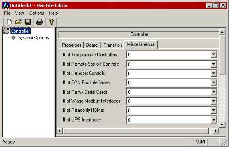
Miscellaneous tab |
Use the drop-down lists in the Miscellaneous tab to add |
|
various external devices to the .hwi file. The devices listed |
|
here are not automatically added by the Hardware Detect |
|
option. |
5 - Hwi text pane |
The selections you make in the tabbed pages of the |
|
controller definition pane are automatically reflected as text |
|
in this pane. |
|
The selections you make in the tabbed pages of the |
|
controller definition pane are automatically reflected as text |
|
in this pane. |
About Multiple .hwi Files
You can create multiple .hwi files that contain different hardware settings and save them in the same controller directory. This allows you to create custom .hwi settings for different tests. Custom settings may include different input filtering settings, DUC settings, and external hardware settings.
You can use the Project Manager application to select different .hwi files for use with a controller.
CAUTION:
For proper operation, the hardware resources specified in a configuration (.cfg) file must match those in the .hwi file.
Changing the hardware resources in an .hwi file can cause the system load operation to fail.
6 MTS Series 793 Utility Software
HWI-File-Editor Overview
When using multiple .hwi files with the same controller, make sure that your .hwi files all have identical hardware resources.
Saving Multiple .hwi Files in a Controller
Directory
You can create multiple .hwi files that contain different hardware settings and save them in the same controller directory. This allows you to create custom .hwi settings for different tests.
1. Shut down any test and quit all Series 793 applications.
CAUTION:
For proper operation, the hardware resources specified in a configuration (.cfg) file must match those in the .hwi file.
Changing the hardware resources in an .hwi file can cause the system load operation to fail.
When using multiple .hwi files with the same controller, make sure that your .hwi files all have identical hardware resources.
2.Use the HWI File Editor application to create a new .hwi file with a new name and custom settings.
3.From the File menu, click Save As.
4.In the Save As window, select the new controller directory and click Save. The following window appears:
If you click Yes, the file is saved in the controller directory and the controller.793settings file is modified to point to the new .hwi file. The next time you start a controller application, it will use the new .hwi file.
MTS Series 793 Utility Software 7

HWI-File-Editor Overview
If you click No, the file is saved in the controller directory but the controller.793settings file is not modified.
Note:
You can now use the Project Manager application to switch between the multiple .hwi files that you saved in the controller directory.
Selecting .hwi Files in a Controller Directory
You can use the Project Manager application to select different .hwi files for use with a controller.
1. Shut down any test and quit all Series 793 applications.
CAUTION:
For proper operation, the hardware resources specified in a configuration (.cfg) file must match those in the .hwi file.
Changing the hardware resources in an .hwi file can cause the system load operation to fail.
When using multiple .hwi files with the same controller, make sure that your .hwi files all have identical hardware resources.
2.Start the Project Manager application.
3.From the Tools menu, click Controller Settings.
4.In the controller list, click the Hwi file.
5.In the Hwi File text box, type the name of the .hwi file that you want to use.
6.Click OK.
The controller.793settings file is modified to point to the .hwi file. The next time you start a controller application, it will use the .hwi file that you defined above.
8 MTS Series 793 Utility Software

Create and Edit an HWI File
Topics: |
|
• Create a New File................................................................................................................. |
10 |
• Hardware Resources............................................................................................................ |
10 |
• Configure Hardware Resource Settings............................................................................... |
12 |
• About Actuator Movement When the Servovalve is Clamped............................................... |
15 |
• Where to Find Valve Balance Procedures............................................................................ |
16 |
MTS Series 793 Utility Software 9

Create and Edit an HWI File
Create a New File
Create New hwi File for Single Box System
Only qualified personnel should create or edit .hwi files.
WARNING:
An incorrect .hwi file can result in improper system response and unexpected actuator movements.
Unexpected actuator movements may result in personal injury or damage to equipment.
Before operating your system, ensure the .hwi file you are using is valid for your situation.
1.From the File menu, click New.
2.Click the Controller icon in the tree view pane.
3.Click the Properties tab, and select a Controller Type from the drop-down list.
Hardware Resources
Hardware Resources Listed in .hwi File
The hardware resources listed in the .hwi file must exactly match the physical location and address settings for each board used in the system. There are two methods to add hardware resources to an .hwi file:
•Use the Detect Hardware feature to detect VME and transition bus hardware and add those resources to the current file opened in the Hwi File Editor application.
•Use the Hwi File Editor application to manually add hardware resources.
About Detect Hardware Feature
The Detect Hardware feature automatically detects VME and transition bus hardware and adds those resources to the current file opened in the Hwi File Editor application. This is the preferred method when you create a new .hwi file. The Detect Hardware feature will also remove hardware resources from an existing .hwi file if that hardware was physically removed from the chassis.
10 MTS Series 793 Utility Software
Create and Edit an HWI File
The Detect Hardware feature will not detect a Model 498.70 board, Model 497 chassis tab, or any hardware added through the Miscellaneous tab (such as temperature controllers, RSCs, and handsets). You must manually add those hardware resources for any system that uses those hardware types.
Use Detect Hardware Feature
1.Open either a new or existing .hwi file.
2.From the Options menu, click Detect Hardware.
The detect hardware process adds and removes hardware resources based on what hardware was detected.
3.All detected hardware appears in the hardware resource tree. (Slot numbers for each board appear in brackets.)
4.Manually add any hardware that appears in the Miscellaneous tab (such as, temperature controllers, RSCs, and handsets).
About .hwi Miscellaneous Hardware
Any hardware listed in the Miscellaneous tab must be added manually using the HWI Editor application.
The Detect Hardware feature will not detect or add any hardware listed in the Miscellaneous tab.
Manually Add VME Board to .hwi File
The Hwi File Editor application includes a tree structure and drop-down lists that allow you to manually add hardware resources.
1. Select the Controller icon in the tree view pane.
MTS Series 793 Utility Software 11

Create and Edit an HWI File
2. Click the Board tab, and select the VME board for each board slot used in the system.
Manually Add Mezzanine Card to .hwi File
The Hwi File Editor application includes a tree structure and drop-down lists that allow you to manually add hardware resources.
1.Select the Model 49x.40 I/O Carrier or Model 493.50 ADDAII board in the tree view pane.
Empty I/O Carrier and ADDA II boards are not supported. At least one mezzanine card must be specified.
2.Click the Mezzanines tab, and select the mezzanine card type for each mezzanine location. You can also right-click a resource and select a mezzanine card from the pop-up menu.
Manually Add Transition Board to .hwi File
The Hwi File Editor application includes a tree structure and drop-down lists that allow you to manually add hardware resources.
1.Select Controller in the tree view pane.
2.Click the Transition tab, and select the appropriate DIO, HPU or HSM transition boards for each transition slot.
Configure Hardware Resource Settings
Valve Driver Settings
Each valve driver has settings that may include valve mode (single/dual), current range, and clamp mode settings.
In addition, any combination card (Model 494.16 VD/DUC) must be configured as either a two-stage or three-stage valve driver.
Digital Universal Conditioner (DUC) Settings
Each DUC card requires a number of hardware settings that you must configure before attempting to use the system.
DUC Mode Settings (AC/DC)
Each DUC card must be configured as either an AC or a DC conditioner (Default=DC).
12 MTS Series 793 Utility Software

Create and Edit an HWI File
Bridge Type Settings
Model 494.xx DUCs include settings that define the bridge type (full, half, quarter).
Shunt Settings
Model 494.xx DUCs include settings that define where the shunt calibration resistor is applied.
Analog Input Filter Settings
Mezzanine cards that include analog inputs (DUCs, A/D Converter, Encoder, and conditioners) includes filter settings that you may want to change for custom applications.
Encoder Type Settings
Each Encoder card requires a number of hardware settings that you must configure before attempting to use the system.
Hydraulic Interface Settings
Various HSM, HPU, and system boards have hydraulic interface settings that you must define before attempting to run the system. These settings vary with each board and may include first on/last off, proportional-on/off solenoid operation, and proportional rate settings.
The drawing shows examples for the following hydraulic interface settings:
Number callout in graphic - Item |
Description |
|
1 |
- HPU with HSM |
Hydraulic Power Unit (HPU) with Hydraulic Service |
|
|
Manifold (HSM) |
2 |
- HPU Only |
Hydraulic Power Unit (HPU) only |
MTS Series 793 Utility Software 13

Create and Edit an HWI File |
|
Number callout in graphic - Item |
Description |
3 - Controller |
Controller chassis |
4 - HPU with HSM |
This setting is available for the HPU transition and system |
|
boards (494.41, 494.42, 494.44, 493.42). |
|
TRUE–indicates the system’s HPU supplies one or more |
|
HSMs. |
|
FALSE–used for HPU only systems (makes HPU |
|
selection available in Station Builder). |
5 - Connect to HPU |
This setting is available for various HSM transition |
|
boards. |
|
TRUE–indicates that the HPU must be started (either |
|
manually or as “first on”) before you can activate an HSM. |
|
FALSE–indicates the HSM can be activated without an |
|
HPU activation. |
Optional Hardware Resource Name Changes
If you change the name of a hardware resource, you may invalidate existing configuration files. This is because an existing configuration file depends on the names of the resources in the current
.hwi file matching the names of the resources with which the configuration was created. (These are the names displayed in the Hardware Resources lists in the Station Builder application.)
If the names do not match, the configuration will not load into Series 793.00 System Software applications.
Resource naming convention
Hwi files typically use the following resource naming convention for valve driver and conditioner resources:
Convention: Resource model; Slot number; Connector number.
Example 1: 493.14 2SVD S5-J5.
Explanation: An MTS Model 493.14 2-Stage Servovalve Driver Board located in Slot 5 of the chassis whose output is available from Connector J5.
Example 2: 493.21B DUC S3-J4.
Explanation: An MTS Model 493.21B Digital Universal Conditioner Board located in Slot 3 of the chassis whose input is available at Connector J4.
VME Board Address Settings
If you use the Hardware Detect feature to add hardware resources, the board addresses are correct and no further action is required.
14 MTS Series 793 Utility Software

Create and Edit an HWI File
If you manually added the hardware resources to the .hwi file, you must make sure that the address setting in the .hwi file matches the physical address switch settings on the 493.40 I/O Carrier board, 494.40 I/O Carrier Board, and the ADDA II board.
About Actuator Movement When the Servovalve is Clamped
If an unbalanced servovalve (two-stage or three-stage) is clamped by Series 793 software, it may act unpredictably. In addition, if a three-stage servovalve is clamped when its third stage is not properly tuned, it may act unpredictably.
Servovalve balance
To balance a servovalve, you must first perform a mechanical adjustment on the servovalve to achieve gross mechanical balance. You can then use the Series 793 software Valve Balance to perform an electrical adjustment to fine-tune the mechanical adjustment.
Mechanical balance
The mechanical adjustment must be performed before the electrical adjustment, and is typically performed at the following times:
•At system installation
•When a new servovalve is installed in an existing system
•If the servovalve cannot be electrically balanced
•At regular service intervals
Electrical balance
The electrical adjustment is performed with the Valve Balance control, which adjusts the electrical input to the servovalve to compensate for minor mechanical imbalances. When the valve-balance adjustment is complete, there should be no (or minimal) hydraulic fluid flow when the servovalve output signal is at null.
Note:
The electrical adjustment is typically performed much more frequently than the mechanical adjustment.
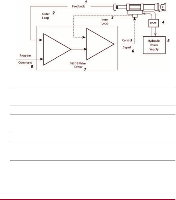
Inner-loop tuning
In addition to mechanical and electrical valve-balance adjustments, three-stage servovalves also have inner-loop tuning controls that may affect clamping behavior. The inner loop is similar to a displacement control mode for the outer-loop.
The inner control loop resides inside the test system’s primary, or outer control loop. So in addition to the pilot spool, three-stage servovalves include a third stage (or main) spool, that is driven by the pilot spool.
MTS Series 793 Utility Software 15
Create and Edit an HWI File
The inner loop (like the outer loop), has gain and rate controls that can be adjusted to optimize performance. The inner-loop is tuned at system installation, and requires periodic fine tuning when the outer-loop becomes sluggish.
Number callout in graphic |
Item |
1 |
Feedback |
|
|
2 |
Outer Loop |
3 |
Inner Loop |
4 |
Hydraulic Service Manifold (HSM) |
5 |
Hydraulic Power Supply |
6 |
Control Signal |
7 |
493.15 Valve Driver |
8 |
Program Command |
The innerloop (proportional) gain and rate (derivative) adjustments are the same types of adjustments as the proportional and derivative gain adjustments of the outer-loop tuning controls.
Where to Find Valve Balance Procedures
Mechanical valve-balance procedures
For two-stage servovalves, the mechanical valve balance procedure is included in the Series 252 Servovalve Product Manual (PN 011-182-906), which is typically included in the system documentation set.
16 MTS Series 793 Utility Software
Loading...