


 Loading...
be certain.
MTS Models FlexTest® IIm/GT/SE Controller Hardware
Service Information for Controllers Using Series 793 Software:
-Hardware Descriptions
-Specifications
-Installation
-Cabling
100-147-133 G
Copyright information Trademark information
© 2006, 2007, 2008, 2009 MTS Systems Corporation. All rights reserved.
MTS, FlexTest, Temposonics, and TestWare are registered trademarks of MTS Systems Corporation; MPT, Station Builder, and Station Manager are trademarks of MTS Systems Corporation within the United States. These trademarks may be protected in other countries.
Microsoft and Windows are registered trademarks of Microsoft Corporation. All other trademarks or service marks are property of their respective owners
Publication information |
MANUAL PART NUMBER |
PUBLICATION DATE |
MTS 793 SOFTWARE RELEASE |
|
|
|
|
|
100-147-133 A |
June 2006 |
Version 4.0A or later |
|
|
|
|
|
100-147-133 B |
October 2006 |
Version 4.0B or later |
|
|
|
|
|
100-147-133 C |
December 2006 |
Version 4.0B or later |
|
|
|
|
|
100-147-133 D |
November 2007 |
Version 5.0B or later |
|
|
|
|
|
100-147-133 E |
January 2008 |
Version 5.0B or later |
|
|
|
|
|
100-147-133 F |
September 2008 |
Version 5.1A or later |
|
|
|
|
|
100-147-133 G |
August 2009 |
Version 5.2A or later |
|
|
|
|
2 |
Models FlexTest® IIm/GT/SE Controller Hardware |

Contents
Technical Support |
9 |
|
|
|
|
|
|
||||
How to Get Technical Support |
9 |
||||
Before You Contact MTS 10 |
|
||||
If You Contact MTS by Phone |
11 |
||||
Problem Submittal Form in MTS Manuals 12 |
|||||
Preface 15 |
|
|
|
|
|
|
|
|
|
||
Before You Begin |
15 |
|
|
||
Conventions 16 |
|
|
|
|
|
Documentation Conventions 16 |
|||||
Chapter 1 |
Introduction |
19 |
|||
|
|
|
|
|
|
FlexTest GT Controllers |
20 |
|
|
|
|
Model 493.10 Chassis |
20 |
|
|||
Hydraulic Control |
22 |
|
|
||
Interlocks |
22 |
|
|
|
|
Specifications |
23 |
|
|
|
|
FlexTest SE Controllers |
24 |
|
|
|
|
Model 493.02 Chassis |
26 |
|
|||
Hydraulic Control |
26 |
|
|
||
Interlocks |
26 |
|
|
|
|
Specifications |
27 |
|
|
|
|
FlexTest IIm Controllers |
28 |
|
|
||
Model 497.01 Analog Chassis |
30 |
||||
Model 497.05 Hydraulic Control Panel 31 |
|||||
Model 498.22 Chassis with Test Processor (FTIIm) 32 |
|||||
Specifications |
33 |
|
|
|
|
Models FlexTest® IIm/GT/SE Controller Hardware |
Contents |
3 |

Chapter 2 |
Installation 37 |
|
|
Installing the Model 493.10 Chassis (FTGT) |
37 |
|
|
|
|
||||
Connecting Electrical Power 38 |
|
|
|
|
|
||||
Installing the Plug-in Modules |
42 |
|
|
|
|
|
|||
VMEbus Modules |
43 |
|
|
|
|
|
|
|
|
Installing the Transition Panels |
47 |
|
|
|
|
|
|||
Installing the 493.02 Chassis (FlexTest SE) |
49 |
|
|
|
|
||||
Installing the Plug-in Modules |
|
49 |
|
|
|
|
|
|
|
VMEbus Modules |
50 |
|
|
|
|
|
|
|
|
Chassis Installation Options |
51 |
|
|
|
|
|
|
||
Connecting Electrical Power |
53 |
|
|
|
|
|
|
||
Installing the Handle Kit |
58 |
|
|
|
|
|
|
|
|
Installing 497/498 Electronics (FTIIm) |
61 |
|
|
|
|
|
|||
Connecting the Console and Chassis Power |
61 |
|
|
|
|||||
How To Connect the Chassis Power Cables |
61 |
|
|
||||||
How To Cable the Analog Chassis to the Hydraulic Control Panel |
62 |
||||||||
Grounding the Console and Chassis |
62 |
|
|
|
|
|
|||
Model 497.01 Analog Chassis |
|
63 |
|
|
|
|
|
|
|
About Analog Chassis Slots |
63 |
|
|
|
|
|
|||
Analog Chassis Plug-in Modules 64 |
|
|
|
|
|||||
How to Install or Remove a Plug-in Module |
65 |
|
|
||||||
Analog Chassis Transition Modules |
66 |
|
|
|
|
|
|||
How To Install a Transition Module |
66 |
|
|
|
|
||||
Transition Module Connectors |
67 |
|
|
|
|
|
|||
Adding an Analog Chassis to Your Console |
69 |
|
|
|
|||||
Model 497.05 Hydraulic Control Panel |
71 |
|
|
|
|
||||
Test Processor Plug-in Modules |
72 |
|
|
|
|
|
|
||
Test Processor Transition Modules |
74 |
|
|
|
|
|
|||
UPS Systems 76 |
|
|
|
|
|
|
|
|
|
UPS Systems for FlexTest 60, 100, 200, and GT Controllers |
76 |
|
|||||||
UPS Systems for FlexTest 40 and FlexTest SE Servocontrollers |
77 |
||||||||
Specifications–UPS Systems Used with MTS Controllers |
78 |
|
|||||||
UPS Connections for the Model 493.73 HPU Board (FT60, FT100, FT200, FTGT) 79 UPS Connections for the Model 493.42 System board (FlexTest SE ) 80
4 |
Contents |
Models FlexTest® IIm/GT/SE Controller Hardware |

Chapter 3 |
FlexTest GT Controller Connections 81 |
|
|
|
|
CE EMC Compliant Cabling 83 |
|
|
Typical Cabling |
84 |
|
Cable Part Numbers 85 |
|
|
Model 493.40 I/O Carrier Connections |
87 |
|
Sensor Connections 88 |
|
|
Model 493.21B (DUC B) Jumpers |
92 |
|
Digital Universal Conditioner (DUC BC) Switches 94
Full-Range Digital Universal Conditioner (FRDUC) Jumpers 97
Sensor Cables 100 |
|
|
|
|
|
|
|
Sensor Cable Specifications |
100 |
|
|||||
Sensor Cable Part Numbers |
101 |
|
|||||
Shunt Calibration/Bridge Completion Resistor Installation 103 |
|||||||
I/O Carrier Module |
103 |
|
|
|
|||
Transducer Identification Modules |
106 |
||||||
Valve Connections |
|
108 |
|
|
|
|
|
Multiple Universal Driver Connections |
112 |
||||||
Analog I/O Connections |
114 |
|
|
||||
Accelerometer Connections |
119 |
|
|
||||
Encoder Connections |
121 |
|
|
|
|||
Remote Setpoint Adjust Connections |
123 |
||||||
ADDA II Connections |
124 |
|
|
|
|||
Emergency Stop Connections |
129 |
|
|||||
J25 Hydraulic Power Unit Connection |
131 |
||||||
Station Connections |
|
134 |
|
|
|
|
|
J28 Hydraulic Service Manifold Connector 134 |
|||||||
J29 Load Unit |
|
136 |
|
|
|
|
|
J43 Interlock |
137 |
|
|
|
|
||
J44 Run/Stop |
138 |
|
|
|
|
||
J49 Auxiliary Power |
140 |
|
|
||||
Digital I/O Connections |
141 |
|
|
|
|||
Workstation Connection |
145 |
|
|
||||
Remote Station Controller Connection |
147 |
||||||
Service Connections |
|
149 |
|
|
|
||
Models FlexTest® IIm/GT/SE Controller Hardware |
Contents |
5 |

Cabling and Programming Series 407 Controllers 151 |
|
|||||
How to Provide Program to a Series 407 Controller |
151 |
|||||
Connecting Interlock Signals to 407 Controllers 156 |
||||||
Sending and Receiving Signals to a Model 407 Controller 162 |
||||||
Connecting Interlock Signals to 458 Controllers |
164 |
|
||||
Eurotherm Temperature Controller Connection |
165 |
|
||||
Miscellaneous Conditioner Output Connections |
167 |
|
||||
Cabling for External Command Inputs 168 |
|
|
||||
How to Enable and Run External Command Inputs |
168 |
|||||
Cabling and Using External Readout Devices |
169 |
|
||||
How to Send Signals to External Readout Devices |
171 |
|||||
Multi-Box I/O Module |
172 |
|
|
|
||
J8 Interlock IN |
172 |
|
|
|
||
J9 Interlock OUT |
173 |
|
|
|
||
J51 Box In |
174 |
|
|
|
|
|
J52 Box Out |
|
175 |
|
|
|
|
Chapter 4 |
FlexTest IIm Controller Connections 177 |
|||||
|
|
|
|
|||
Workstation Connection |
178 |
|
|
|||
Sensor and Valve Connections 179 |
|
|
||||
ADDA Module Connections |
183 |
|
|
|||
ADDA II Connections |
184 |
|
|
|
||
Hydraulic Connections |
189 |
|
|
|||
HPU Connections |
190 |
|
|
|
|
|
HSM Connections |
191 |
|
|
|||
Interlock Connections |
192 |
|
|
|||
Interlock Jumper Plugs |
193 |
|
|
|||
Serial Communications |
195 |
|
|
|||
Digital I/O Connections |
196 |
|
|
|||
Encoder/Temposonics Connections 200 |
|
|
||||
Remote Station Controller (RSC) Connections |
203 |
|
||||
Cabling and Programming External Controllers |
204 |
|
||||
How to Program an External Controller 204 |
|
|||||
Programming Eurotherm Temperature Controllers |
209 |
|||||
6 |
Contents |
Models FlexTest® IIm/GT/SE Controller Hardware |

Cabling for External Command Inputs |
210 |
|
|
|||||
How to Enable and Run External Command Inputs |
210 |
|||||||
Cabling and Using External Readout Devices |
213 |
|
||||||
How to Send Signals to External Readout Devices |
213 |
|||||||
Cable Part Numbers |
216 |
|
|
|
|
|
||
Chapter 5 |
|
FlexTest SE Controller Connections 217 |
||||||
|
|
|
|
|
||||
Stand-alone Cabling Overview |
218 |
|
|
|
||||
Automated Cabling Overview |
219 |
|
|
|
||||
Multiple Controller Connections 220 |
|
|
|
|||||
Cable Part Numbers |
223 |
|
|
|
|
|
||
Model 493.40 I/O Carrier Connections |
225 |
|
|
|||||
Sensor Connections |
226 |
|
|
|
|
|||
Valve Connections 226 |
|
|
|
|
||||
Analog I/O Connections |
226 |
|
|
|
||||
Encoder Connections |
228 |
|
|
|
||||
Workstation Connection |
229 |
|
|
|
||||
Service Connection |
229 |
|
|
|
|
|||
Model 493.42 System I/O Connections |
230 |
|
|
|||||
J25 |
Hydraulic Power Unit Connection 230 |
|
||||||
J28 |
Hydraulic Service Manifold Connector |
231 |
|
|||||
J29 |
Emergency Stop Connections |
232 |
|
|
||||
J43 |
Interlock |
233 |
|
|
|
|
|
|
J49 |
Auxiliary Power |
234 |
|
|
|
|||
CJ51 Box In |
234 |
|
|
|
|
|
||
J52 |
Box Out |
235 |
|
|
|
|
|
|
J54 |
Digital Inputs |
236 |
|
|
|
|
||
J55 |
Digital Outputs |
237 |
|
|
|
|
||
Eurotherm Temperature Controller Connection |
239 |
|
||||||
Models FlexTest® IIm/GT/SE Controller Hardware |
Contents |
7 |

Appendix A |
Hydraulic Configurations 243 |
|||
|
|
|||
Model 493.02 Chassis Multiple Controller Interconnections |
246 |
|||
Independent HSM (no HPU) 246 |
|
|
||
Independent HSM (shared HPU) 247 |
|
|
||
Shared HSM (with HPU) |
247 |
|
|
|
Shared HSM (no HPU) |
248 |
|
|
|
Independent HSM with HPU (First On-Last Off) |
249 |
|
||
Appendix B |
Model 493.07 Converter Box |
251 |
||
|
|
|
|
|
Appendix C |
Chassis Maintenance |
253 |
|
|
|
|
|||
Appendix D |
Optional Station Configurations 255 |
|||
|
|
|
|
|
6-Station Configuration 255
8-Station Configuration 256
Index 257
8 |
Contents |
Models FlexTest® IIm/GT/SE Controller Hardware |

How to Get Technical Support
Technical Support
How to Get Technical Support
Start with your manuals
Technical support methods
www.mts.com
Telephone
Fax
Outside the U.S.
The manuals supplied by MTS provide most of the information you need to use and maintain your equipment. If your equipment includes software, look for online help and README files that contain additional product information.
If you cannot find answers to your technical questions from these sources, you can use the Internet, e-mail, telephone, or fax to contact MTS for assistance.
MTS provides a full range of support services after your system is installed. If you have any questions about a system or product, contact Technical Support in one of the following ways.
The web site provides access to our technical support staff by means of an onlineform:
www.mts.com > Contact MTS > Service & Technical Support button
tech.support@mts.com
MTS Call Center 800-328-2255
Weekdays 7:00 A.M. to 5:00 P.M., Central Time
952-937-4515
Please include “Technical Support” in the subject line.
For technical support outside the United States, contact your local sales and service office. For a list of worldwide sales and service locations and contact information, use the Global MTS link at the MTS web site:
www.mts.com > Global MTS > (choose your region in the right-hand column) > (choose the location closest to you)
Models FlexTest® IIm/GT/SE Controller Hardware |
Technical Support |
9 |
Before You Contact MTS
Before You Contact MTS
Know your site number and system number
Know information from prior technical assistance
Identify the problem
MTS can help you more efficiently if you have the following information available when you contact us for support.
The site number contains your company number and identifies your equipment type (such as material testing or simulation). The number is typically written on a label on your equipment before the system leaves MTS. If you do not know your MTS site number, contact your sales engineer.
Example site number: 571167
When you have more than one MTS system, the system job number identifies your system. You can find your job number in your order paperwork.
Example system number: US1.42460
If you have contacted MTS about this problem before, we can recall your file based on the:
•MTS notification number
•Name of the person who helped you
Describe the problem and know the answers to the following questions:
•How long and how often has the problem occurred?
•Can you reproduce the problem?
•Were any hardware or software changes made to the system before the problem started?
•What are the equipment model numbers?
•What is the controller model (if applicable)?
•What is the system configuration?
10 |
Technical Support |
Models FlexTest® IIm/GT/SE Controller Hardware |
Know relevant computer information
If You Contact MTS by Phone
For a computer problem, have the following information available:
•Manufacturer’s name and model number
•Operating software type and service patch information
•Amount of system memory
•Amount of free space on the hard drive where the application resides
•Current status of hard-drive fragmentation
•Connection status to a corporate network
Know relevant software information
For software application problems, have the following information available:
•The software application’s name, version number, build number, and (if available) software patch number. This information can typically be found in the About selection in the Help menu.
•The names of other applications on your computer, such as:
–Anti-virus software
–Screen savers
–Keyboard enhancers
–Print spoolers
–Messaging applications
If You Contact MTS by Phone
A Call Center agent registers your call before connecting you with a technical support specialist. The agent asks you for your:
•Site number
•Name
•Company name
•Company address
•Phone number where you can be reached
If your issue has a notification number, please provide that number. A new issue will be assigned a unique notification number.
Models FlexTest® IIm/GT/SE Controller Hardware |
Technical Support |
11 |
Problem Submittal Form in MTS Manuals
Identify system type
Be prepared to troubleshoot
Write down relevant information
After you call
To enable the Call Center agent to connect you with the most qualified technical support specialist available, identify your system as one of the following types:
•Electromechanical material test system
•Hydromechanical material test system
•Vehicle test system
•Vehicle component test system
•Aero test system
Prepare to perform troubleshooting while on the phone:
•Call from a telephone close to the system so that you can implement suggestions made over the phone.
•Have the original operating and application software media available.
•If you are not familiar with all aspects of the equipment operation, have an experienced user nearby to assist you.
In case Technical Support must call you:
•Verify the notification number.
•Record the name of the person who helped you.
•Write down any specific instructions.
MTS logs and tracks all calls to ensure that you receive assistance for your problem or request. If you have questions about the status of your problem or have additional information to report, please contact Technical Support again and provide your original notification number.
Problem Submittal Form in MTS Manuals
Use the Problem Submittal Form to communicate problems with your software, hardware, manuals, or service that are not resolved to your satisfaction through the technical support process. The form includes check boxes that allow you to indicate the urgency of your problem and your expectation of an acceptable response time. We guarantee a timely response—your feedback is important to us.
12 |
Technical Support |
Models FlexTest® IIm/GT/SE Controller Hardware |
Problem Submittal Form in MTS Manuals
Access the Problem Submittal Form:
•In the back of many MTS manuals (postage paid form to be mailed to MTS)
•www.mts.com > Contact Us > Problem Submittal Form button (electronic form to be e-mailed to MTS)
Models FlexTest® IIm/GT/SE Controller Hardware |
Technical Support |
13 |
Problem Submittal Form in MTS Manuals
14 |
Technical Support |
Models FlexTest® IIm/GT/SE Controller Hardware |

Before You Begin
Preface
Before You Begin
Safety first!
Other MTS manuals
Before you use your MTS product or system, read and understand the Safety manual and any other safety information provided with your system. Improper installation, operation, or maintenance can result in hazardous conditions that can cause severe personal injury or death, or damage to your equipment and specimen. Again, read and understand the safety information provided with your system before you continue. It is very important that you remain aware of hazards that apply to your system.
In addition to this manual, you may receive additional manuals in paper or electronic form.
You may also receive an MTS System Documentation CD. It contains an electronic copy of the manuals that pertain to your test system, such as:
•Hydraulic and mechanical component manuals
•Assembly drawings
•Parts lists
•Operation manual
•Preventive maintenance manual
Controller and application software manuals are typically included on the software CD distribution disc(s).
Models FlexTest® IIm/GT/SE Controller Hardware |
Preface |
15 |

Documentation Conventions
Conventions
Documentation Conventions
Hazard conventions
Notes
Special terms
The following paragraphs describe some of the conventions that are used in your MTS manuals.
Hazard notices may be embedded in this manual. These notices contain safety information that is specific to the activity to be performed. Hazard notices immediately precede the step or procedure that may lead to an associated hazard. Read all hazard notices carefully and follow all directions and recommendations. Three different levels of hazard notices may appear in your manuals. Following are examples of all three levels.
Note For general safety information, see the safety information provided with your system.

 DANGER
Danger notices indicate the presence of a hazard with a high level of risk which, if ignored, will result in death, severe personal injury, or substantial property damage.

 WARNING
Warning notices indicate the presence of a hazard with a medium level of risk which, if ignored, can result in death, severe personal injury, or substantial property damage.

 CAUTION
Caution notices indicate the presence of a hazard with a low level of risk which, if ignored, could cause moderate or minor personal injury or equipment damage, or could endanger test integrity.
Notes provide additional information about operating your system or highlight easily overlooked items. For example:
Note Resources that are put back on the hardware lists show up at the end of the list.
The first occurrence of special terms is shown in italics.
16 |
Preface |
Models FlexTest® IIm/GT/SE Controller Hardware |
Illustrations
Electronic manual conventions
Hypertext links
Documentation Conventions
Illustrations appear in this manual to clarify text. They are examples only and do not necessarily represent your actual system configuration, test application, or software.
This manual is available as an electronic document in the Portable Document File (PDF) format. It can be viewed on any computer that has Adobe Acrobat Reader installed.
The electronic document has many hypertext links displayed in a blue font. All blue words in the body text, along with all contents entries and index page numbers, are hypertext links. When you click a hypertext link, the application jumps to the corresponding topic.
Models FlexTest® IIm/GT/SE Controller Hardware |
Preface |
17 |
Documentation Conventions
18 |
Preface |
Models FlexTest® IIm/GT/SE Controller Hardware |

Chapter 1
Introduction
This manual contains installation, cabling, jumpering, and hardware interfacing information for MTS 793 Controllers.
This chapter describes the hardware components and specifications of FlexTest
GT, FlexTest SE, and FlexTest IIm Controllers.
Contents |
FlexTest GT Controllers |
20 |
|
|||
|
Model 493.10 Chassis |
20 |
||||
|
Hydraulic Control |
22 |
|
|||
|
Interlocks |
22 |
|
|
|
|
|
Specifications |
23 |
|
|
||
|
FlexTest SE Controllers |
24 |
|
|||
|
Model 493.02 |
Chassis |
26 |
|||
|
Hydraulic Control |
26 |
|
|||
|
Interlocks |
26 |
|
|
|
|
|
Specifications |
27 |
|
|
||
|
FlexTest IIm Controllers |
28 |
|
|||
|
Model 497.01 |
Analog Chassis 30 |
||||
|
Model 497.05 |
Hydraulic Control Panel 31 |
||||
|
Model 498.22 |
Chassis with Test Processor (FTIIm) 32 |
||||
|
Specifications |
33 |
|
|
||
Models FlexTest® IIm/GT/SE Controller Hardware |
Introduction |
19 |

Model 493.10 Chassis
FlexTest GT Controllers
MTS FlexTest GT Controllers are fully digital Proportional, Integral, Derivative, Feedforward (PIDF) servocontrollers which use an identical chassis configuration. They provide complete control of up to eight channels distributed among up to eight stations. Optional station configurations are available (see “Hydraulic Configurations” on page 243).
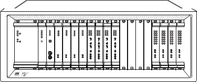
Model 493.10 Chassis
FlexTest GT Controllers use the Model 493.10 Chassis. The Model 493.10 Chassis is a multi-station, multi-channel VMEbus chassis which houses up to ten MTS VMEbus modules in its front panel and up to ten transition modules in its rear panel.
498.98-2 |
493.40 |
|
493.40 |
493.40 |
493.40 |
|
|
|
498.71B |
|
Power PC |
I/O Carrier |
I/O Carrier |
I/O Carrier |
I/O Carrier |
|
|
|
GRES III |
||
|
|
J3 Service |
J3 Service |
J3 Service |
J3 Service |
|
|
|
+12V |
|
|
|
|
|
|
|
|
|
|
|
CLOCK OUT |
ABT |
BFL |
Shunt Cal |
Shunt Cal |
Shunt Cal |
Shunt Cal |
|
|
|
EVENT OUT |
|
|
CPU |
|
|
|
|
|
|
|
|
|
RST |
|
|
|
|
|
|
|
|
|
EVENT IN |
|
PMC |
J4 I/O |
J4 I/O |
J4 I/O |
J4 I/O |
|
|
|
|
|
|
|
|
|
|
|
|
|
|
|
J3 IN |
|
|
|
|
|
|
|
|
|
|
J4 OUT |
|
|
J5 I/O |
J5 I/O |
J5 I/O |
J5 I/O |
|
|
|
|
|
|
|
|
|
|
|
|
|
|
|
J5 DEBUG |
|
|
|
|
|
|
|
|
|
|
J6 STATION |
|
|
J6 I/O |
J6 I/O |
J6 I/O |
J6 I/O |
|
|
|
|
|
|
|
|
|
|
|
|
|
|
|
J7 SERIAL |
|
|
J7 I/O |
J7 I/O |
J7 I/O |
J7 I/O |
|
|
|
|
|
m |
m m m m |
|
|
|
m |
|||||
1 |
2 |
3 |
|
4 |
5 |
6 |
7 |
8 |
9 |
10 |
|
MTS Sysrtems Corp |
|
|
|
|
|
|
|
|
|
lEden14000Prairie,TechnologyuMN 555344Dr. |
-2290 USA |
|
|
|
|
|
|
|||
|
Assy No: |
|
|
|
|
|
|
|
|
|
|
Model: |
S/N |
|
|
|
|
|
|
|
|
Front Panel
(with VMEbus Modules)
10 |
9 |
8 |
|
7 |
6 |
|
5 |
4 |
3 |
2 |
|
1 |
B |
A |
493.71 |
493.73 |
493.74 |
|
|
493.74 |
|
|
493.72 |
493.75 |
493.76 |
|
|
|
|
Serial |
HPU |
HSM |
|
|
HSM |
|
|
Digital I/O |
Analog In |
Analog Out |
|
|
|
|
Interface |
|
|
|
|
|
|
|
|
|
|
|
|
|
|
J50A |
|
|
|
|
|
|
|
+12V |
Ch 1 |
Ch 1 |
|
|
|
|
|
SERVICE |
J43A |
Intlk |
J43B |
J43A |
Intlk |
J43B |
|
|
|
|
|
||
|
|
|
|
|
|
|
|
|||||||
|
J23 |
|
|
|
|
|
|
|
|
|
|
|
|
|
|
E-STOP OUT |
|
|
|
|
|
|
|
Ch 2 |
Ch 2 |
|
|
|
|
|
|
|
|
|
|
|
|
J3 IN |
|
|
|
|
|
|
J50B |
|
|
|
|
|
|
|
|
Ch 3 |
Ch 3 |
|
|
|
|
|
|
J44A |
Run/Stop |
J44B |
J44A |
Run/Stop |
J44B |
|
|
|
|
|
||
|
J24 |
|
|
|
|
|
|
|
|
|
|
|
|
|
|
E-STOP IN |
|
|
|
|
|
|
|
Ch 4 |
Ch 4 |
|
|
|
|
J50C |
|
J49A |
Aux Pwr |
J49B |
J49A |
Aux Pwr |
J49B |
|
Ch 5 |
Ch 5 |
|
|
|
|
|
|
|
|
|
|
|
|
|
Ch 6 |
Ch 6 |
|
|
|
|
|
J25 HPS |
|
|
|
|
|
|
|
|
|
|
|
|
|
J50D |
|
J29A |
Load Unit |
J29B |
J29A |
Load Unit |
J29B |
|
|
|
|
|
|
|
|
|
|
|
|
|
|
|
J4 OUT |
|
|
|
|
|
|
J7 SERIAL |
J54 |
|
|
|
|
|
|
|
J11 |
J11 |
|
|
|
|
|
|
|
|
|
|
|
|
|
|
|
|
|||
|
SYS I/O |
J28A HSM |
|
J28A HSM |
|
|
(Ch 1-4) |
(Ch 1-4) |
|
|
|
|
||
|
|
|
|
|
|
|
|
|
J12 |
J12 |
|
|
|
|
|
|
J28B HSM |
|
J28B HSM |
|
|
(Ch 5-6) |
(Ch 5-6) |
|
|
|
|
||
m m m |
|
m |
|
m m m |
|
|
|
|||||||
|
|
|
l |
|
|
|
|
Power |
Over |
|
|
|
|
|
|
|
|
|
|
|
|
|
|
OK |
Temp |
J39 Power Monitor |
|
|
|
|
|
|
|
|
|
|
|
Power |
|
|
|
|
|
|
Rear Panel
(with Transition Modules)
20 |
Introduction |
Models FlexTest® IIm/GT/SE Controller Hardware |
Front panel
Rear panel
VMEbus modules
Transition bus
Cable conduit
Power supply
Model 493.10 Chassis
The Model 493.10 Chassis front panel has twelve slots; ten VMEbus slots and two slots (A and B) which are reserved.
The rear panel of the chassis has twelve transition bus slots. Two of these rear panel slots (slots A and B) can not be used with powered MTS transition modules. The chassis can be rack mounted or used in a floor standing configuration.
The chassis has ten VMEbus slots that support a variety of MTS VMEbus plugin modules.
•The chassis requires at least one processor module. The processor module provides the processing power to manage the other plug-in modules that make up the controller.
•The chassis can have up to eight I/O Carrier modules. Each I/O Carrier module supports up to four mezzanine cards.
•An optional Global Resource (GRES) module provides several connections to communicate with external devices such as a remote station control module, temperature controller, and other devices.
Transition modules are panels plugged into the transition bus located in the rear of the chassis. Each transition module allows external devices to interface with the chassis. Transition modules provide the following:
•Hydraulic control connections
•Station control connections
•Analog input and output connections
•Digital input and output connections
•Serial connections
The chassis has a conduit that allows cables to be routed from the front VMEbus modules to the rear transition modules and out of the chassis.
Two power supplies are used. One provides +5 V DC and ±15 V DC for the plugin modules; the other provides ±12 V DC for plug-in modules and +24 V DC for hydraulic power and the chassis fan. The power supplies have universal inputs and will adapt to any line voltage between 90 and 264 V AC.
The power supply is protected with an external circuit breaker in the On/Off switch that trips at a 10 amp overload. An internal fuse in the power supply is not user accessible or repairable.
Models FlexTest® IIm/GT/SE Controller Hardware |
Introduction |
21 |
Hydraulic Control
Cooling The chassis is cooled with a fan. An overtemperature sensor is part of the standard power supply assembly. If the internal chassis temperature exceeds 50ºC, this sensor will light an amber indicator located on the rear of the power supply module.
Hydraulic Control
Interlocks
System wide interlock
Station interlocks
Hydraulic control is handled with two transition modules:
•The Model 493.73 HPU Transition module has a connection to control a hydraulic power unit. It includes connections for an emergency stop button and digital I/O for system communications.
•Typically, up to four Model 493.74 HSM Transition Modules can be used to support up to eight HSM stations. Each HSM module includes connections to support two stations. Each station supports an HSM, a load unit, run/stop outputs, auxiliary outputs, and interlock controlled outputs.
Two types of interlocks are supported, the system wide interlock and station interlocks. The system wide interlock shuts down the hydraulic power unit and all stations, and the station interlock shuts down a single station leaving other stations running. The emergency stop function on the Model 493.74 HSM transition board contains two separate circuits, the system wide interlock (HPU) and the station interlock (HSM).
The emergency stop circuit consists of a loop that only runs through the rear panel transition boards of the chassis. Any board that generates an interlock by breaking this system wide loop causes the hydraulic power unit to be shut down. This will also cause all of the stations to shut down.
Note The emergency stop circuit meets the requirements of the Machinery Safety Directive (EN 60204-1, 1992, section 9.2.5.4). This means the emergency stop circuit is hard-wired with electromechanical components.
Each station represents all of the components associated with an interlock chain. All of the modules plugged into the chassis can be assigned to stations. If one of the stations generates an interlock, all of the components assigned to the station are shut down.
Standard configurations support up to four independent stations.
22 |
Introduction |
Models FlexTest® IIm/GT/SE Controller Hardware |

Specifications
Specifications
FlexTest GT Specifications
PARAMETER |
SPECIFICATION |
|
|
Environmental |
For indoor use only |
Temperature |
5ºC–40ºC (41ºF–104ºF) |
Relative humidity |
10%–85%, noncondensing |
Altitude |
For use at altitudes up to 2000 m |
|
(6500 ft) |
|
|
Power input |
power factor corrected universal input |
Input voltage* |
100–240 V AC |
Input frequency |
47–63 Hz |
Input surge |
<100 A |
Power |
<1000 W |
Insulation over |
Category II |
voltage |
|
Pollution degree |
2 |
|
|
Power supply #1 |
maximum draw is 400 W total |
+5 V DC |
40 A |
±15 V DC |
7.5 A |
|
|
Power supply #2 |
maximum draw is 400 W total |
±12 V DC |
4 A |
+24 V DC |
10 A |
|
|
Weight |
approximately 45 kg (100 lb) in stand |
|
alone configuration |
*The specification shown conforms to CE Low Voltage Directive requirements. The specification allows for 10% of the values stated. The actual voltage the 493.10 chassis can operate is
90–264 V AC.
Models FlexTest® IIm/GT/SE Controller Hardware |
Introduction |
23 |

Specifications
FlexTest SE Controllers
FlexTest SE Controller
FlexTest SE front panel controls
The MTS Model 493.02 FlexTest SE Controller is a fully digital Proportional, Integral, Derivative, Feedforward (PIDF) servocontroller. It provides complete control of one servohydraulic channel or station in an MTS test system.
The FlexTest SE may be operated in the standalone mode from its front panel controls, or in the automated mode with MTS Model 793.00 System Software running on a connected PC.
Operations are controlled through the controller’s front panel. An easy-to-read color display shows the status of the parameter currently being adjusted or monitored. A simple scroll-through menu provides quick access to any parameter or function. All parameters are entered through a keypad or adjusted by a single multi-turn dial. The current settings are saved in a flash disk and are recalled at start up.
In addition to providing the means to adjust and monitor the test parameters, the front panel also provides program control, system hydraulic pressure control, and an Emergency Stop button that shuts down the system hydraulics in an emergency situation. BNC monitor connectors are also provided to allow you to connect easily to external readout devices.
FlexTest SE |
A |
FG |
7 |
8 |
9 |
Rewind |
Run |
Hold |
Stop |
|
B |
Setup |
4 |
5 |
6 |
|
|
|
|
|
Recall |
Status |
|
|
Program |
||||
|
|
Scope |
1 |
2 |
3 |
|
Hydraulic |
|
|
|
|
|
Interlock |
reset |
|||||
|
|
|
|
|
|
||||
|
Enabled |
Meters |
+/- |
0 |
. |
|
Program |
||
|
|
Tuning |
|
Interlock |
|
|
|||
|
|
|
|
|
|
|
|
|
|
Emergency Stop |
|
|
Config |
enter |
Off |
Low |
High |
|
|
|
HPU |
|
|||
|
|
|
Limits |
cancel |
|
|
|
|
|
|
Log |
Off |
Low |
High |
|
|
|
|
|
|
HSM |
|
|
Monitor 1 Monitor 2 |
Navigate |
? |
Menu |
|
|
|
Power
TS-G436
FlexTest SE Front Panel
24 |
Introduction |
Models FlexTest® IIm/GT/SE Controller Hardware |
FlexTest SE stand-alone function generation
FlexTest SE automated configuration
Specifications
A function generator (with a built-in cycle counter) in the controller provides basic sine, square, triangle, and ramp command waveforms.
For tests requiring complex waveforms, the controller provides an external command input to receive externally generated commands.
The function generator waveform can be output to another MTS FlexTest SE Controller (or any external device) for synchronization.
In the automated configuration, the FlexTest SE Controller has added capabilities—it can acquire data, perform automated testing, apply complex control compensation techniques to the servoloop, and execute sophisticated test procedures that include complex triggering mechanisms.
The automated configuration includes the controller, a personal computer, and the Model 793.00 System Software bundle. It may also include optional MTS software for additional capability.
Models FlexTest® IIm/GT/SE Controller Hardware |
Introduction |
25 |

Model 493.02 Chassis
Model 493.02 Chassis
FlexTest SE Controllers use the Model 493.02 Chassis. The Model 493.02 Chassis is a single-station, single-channel VMEbus chassis which, in a typical configuration, houses three plug-in modules:
Model 493.02 Chassis
rear panel
•A Series 498 Processor
•A Model 493.40 I/O Carrier module
•A Model 493.42 System I/O module
Except for two front panel BNC connectors, all cabling is accessed through the controller’s rear panel. It is not necessary to remove the chassis cover to access jumpers or switches. The chassis can be rack mounted or used in a table-top configuration.
|
|
|
|
Power |
|
|
|
|
100–240 VAC |
|
|
|
|
–60 Hz, 12–6A |
|
RUN |
6TS |
BFL |
|
|
ABT |
|
RST |
|
TYPE E PC-MIP |
TYPE E PC-MIP |
|
DEBUG |
PCI MEZZANNE CARD |
|
|
|
|
TS-G435 |
FlexTest SE Rear Panel
Hydraulic Control
The controller provides complete control of the test system hydraulics. It can be used to control a hydraulic power unit and a hydraulic service manifold to apply low and high hydraulic pressure to the test system. In multiple controller configurations, the controller provides first-on/last-off control of the hydraulic power unit in addition to control of a local hydraulic service manifold.
Interlocks
The controller provides interlocks for adjustable upper/lower limit, underpeak, error detection for each sensor conditioner installed, and others. These interlocks can be daisy-chained for multiple controller configurations.
26 |
Introduction |
Models FlexTest® IIm/GT/SE Controller Hardware |

Specifications
Specifications
FlexTest SE Specifications
PARAMETER |
SPECIFICATION |
|
|
Environmental |
For indoor use only |
Temperature |
5ºC–40ºC (41ºF–104ºF) |
Relative humidity |
10%–85%, noncondensing |
Altitude |
For use at altitudes up to 2000 m |
|
(6500 ft) |
|
|
Power input |
power factor corrected universal input |
Input voltage* |
100–240 V AC |
Input frequency |
47–63 Hz |
Input surge |
<50 A |
Insulation over |
Category I |
voltage |
|
Pollution degree |
2 |
|
|
Weight |
approximately 8.6 kg (19 lb) |
*The specification shown conforms to CE Low Voltage Directive requirements. The specification allows for 10% of the values stated. The actual voltage the 493.02 chassis can operate is
90–264 V AC.
Models FlexTest® IIm/GT/SE Controller Hardware |
Introduction |
27 |

Specifications
FlexTest IIm Controllers
The MTS FlexTest IIm Controller is a fully digital Proportional, Integral,
Derivative, Feedforward (PIDF) servocontroller.
FlexTest IIm The FlexTest IIm configuration provides complete control of up to sixteen Controllers channels distributed among up to four stations in an MTS test system.
The FlexTest IIm Controller is available in five standard configurations. The FlexTest IIm Controller also supports optional components and custom configurations that can add features and capability to any standard configuration.
All configurations include the following components:
•Model 497.01 Analog Chassis
The analog chassis includes a complement of valve drivers and conditioners:
–Model 497.14 AC Conditioner module
–Model 497.22 Dual DC Conditioner module
–Model 497.26 Dual Valve Driver module
–Model 497.34 Multi-Station Interlock module
–Model 497.36 Communications module
•Model 497.05 Hydraulic Control Panel
The hydraulic control panel controls at least one Hydraulic Power Unit (HPU) or actuator manifold.
•Model 498.22 Test Processor Chassis
–Model 498.65 ADDA module
–Model 498.71B GRES III module
–Model 498.96-X Processor module
28 |
Introduction |
Models FlexTest® IIm/GT/SE Controller Hardware |
FT IIm standard configurations
Console
Customization
Specifications
•4, 6, 8, 12, or 16 channels of control
•16 inputs and 16 outputs of user DIO
•Per channel resources:
–One valve driver output
–One D/A output
–One A/D input
–One AC Conditioned input
–Two DC conditioned inputs
The FlexTest IIm Controller is available in a full-bay (vertical) console, a tabletop console, or a roll-around console.
Note The larger (full-bay) consoles can also accommodate rack-mount scopes, x-y recorders, and so forth.
A standard FlexTest IIm system can be customized for specific test requirements. In these cases, the standard hardware and software can be changed to accommodate a specific customer requirement.
Models FlexTest® IIm/GT/SE Controller Hardware |
Introduction |
29 |
Model 497.01 Analog Chassis
Model 497.01 Analog Chassis
The plug-in modules installed in the 497.01 Analog Chassis provide four main functions:
•Interlock control—An interlock control plug-in module provides programmable interlock signal mapping between the test processor and the modules installed in this analog chassis.
•Processor/Analog Chassis communications—A communications module provides data conversion between the test processor and the 497 analog plug-in modules.
•Transducer conditioning—AC and DC conditioners provide transducer excitation and output signal amplification for both low-level and high-level transducers.
•Valve drive signals—Valve drivers provide drive current for twoand threestage servovalves according to command inputs received for each channel.
|
497.34 |
497.35 |
497.14 |
497.14 |
497.14 |
497.14 |
497.22 |
497.22 |
497.22 |
497.22 |
497.26 |
497.26 |
497.26 |
497.26 |
||||||||
|
Station Cntrl |
RS422 Com |
AC Cond |
AC Cond |
AC Cond |
AC Cond |
DC Cond |
DC Cond |
DC Cond |
DC Cond |
Dual Valve |
Dual Valve |
Dual Valve |
Dual Valve |
||||||||
|
Station |
|
|
|
|
|
Ch |
Ch |
Ch |
Ch |
Ch |
Ch |
Ch |
Ch |
Ch |
Ch |
Ch |
Ch |
Ch |
Ch |
Ch |
Ch |
|
Interlocks |
|
|
|
|
|
1 |
2 |
1 |
2 |
1 |
2 |
1 |
2 |
||||||||
+15V |
1 |
Fault |
|
|
|
|
1 |
2 |
1 |
2 |
1 |
2 |
1 |
2 |
||||||||
U Lim |
U Lim |
U Lim |
U Lim |
|
U Lim |
|
U Lim |
|
U Lim |
|
U Lim |
|
|
|
|
|
|
|
|
|||
|
2 |
Xmit |
L Lim |
LLim |
L Lim |
L Lim |
|
L Lim |
|
L Lim |
|
L Lim |
|
L Lim |
|
|
|
|
|
|
|
|
-15V |
3 |
Ready |
Excit |
Excit |
Excit |
Excit |
|
Excit |
|
Excit |
|
Excit |
|
Excit |
|
|
|
|
|
|
|
|
4 |
Fail |
Fail |
Fail |
Fail |
|
Fail |
|
Fail |
|
Fail |
|
Fail |
|
|
|
|
|
|
|
|
||
|
|
|
|
|
|
|
|
|
|
|
|
|
|
|
|
|
|
|
|
|
|
|
-5V |
Power OK |
Reset |
|
|
|
|
|
|
|
|
|
|
|
|
|
|
|
|
|
|
|
|
|
|
|
|
|
|
|
|
R-Cal |
|
R-Cal |
|
R-Cal |
|
R-Cal |
|
|
|
|
|
|
|
|
|
|
|
|
|
|
|
|
1 |
|
1 |
|
1 |
|
1 |
|
|
|
|
|
|
|
|
|
|
|
|
|
|
|
|
R-Cal |
|
R-Cal |
|
R-Cal |
|
R-Cal |
|
|
|
|
|
|
|
|
|
|
|
|
|
|
|
|
2 |
|
2 |
|
2 |
|
2 |
|
Out 1 |
|
Out 1 |
|
Out 1 |
|
Out 1 |
|
|
x10 |
|
|
|
|
|
|
|
|
|
|
|
|
|
Gnd |
|
Gnd |
|
Gnd |
|
Gnd |
|
|
|
|
|
|
|
|
|
|
|
|
|
|
|
|
|
|
|
|
|
|
|
|
|
|
Out |
Out |
Out |
Out |
|
Out1 |
|
Out1 |
|
Out1 |
|
Out1 |
|
Out 2 |
|
Out 2 |
|
Out 2 |
|
Out 2 |
|
|
|
Gnd |
Gnd |
Gnd |
Gnd |
|
Out2 |
|
Out2 |
|
Out2 |
|
Out2 |
|
Gnd |
|
Gnd |
|
Gnd |
|
Gnd |
|
|
x1 |
|
Gnd |
|
Gnd |
|
Gnd |
|
Gnd |
|
|
|
|
||||||||
This chassis shows the maximum complement of modules for a standard FTIIm system. Customized systems can use all the module locations.
Note This chassis has rear panel transition modules and I/O connectors to support up to four independent test stations.
Analog Chassis (Front Panel)
30 |
Introduction |
Models FlexTest® IIm/GT/SE Controller Hardware |
Loading...