


647
Table of contents
 Loading...
Series 647 Hydraulic Wedge Grips Reference
Manual
Axial Grips Axial-Torsional Grips All-Temperature Grips
100-027-131 N be certain.

© 2013 MTS Systems Corporation. All rights reserved.
Original Instructions (English): 100-027-131 N
Trademark Information
MTS, be certain., Bionix, ElastomerExpress, FlatTrac, FlexTest, Just In Case, LevelPlus, MTS Criterion, MTS
EM Extend, MTS Insight, MTS Landmark, RPC, ServoSensor, SWIFT, Temposonics, TestWare, TestWorks are
registered trademarks of MTS Systems Corporation within the United States. Acumen, Advantage, Aero ST,
Aero-90, AeroPro, Criterion, CRPC, Echo, Flat-Trac, Landmark, MAST, MicroProfiler, MPT, MTS Acumen, MTS
Echo, MTS Fundamentals, MTS TestSuite, ReNew, SilentFlo, TempoGuard, TestLine, and Tytron are trademarks
of MTS Systems Corporation within the United States. These trademarks may be registered in other countries.
All other trademarks are property of their respective owners.
Proprietary Software
Software use and license is governed by the MTS End User License Agreement which defines all rights retained
by MTS and granted to the End User. All Software is proprietary, confidential, and owned by MTS Systems
Corporation and cannot be copied, reproduced, disassembled, decompiled, reverse engineered, or distributed
without express written consent of MTS.
Software Verification and Validation
MTS software is developed using established quality practices in accordance with the requirements detailed in
the ISO 9001 standards. Because MTS-authored software is delivered in binary format, it is not user accessible.
This software will not change over time. Many releases are written to be backwards compatible, creating another
form of verification. The status and validity of the MTS operating software is also checked during system verification
and routine calibration of MTS hardware. These controlled calibration processes compare the final test results
after statistical analysis against the predicted response of the calibration standards. With these established
methods, MTS assures its customers that MTS products meet exacting quality standards when initially installed
and will continue to perform as intended over time.
Manual Part Number—Publication Date—Release
100-027-131 M—April 2011
100-027-131 L—April 2010
100-027-131 K—April 2009
100-027-131 J—March 2008
100-027-131 H—Mat 2007
100-027-131 G—November 2006
100-027-131 F—July 2005
100-027-131 E—February 2003
100-027-131 D—October 2001
100-027-131 C—June 2011
100-027-131 B—December 2011
100-027-131 A—February 2000

Contents
Technical Support 7
Preface 11
Introduction 13
How to Get Technical Support.................................................................................................................7
Before You Contact MTS.........................................................................................................................7
If You Contact MTS by Phone.................................................................................................................9
Problem Submittal Form in MTS Manuals............................................................................................10
Before You Begin...................................................................................................................................11
Documentation Conventions..................................................................................................................11
Overview Reference...............................................................................................................................14
Series 647 Hydraulic Wedge Grips Component Identication..............................................................16
Series 647 Hydraulic Wedge Grips Functional Description...................................................................19
About Gripping Specimens....................................................................................................................20
About Wedges........................................................................................................................................20
About Spiral Washers.............................................................................................................................21
About Couplings....................................................................................................................................21
About All Temperature Grips.................................................................................................................21
About Environmental Chambers............................................................................................................22
Hydraulic Fluid Recommendations........................................................................................................23
Cooling Water Specications.................................................................................................................23
Series 647 Wedge Grip Temperature Ranges.........................................................................................23
Series 647 Hydraulic Wedge Grip Force and Torque Capacities...........................................................24
Safety 29
General Safety Practices: Grips and Fixtures.........................................................................................30
Read all manuals........................................................................................................................31
Avoid Pinch and Crush Points....................................................................................................31
Locate and read hazard placards/labels......................................................................................31
Know facility safe procedures....................................................................................................32
Know controls............................................................................................................................32
Know Specimen Properties........................................................................................................32
Have rst aid available...............................................................................................................32
Be aware of component movement with hydraulics off.............................................................32
Keep bystanders safely away.....................................................................................................32
Wear proper clothing..................................................................................................................32
Remove ammable uids..........................................................................................................32
Check bolt ratings and torques...................................................................................................33
Lift Equipment Safely................................................................................................................33
Series 647 Hydraulic Wedge Grips Reference Manual 3

Practice good housekeeping.......................................................................................................33
Do not exceed the Maximum Supply Pressure..........................................................................33
Do not disable safety devices.....................................................................................................33
Provide adequate lighting...........................................................................................................33
Provide means to access out-of-reach components....................................................................34
Wear appropriate personal protection.........................................................................................34
Handle chemicals safely ............................................................................................................34
Know system interlocks.............................................................................................................34
Know system limits....................................................................................................................34
Do not disturb sensors ...............................................................................................................34
Ensure secure cables...................................................................................................................34
Stay alert ....................................................................................................................................35
Contain small leaks ...................................................................................................................35
Stay clear of moving equipment/avoid crush points .................................................................35
Know the causes of unexpected actuator motions .....................................................................35
General Precautions for Environmental Components............................................................................35
Hazard Placard Placement......................................................................................................................36
Installation 37
Series 647 Hydraulic Grip Lift Points....................................................................................................38
Install Axial Grips..................................................................................................................................39
About the Installation of Axial Grips.........................................................................................39
Install Axial Grip........................................................................................................................42
Install Axial-Torsional Grips..................................................................................................................44
About the Installation of Axial-Torsional Grips.........................................................................44
Install Axial-Torsional Grip.......................................................................................................46
Install 647.250 Grips..............................................................................................................................50
Install the Grips in an Environmental Chamber.....................................................................................50
About Installation of the Grips in an Environmental Chamber .................................................50
Install Environmental Chambers with U-Plugs..........................................................................51
Install Environmental Chambers Without U-Plugs....................................................................55
Install Extension Rods............................................................................................................................66
About Extension Rod Installation..............................................................................................66
Install Extension Rods................................................................................................................67
Align the Wedge Openings.....................................................................................................................71
Preload the Spiral Washers.....................................................................................................................72
Grip Water Cooling Congurations.......................................................................................................74
Grip Water Cooling Assembly Conguration for Electromechanical Frames...........................74
Operation 77
Basic Operation......................................................................................................................................78
About Grip Controls...............................................................................................................................78
Determine Gripping Pressure.................................................................................................................79
4 Series 647 Hydraulic Wedge Grips Reference Manual

About Grip Pressure Determination...........................................................................................79
Determine Gripping Pressure -Axial for Round Specimens (and Axial/Torsional for Flat Specimens).81
Determine Gripping Pressure - Axial-Torsional for Round Specimens Only............................82
Change/Install Wedges...........................................................................................................................83
Change Model 647.02 - 647.100 Wedges..................................................................................83
Change Standard Wedges...........................................................................................................83
Change Wide Wedges.................................................................................................................84
Wedges and Inserts for Rebar and Wire Rope............................................................................85
Install Model 647.250 Wedges and Liners.................................................................................86
Install Model 647.250 Wedges.......................................................................................86
Install Model 647.250 Wedge Liners.............................................................................87
Install/Remove Test Specimen...................................................................................................88
Install a Specimen..........................................................................................................88
Remove a Specimen.......................................................................................................90
Maintenance 93
Hydraulic Hoses and Fittings.................................................................................................................94
Wedges...................................................................................................................................................94
Water Cooling Components...................................................................................................................94
Daily Inspections....................................................................................................................................94
Series 647 Hydraulic Wedge Grips Reference Manual 5


Technical Support
How to Get Technical Support
Start with your manuals
The manuals supplied by MTS provide most of the information you need to use and maintain your equipment.
If your equipment includes software, look for online help and README files that contain additional product
information.
Technical support methods
MTS provides a full range of support services after your system is installed. If you have any questions about
a system or product, contact Technical Support in one of the following ways.
Web site
Outside the U.S.
For technical support outside the United States, contact your local sales and service office. For a list of
worldwide sales and service locations and contact information, use the Global MTS link at the MTS web site:
www.mts.com > Global Presence > Choose a Region
www.mts.com > Contact Us (upper-right corner) > In the Subject field, choose
To escalate a problem; Problem Submittal Form
Worldwide: tech.support@mts.comE-mail
Europe: techsupport.europe@mts.com
Worldwide: 1 800 328 2255 - toll free in U.S.; +1 952 937 4000 - outside U.S.Telephone
Europe: +800 81002 222, International toll free in Europe
Before You Contact MTS
MTS can help you more efficiently if you have the following information available when you contact us for
support.
Know your site number and system number
The site number contains your company number and identifies your equipment type (such as material testing
or simulation). The number is typically written on a label on your equipment before the system leaves MTS.
If you do not know your MTS site number, contact your sales engineer.
Example site number: 571167
Series 647 Hydraulic Wedge Grips Reference Manual 7

When you have more than one MTS system, the system job number identifies your system. You can find
your job number in your order paperwork.
Example system number: US1.42460
Know information from prior technical assistance
If you have contacted MTS about this problem before, we can recall your file based on the:
• MTS notification number
• Name of the person who helped you
Identify the problem
Describe the problem and know the answers to the following questions:
• How long and how often has the problem occurred?
• Can you reproduce the problem?
• Were any hardware or software changes made to the system before the problem started?
• What are the equipment model numbers?
• What is the controller model (if applicable)?
• What is the system configuration?
Know relevant computer information
For a computer problem, have the following information available:
• Manufacturer’s name and model number
• Operating software type and service patch information
• Amount of system memory
• Amount of free space on the hard drive where the application resides
• Current status of hard-drive fragmentation
• Connection status to a corporate network
Know relevant software information
For software application problems, have the following information available:
• The software application’s name, version number, build number, and (if available) software patch number.
This information can typically be found in the About selection in the Help menu.
• The names of other applications on your computer, such as:
• Anti-virus software
• Screen savers
• Keyboard enhancers
• Print spoolers
• Messaging applications
8 Series 647 Hydraulic Wedge Grips Reference Manual

If You Contact MTS by Phone
A Call Center agent registers your call before connecting you with a technical support specialist. The agent
asks you for your:
• Site number
• Name
• Company name
• Company address
• Phone number where you can be reached
If your issue has a notification number, please provide that number. A new issue will be assigned a unique
notification number.
Identify system type
To enable the Call Center agent to connect you with the most qualified technical support specialist available,
identify your system as one of the following types:
• Electrodynamic material test system
• Electromechanical material test system
• Hydromechanical material test system
• Vehicle test system
• Vehicle component test system
• Aero test system
Be prepared to troubleshoot
Prepare to perform troubleshooting while on the phone:
• Call from a telephone close to the system so that you can implement suggestions made over the phone.
• Have the original operating and application software media available.
• If you are not familiar with all aspects of the equipment operation, have an experienced user nearby to
assist you.
Write down relevant information
In case Technical Support must call you:
• Verify the notification number.
• Record the name of the person who helped you.
• Write down any specific instructions.
Series 647 Hydraulic Wedge Grips Reference Manual 9

After you call
MTS logs and tracks all calls to ensure that you receive assistance for your problem or request. If you have
questions about the status of your problem or have additional information to report, please contact Technical
Support again and provide your original notification number.
Problem Submittal Form in MTS Manuals
Use the Problem Submittal Form to communicate problems with your software, hardware, manuals, or service
that are not resolved to your satisfaction through the technical support process. The form includes check
boxes that allow you to indicate the urgency of your problem and your expectation of an acceptable response
time. We guarantee a timely response—your feedback is important to us.
You can access the Problem Submittal Form at www.mts.com > Contact Us (upper-right corner) > In the
Subject field, choose To escalate a problem; Problem Submittal Form
10 Series 647 Hydraulic Wedge Grips Reference Manual

Preface
Before You Begin
Safety first!
Before you use your MTS product or system, read and understand the safety information provided with your
system. Improper installation, operation, or maintenance can result in hazardous conditions that can cause
severe personal injury or death, or damage to your equipment and specimen. Again, read and understand
the safety information provided with your system before you continue. It is very important that you remain
aware of hazards that apply to your system.
Other MTS manuals
In addition to this manual, you may receive additional manuals in paper or electronic form.
You may also receive an MTS System Documentation CD. It contains an electronic copy of the manuals that
pertain to your test system.
Controller and application software manuals are typically included on the software CD distribution disc(s).
Documentation Conventions
The following paragraphs describe some of the conventions that are used in your MTS manuals.
Hazard conventions
Hazard notices may be embedded in this manual. These notices contain safety information that is specific to
the activity to be performed. Hazard notices immediately precede the step or procedure that may lead to an
associated hazard. Read all hazard notices carefully and follow all directions and recommendations. Three
different levels of hazard notices may appear in your manuals. Following are examples of all three levels. (for
general safety information, see the safety information provided with your system.)
DANGER:
Danger notices indicate the presence of a hazard with a high level of risk which, if
ignored, will result in death, severe personal injury, or substantial property damage.
WARNING:
Warning notices indicate the presence of a hazard with a medium level of risk which,
if ignored, can result in death, severe personal injury, or substantial property damage.
CAUTION:
Series 647 Hydraulic Wedge Grips Reference Manual 11

Caution notices indicate the presence of a hazard with a low level of risk which, if
ignored, could cause moderate or minor personal injury or equipment damage, or
could endanger test integrity.
Other special text conventions
Important:
Important notices provide information about your system that is essential to its proper
function. While not safety-related, if the important information is ignored, test results may
not be reliable, or your system may not operate properly.
Note:
Notes provide additional information about operating your system or highlight easily
overlooked information.
Recommended:
Recommended notes provide a suggested way to accomplish a task based on what MTS
has found to be most effective.
Tip:
Tips provide helpful information or a hint about how to most efficiently accomplish a task.
Access:
Access provides the route you should follow to a referenced item in the software.
Example:
Examples show specific scenarios relating to your product and appear with a shaded
background.
Special terms
The first occurrence of special terms is shown in italics.
Illustrations
Illustrations appear in this manual to clarify text. They are examples only and do not necessarily represent
your actual system configuration, test application, or software.
Electronic manual conventions
This manual is available as an electronic document in the Portable Document File (PDF) format. It can be
viewed on any computer that has Adobe Acrobat Reader installed.
Hypertext links
The electronic document has many hypertext links displayed in a blue font. All blue words in the body text,
along with all contents entries and index page numbers, are hypertext links. When you click a hypertext link,
the application jumps to the corresponding topic.
12 Series 647 Hydraulic Wedge Grips Reference Manual

Introduction
Topics:
•
Overview Reference..............................................................................................................................14
•
Series 647 Hydraulic Wedge Grips Component Identification...............................................................16
•
Series 647 Hydraulic Wedge Grips Functional Description...................................................................19
•
About Gripping Specimens....................................................................................................................20
•
About Wedges.......................................................................................................................................20
•
About Spiral Washers............................................................................................................................21
•
About Couplings.....................................................................................................................................21
•
About All Temperature Grips..................................................................................................................21
•
About Environmental Chambers............................................................................................................22
•
Hydraulic Fluid Recommendations........................................................................................................23
•
Cooling Water Specifications.................................................................................................................23
•
Series 647 Wedge Grip Temperature Ranges.......................................................................................23
•
Series 647 Hydraulic Wedge Grip Force and Torque Capacities..........................................................24
Series 647 Hydraulic Wedge Grips Reference Manual 13
Introduction
Overview Reference
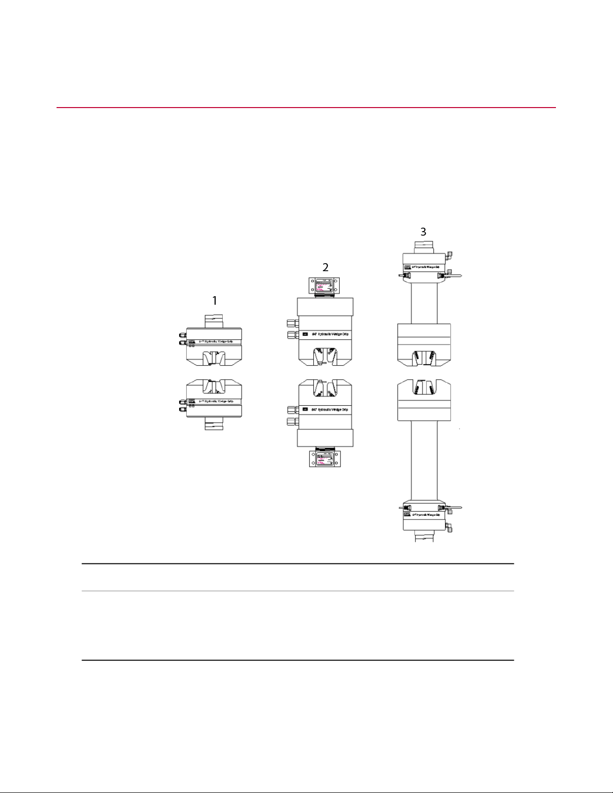
The MTS Series 647 Hydraulic Wedge Grips grasp and hold a specimen in place during testing, and provide
a constant, hydraulically actuated gripping force regardless of the applied test loads. The grips are specifically
designed for static or fatigue testing applications in MTS testing systems. A variety of wedges allow the grips
to be used to test a variety of materials. Optional equipment includes a cooling/warming kit and an external
hydraulic grip supply.
The size and shape of the Series 647 Hydraulic Wedge Grips vary among the models.
Grip TypeItem
Axial1
Axial-Torsional2
All Temperature3
What you need to know
MTS Systems Corporation assumes that you know how to use your controller. See the appropriate manual
for information about performing any controllerrelated step in this manual’s procedures. You are expected to
know how to perform the following procedures:
14 Series 647 Hydraulic Wedge Grips Reference Manual

Introduction
• Turn hydraulic pressure on and off.
• Select a control mode.
• Manually adjust the actuator position.
• Monitor a sensor signal.
Related products
See the following product information manuals for information about the related products.
• The hydraulic controls for the Series 647 Hydraulic Grips can be located on the front panel of the load unit
or on an external unit (controls and a hydraulic power unit for the grips).
• If hydraulic grip controls are located on the load unit, see your load unit product information manual.
• If hydraulic grip controls are added to your load unit, see the 685.53 Hydraulic Grip Kit Product
Information manual (MTS part number 015-029-701).
• If you have a dedicated hydraulic supply for the grips, see the Series 685 Hydraulic Grip Supply Product
Information manual (MTS part number 015-205-001).
• If you are using an environmental chamber, see the Series 651 Environmental Chambers Product
Information manual (MTS part number 015-205-001).
Series 647 Hydraulic Wedge Grips Reference Manual 15
Introduction
Series 647 Hydraulic Wedge Grips Component Identification
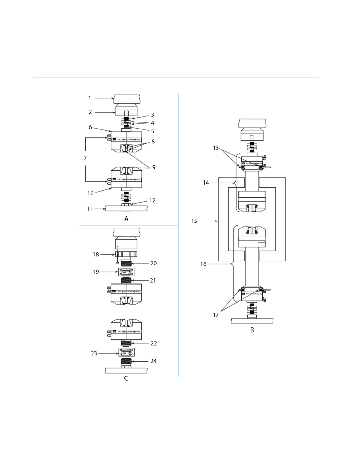
Series 647 Hydraulic Grip Components
16 Series 647 Hydraulic Wedge Grips Reference Manual

Introduction
DescriptionItemDescriptionItem
All Temperature GripsBAxial GripsA
Water Cooling Lines13Load Unit Crosshead1
Upper Grip Assembly14Force Transducer2
Environmental Chamber15Shim3
Lower Grip Assy16Spiral Washer Set4
Water Cooling Lines17Connector Stud5
Axial/Torsional GripsCUpper Grip6
Adapter Plate18Hydraulic Pressure and return Lines7
8
liners)
Load unit
• Crosshead and Base
Plate
Upper Coupling19Wedges (647.250 includes wedge
Left Hand Thread20Specimen Guide9
Right Hand Thread21Lower Grip10
Left Hand Thread22Load Unit Base11
Lower Coupling23Actuator Rod12
Right Hand Thread24
DescriptionItem
Provides the structure to mount the grips and other components in
the force train. It is also the reaction mass for the force train. The grips
are mounted to the force transducer and actuator rod in the load unit.
• Some load units have the actuator mounted in the base plate and
the force transducer mounted to the crosshead.
• Some load units have the force transducer mounted in the base
plate and the actuator mounted to the crosshead.
Force Transducer
Upper and lower grips
Hydraulic pressure and
return lines
Measures the axial forces applied to the specimen. An axial-torsional
version also measures the rotational forces applied to the specimen.
Clamps a specimen in place. The grips house the wedges and the
hydraulic components that operate the grips.
The grip assemblies of the all-temperature grips have the components
separated so those components most affected by extreme
temperatures are located outside the extreme environment.
Ports the hydraulic fluid to and from the grips. The hydraulic fluid
comes from a system hydraulic power unit (HPU) or a dedicated
Series 647 Hydraulic Wedge Grips Reference Manual 17

Introduction
DescriptionItem
hydraulic grip supply. Each grip has two hydraulic lines connected to
it; a hydraulic pressure port and a hydraulic return port.
Wedges
Specimen guide
Actuator rod
Water cooling lines
Environmental chamber
Contacts and holds the specimen in place. A variety of wedges are
available, for flat specimens, round specimens, hard specimens, and
soft specimens. Wedges are available as matched sets of four.
Each model has wedges that are designed for its use. The 647.250
grips have permanent wedges and use wedge liners to accommodate
various specimen shapes.
Helps align the specimen when it is installed. The specimen guide
can only be used with flat specimens.
Applies axial or axial and torsional forces to specimens. The actuator
is a hydraulically powered device that provides linear displacement
of (or forces into) a specimen. For axial-torsional systems, the actuator
applies both axial and torsional forces to the specimen.
The end of the actuator rod is threaded so that a grip can be mounted
to it. The actuator rod can be located in the base or the crosshead of
the load unit.
Provides the source of water for heating or cooling. The water is
circulated through the grips to keep them warm or cool when operating
in a cold or hot environmental chamber.
Allows a specimen to be tested at different temperatures (hot or cold).
Environmental chambers are insulated boxes that surround the
specimen and grips.
Axial attachment kit
• Shims
• Spiral washers
• Connector stud
Axial-torsional attachment
kit
Includes the required components to install the grips. The attachment
kit contains shim washers, spiral washers, and connector studs. Each
grip model/load unit model combination has a unique attachment kit.
Allows the upper and lower grips to be aligned. When the grips are
installed, the upper and lower grips might not be aligned. Shims can
be added so that the grips are aligned when they are tightened on
the connector stud. The shims are available in thicknesses that
correspond with 1/8 to 1/2 turns.
Ensures preloading without inducing offsets in the force train. They
provide a backlash-free union of threaded components. They preload
the connecting stud to a minimum axial load that is 110% of the test
maximum.
Mounts the grips to the other components in the force train. Connector
studs are threaded rods that connect the grips with an actuator rod
or force transducer.
Includes the required components to install the grips. The attachment
kit contains an adapter plate, an upper coupling, and a lower coupling.
Each grip model/load unit model combination has a unique attachment
kit.
18 Series 647 Hydraulic Wedge Grips Reference Manual
Introduction
DescriptionItem
• Adapter plate
• Upper and lower
couplings
Allows axial-torsional grips to be mounted to a force transducer. The
adapter provides the thread needed to use the couplings.
Clamps the grips to the to the actuator and force transducer (via an
adapter). The couplings have left and right handed threads that
preloads the grip connection and prevents offsets in the force train.
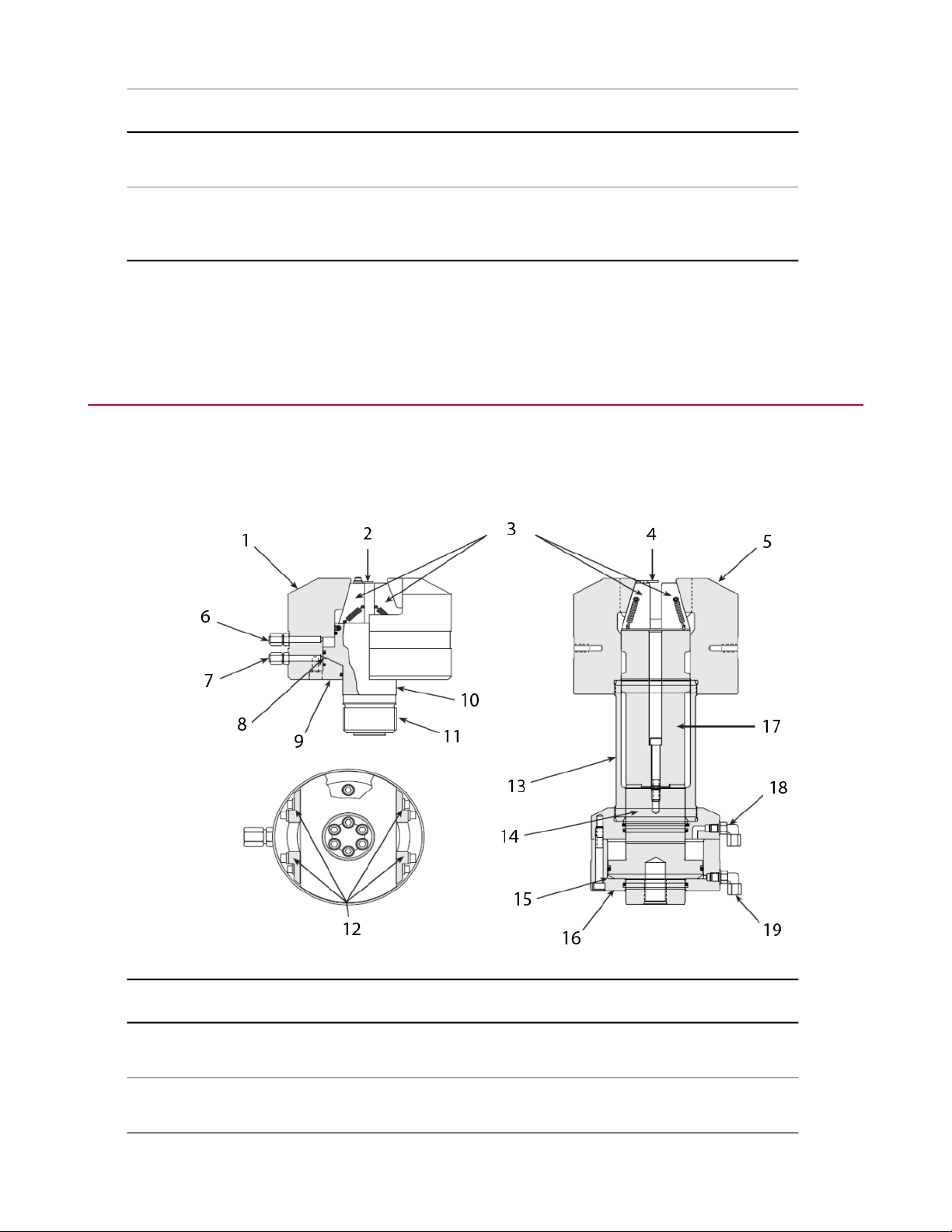
Series 647 Hydraulic Wedge Grips Functional Description
The Series 647 Hydraulic Wedge Grips are typically mounted in an MTS load unit to secure the specimen
under test. Hydraulic pressure to the grips is supplied by and adjusted at an external hydraulic grip supply.
The grips have a side loading design for quick and easy specimen installation.
DescriptionItemDescriptionItem
11Wedge Chamber1
2
only)
12Specimen Guide (flat specimens
Series 647 Hydraulic Wedge Grips Reference Manual 19
Anti-Rotate Adapter (Axial-Torsional
Only)
Anti-Rotate Blocks (Axial-Torsional
Only)

Introduction
DescriptionItemDescriptionItem
Cylinder13Wedges3
4
only)
Grip Piston10
Grip Piston14Specimen Guide (flat specimens
Preload Chamber15Wedge Chamber5
End Cap16Hydraulic Release6
Piston Extension17Hydraulic Pressure7
Hydraulic Release18Preload Chamber8
Hydraulic Pressure19End Cap9
About Gripping Specimens
The grips provide a constant, hydraulically actuated gripping force regardless of the applied test loads. The
specimen gripping force is adjustable to prevent specimen damage by the grips or specimen slippage during
the test. Each grip (upper and lower) is independently actuated. When actuated, the preload chamber locks
all moving grip parts in position, thus eliminating backlash when cycling between tension and compression.
The specimen can then be cycled from full tension through zero to full compression with no backlash.
Once a specimen is positioned between the grip wedges, hydraulic pressure is applied to the preload chamber.
This pressure pulls the wedge chamber toward the piston, forcing the wedges to clamp the specimen. The
pressure applied to the preload chamber can be adjusted to a level which clamps the specimen securely, but
does not damage the specimen by applying excessive gripping force.
About Wedges
Each grip model has its own selection of wedges. Not all wedge options are available for all grip models.
Three types of wedges are available for use with the grips: flat wedges, round wedges, and vee-notched
wedges.
• Flat wedges grip flat specimens. Both narrow and wide wedges are available.
• Round wedges can only grip a round specimen of a specific diameter.
• Vee-notched wedges can grip a range of round specimens.
Flat wedge surfaces can be finished with diamond serrations, with a Surfalloy coating, or a smooth finish.
• Diamond serrated surfaces can grip materials such as soft steels and plastics.
• Surfalloy surfaces can grip hard or brittle materials. Surfalloy incorporates a grit onto the wedge surface.
20 Series 647 Hydraulic Wedge Grips Reference Manual
• Smooth surfaces can grip specimens that cannot tolerate imperfections on the grip surface. This surface
also has a lower force rating.
Water-cooled wedges are available for applications where the specimen is heated. A water cooling kit includes
the parts to connect the wedges to a water source and regulate the water flow.
About Spiral Washers
The optional Model 601 Spiral Washers are commonly used when installing axial grips. They provide
fatigue-resistant connections between elements of the force train and minimize the effects of backlash.
The spiral washers are placed over the connector studs at each connection and adjusted to place a constant
preload on the stud. The spiral washers also minimize the possibility of backlash due to loose-fitting or worn
stud threads. When cyclic loads below the tensile force level of the preload are applied to the connections,
the load is distributed between the surfaces of the spiral washers and the stud in a ratio of the relative stiffness
of the parts. The spiral washers have a large surface area and therefore greater stiffness. They react to most
of the load and keep the stress in the stud below its fatigue runout level.
Introduction
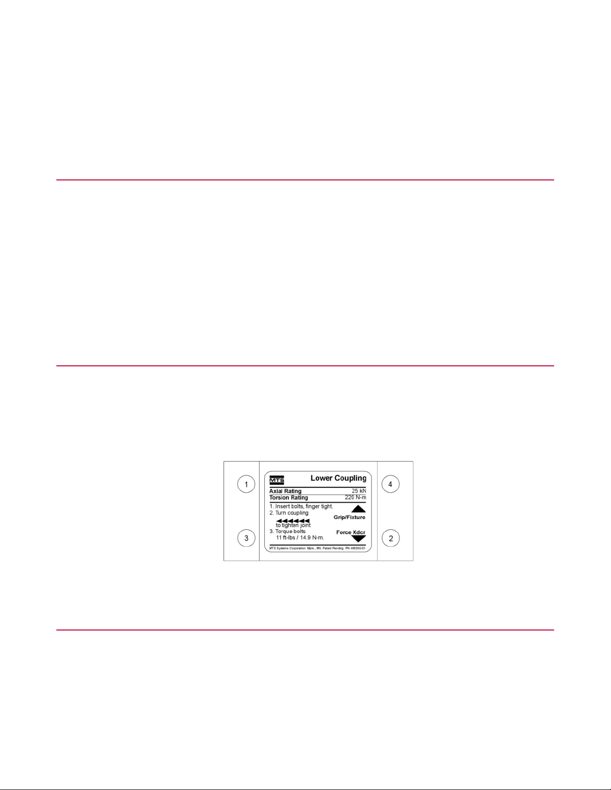
About Couplings
Special upper and lower couplings clamp the grips to the actuator and force transducer for axial-torsional
grips. Each coupling has two different thread patterns—a right-hand thread with a 3 mm pitch, and a left-hand
thread with a 2 mm pitch. Half of the coupling matches the thread of the grip, and the other half matches the
thread of the actuator or force transducer adapter. A label on each coupling indicates the direction to tighten,
torque rotation, and torque requirements. Here is an example:
About All Temperature Grips
The grip mechanism (the wedge chamber and wedges) is fully enclosed in the environmental chamber to
secure the specimen under test. The grip actuating mechanism (the end cap, preload chamber, and piston)
is outside the environmental chamber, eliminating the need for high-temperature hydraulic fluid and allowing
a broader temperature range for testing—from -129° to +315°C (-200° to +600°F) or -129° to +540°C (-200°
to +1000°F) depending on the grip model. With the grip mechanism inside the environmental chamber, the
thermal stresses caused by temperature gradients along the length of the specimen are minimized. The grip
actuating mechanism is water cooled/warmed to further protect it from temperature extremes.
Series 647 Hydraulic Wedge Grips Reference Manual 21

Introduction
About Environmental Chambers
The grips can be mounted for room temperature testing or testing in an environmental chamber. The
temperature range of the grips is determined by the type of seals used in the grips and the type of fluid used
for the grips. There are two methods for using grips in an environmental chamber (as shown in the following
figure).
DescriptionItem
Using Extension Rods with Axial GripsA
Using All Temperature GripsB
22 Series 647 Hydraulic Wedge Grips Reference Manual

Hydraulic Fluid Recommendations
All frame mounted 3000 psi and 10,000 psi grip supplies use standard Mobile DTE-25 hydraulic fluid from
the HPU. The grips that use this fluid are rated to 65 °C (150 °F) maximum. All other hydraulic grips that are
used within a chamber are rated to maximum of 177 °C (350 °F). These grips require the use of a stand alone
grip supply that uses Mobile SHS 525 hydraulic fluid. This fluid has a flash point and overall temperature
rating higher than 177 °C (350 °F). MTS does not recommend the use of hydraulic grips that have hydraulic
fluid inside chambers rated at higher temperatures.
Cooling Water Specifications
SpecificationParameter
35°C (95°F) maximumTemperature
Introduction
3.8 L/min (1 gpm) minimum, at 0.276 MPa (40 psi)Flow
Quality
Water chemistry is critical for a successful grip cooling. Generally speaking, municipal
drinking water that is pollution free, bacteriologically safe, and has a neutral pH is
perfectly acceptable for grip cooling.
Series 647 Wedge Grip Temperature Ranges
The temperature range of the grips is determined by the type of seals used in the grips and the type of
hydraulic fluid used with the grips. The grips are available in the following temperature ranges:
• -40°C to 177°C (-40°F to 350°F)
• -130°C/315°C (-200°F/600°F)
• -130°C/540°C (-200°F/1000°F)
Not all grip models are available in all temperature ranges.
Series 647 Hydraulic Wedge Grips Reference Manual 23

Introduction
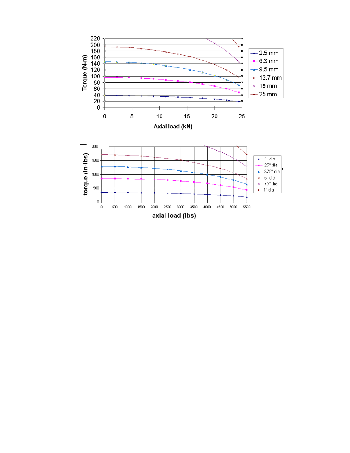
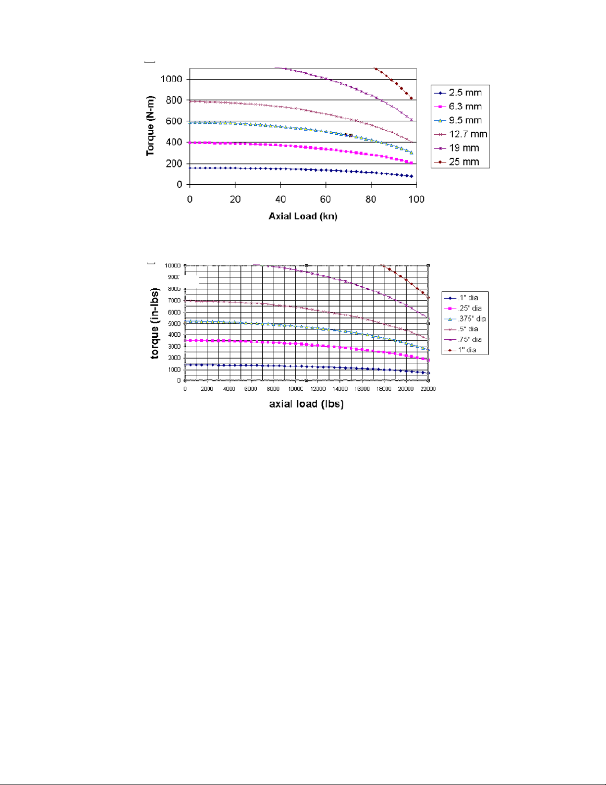
Series 647 Hydraulic Wedge Grip Force and Torque Capacities
The amount of torque the grips can produce is reduced with biaxial operation. The amount of torque is affected
by the amount of axial force and the diameter of the specimen. The graphs, which follow the table, illustrate
the axial-torsional performance envelope of the Model 647.02B and Model 647.10 Hydraulic Wedge Grips
and the Model 647.25 Axial-Torsional Wedge Grips.
Note:
Charts assume that edges for RND specimens are diamond face vee or RND wedges.
Grip PressureDynamic ForceStatic ForceModel
1
2
3
21 MPa (3,000 psi)25 kN (5.5 kip)31 kN (7 kip)647.02B
21 MPa (3,000 psi)100 kN (22 kip)120 kN (27 kip)647.10
69 MPa (10,000 psi)250 kN (55 kip)333 kN (75 kip)647.25
69 MPa (10,000 psi)500 kN (110 kip)550 kN (120 kip)647.50
69 MPa (10,000 psi)1000 kN (220 kip)1200 kN (264 kip)647.100
1
Torsional force for the axial-torsional version is 220 N·m (2,000 in·lb).
2
Torsional force for the axial-torsional version can be 550 N·m (5,000 in·lb) or 1100 N·m (10,000 in·lb).
3
Torsional force for the axial-torsional version is 2200 N·m (20,000 in·lb).
24 Series 647 Hydraulic Wedge Grips Reference Manual
Introduction
Model 647.02B Grip Maximum Torque versus Axial Load
Series 647 Hydraulic Wedge Grips Reference Manual 25
Introduction
Model 647.10 Grip Maximum Torque versus Axial Load
26 Series 647 Hydraulic Wedge Grips Reference Manual

Introduction
Model 647.25 Grip Maximum Torque versus Axial Load
Series 647 Hydraulic Wedge Grips Reference Manual 27


Safety
Topics:
•
General Safety Practices: Grips and Fixtures........................................................................................30
•
General Precautions for Environmental Components...........................................................................35
•
Hazard Placard Placement....................................................................................................................36
Series 647 Hydraulic Wedge Grips Reference Manual 29
Loading...