


 Loading...
lProduct Manual
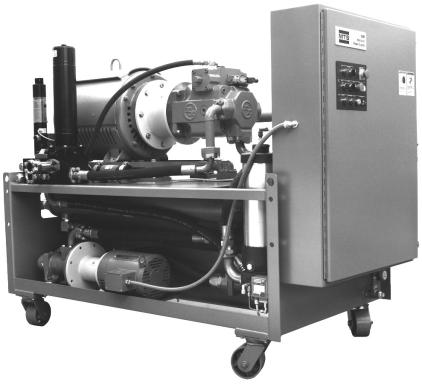
Model 506.62/.72
Hydraulic Power Supply
September 1996 117730-00D
© 1996 MTS Systems Corporation. All rights reserved.
Table of Contents
Section |
1 |
Introduction |
|
|
1.1 |
|
Functional Description ............................................................................. |
|
1-1 |
1.2 |
|
Specifications.......................................................................................... |
|
1-2 |
Section |
2 |
Operation |
|
|
2.1 |
|
Controls and Indicators............................................................................. |
|
2-1 |
2.2 |
|
Operation Procedures ............................................................................... |
|
2-3 |
2.3 |
|
Supercharge Pump Operation ................................................................... |
|
2-4 |
Section |
3 |
Service |
|
|
3.1 |
|
Maintenance Procedures............................................................................ |
|
3-1 |
3.1.1 |
|
Filters ............................................................................................... |
|
3-2 |
3.1.1.1 |
|
High-Pressure Filter Replacement................................................ |
|
3-2 |
3.1.1.2 |
|
Low-Pressure Filter Replacement.................................................. |
|
3-4 |
3.1.2 |
|
Hydraulic Fluid................................................................................. |
|
3-5 |
3.1.3 |
|
Accumulators ..................................................................................... |
|
3-7 |
3.1.3.1 |
|
Precharge Pressure-Checking Intervals......................................... |
|
3-7 |
3.1.3.2 |
|
Precharging the Accumulators ...................................................... |
|
3-7 |
3.1.3.3 |
|
Changing the Accumulator Seals .................................................. |
|
3-7 |
3.2 |
|
Service Adjustments ................................................................................. |
|
3-8 |
3.2.1 |
|
Output Pressure Adjustment ................................................................ |
|
3-9 |
3.2.2 |
|
Dual-Temperature Switch Adjustments............................................. |
|
3-10 |
3.2.3 |
|
Low-Level Switch Adjustment.......................................................... |
|
3-11 |
3.2.4 |
|
Main Pump Low-Inlet Pressure Switch Adjustment............................. |
|
3-12 |
3.3 |
|
Starter Assembly ................................................................................... |
|
3-13 |
3.3.1 |
|
Abnormal HPS Shutdown................................................................. |
|
3-14 |
3.3.2 |
|
Fuse Replacement............................................................................. |
|
3-14 |
3.3.3 |
|
PLC ..................................................................................... |
Service |
3-15 |
Section |
4 |
Installation |
|
|
4.1 |
|
Hydraulic Connections ............................................................................. |
|
4-2 |
4.2 |
|
Electrical Connections .............................................................................. |
|
4-3 |
4.2.1 |
|
Transformer Wiring............................................................................ |
|
4-4 |
4.2.2 |
|
Input Power........................................................................................ |
|
4-5 |
4.3 |
|
Cooling Water Connections....................................................................... |
|
4-6 |
Table of Contents |
i |
Section 5 |
Theory of Operation |
|
5.1 |
Hydraulic Operation ............................................................................... |
5-1 |
5.2 |
Electrical Operation ................................................................................ |
5-3 |
5.2.1 |
Control .............................................................................................. |
5-3 |
5.2.2 |
Interlocks........................................................................................... |
5-5 |
Index
List of Figures
Figure 2-1 |
Controls and Indicators ............................................................................ |
2-1 |
Figure 3-1 |
Location of Maintenance Components (HPS Side View) ............................. |
3-1 |
Figure 3-2 |
Location of Adjustment Components (HPS Side View)................................ |
3-8 |
Figure 3-3 |
Model 506.62/.72 Starter Assembly......................................................... |
3-13 |
Figure 4-1 |
Location of Remote Connector.................................................................... |
4-1 |
Figure 4-2 |
Hydraulic Connections ............................................................................. |
4-2 |
Figure 4-3 |
Model 506.62/.72 Starter Assembly........................................................... |
4-3 |
Figure 4-4 |
Standard Transformer Wiring Configuration............................................. |
4-4 |
Figure 4-5 |
Typical Multi-Tap Transformer Wiring Configuration............................... |
4-4 |
Figure 4-6 |
Heat Exchanger Connections..................................................................... |
4-6 |
Figure 5-1 |
Hydraulic Block Diagram........................................................................ |
5-1 |
Figure 5-2 |
Typical Electrical Schematic ................................................................... |
5-6 |
List of Tables
Table 1-1 |
Cooling Water Flow Requirements |
............................................................1-2 |
|
Table 1-2 |
HPS Specifications .................................................................................. |
1-3 |
|
Table 2-1 |
Controls and |
Indicators............................................................................. |
2-2 |
Table 3-1 |
Maintenance |
Schedule.............................................................................. |
3-2 |
Table 3-2 |
Starter Assembly Fuse Values................................................................. |
3-14 |
|
ii Table of Contents
|
Section 1 |
|
Introduction |
Definition |
The Model 506.62/.72 Hydraulic Power Supply (HPS) uses a variable- |
|
volume (pressure compensated) main pump, with a pressurized |
|
(supercharged) hydraulic fluid inlet, to provide pressure to systems |
|
with various flow requirements. The HPS is designed to be used with |
|
servo-controlled, electro-hydraulic systems. |
019-341M
1.1 Functional Description
Front panel controls and indicators
Pressure output
Front panel controls on the HPS include local operating controls for the main pump and supercharge pump. Front panel indicators show running time, power on, low fluid level, fluid over-temperature, and dirty filter conditions.
Pressure output is controlled by an adjustment on the main pump and is monitored by the output pressure gage. An adjustable back-up relief valve limits output pressure by porting fluid back to the reservoir when the output pressure rises above the relief valve setting. High/low pressure operation is controlled by the high/low solenoid valves. These valves control the main pressure control (pressure compensator) vent ports and the backup relief valve vent port.
Introduction 1-1
Pressure accumulation |
The pump-outlet pressure accumulator smooths the HPS output and |
|
provides additional hydraulic pressure for high instantaneous flow |
|
demands. It is precharged with dry nitrogen to a pressure proportional |
|
to HPS output pressure. The optional slow turn-on accumulator slows |
|
the rate at which the backup relief valve shifts from low to high |
|
pressure. |
Temperature control |
A temperature gage indicates hydraulic fluid temperature. An |
|
oil-to-water heat exchanger controls the fluid temperature. When the |
|
temperature exceeds a preset limit, a temperature sensitive switch |
|
turns off the HPS and lights the front panel Fluid Over-Temperature |
|
indicator. |
Fluid level indication |
A transparent gage indicates the level of hydraulic fluid in the HPS |
|
reservoir. A low-level switch automatically turns off the HPS and |
|
lights the front panel Low Fluid Level indicator if hydraulic fluid |
|
drops below a preset level. |
Programmable logic controller
The PLC (programmable logic controller) located in the starter assembly performs logic functions. The I/O (input/output) section of the PLC provides an interface for various signals received from or sent to external devices.
1.2 Specifications
Cooling water specifications
The required water pressure between the input and the output of the
heat exchanger is 30 to 45 psi (0.2 to 0.3 MPa). The maximum allowable pressure is 120 psi (0.8 MPa). The flow rate (±20%) at a given
temperature is shown in the table below.
Table 1-1. Cooling Water Requirements
Cooling Water Inlet |
Required Water Flow |
|
Temperature |
506.62 |
506.72 |
60°F (15.5°C) |
30 gpm (114 L/min) |
35 gpm (132 L/min) |
65°F (18.5°C) |
35 gpm (132 l/min) |
42 gpm (159 L/min) |
70°F (21.0°C) |
40 gpm (151 Ll/min) |
51 gpm (193 L/min) |
75°F (24.0°C) |
40 gpm (151 L/min) |
67 gpm (254 L/min) |
80°F (26.5°C) |
45 gpm (170 L/min) |
90 gpm (341 L/min) |
85°F (29.5°C) |
63 gpm (238 L/min) |
120 gpm (454 L/min) |
1-2 Introduction

HPS specifications |
Table 1-2 lists the specifications for the Model 506.62/.72 HPS. |
||
|
Table 1-2. HPS Specifications |
|
|
Parameter |
Model 506.62 |
Model 506.72 |
|
Maximum continuous pressure |
3000 psi (21 MPa) |
3000 psi (21 MPa) |
|
Maximum flow capacity |
|
75 gpm (284 L/min) |
100 gpm (380 L/min) |
Noise rating at 3 ft. (0.9 m) |
|
90 dBa |
90 dBa |
Reservoir capacity: |
|
200 gpm (757 L) |
280 gpm (1074 L) |
Low-pressure filtration, absolute/nominal |
3.0/0.45 microns |
3.0/0.45 microns |
|
High-pressure filtration |
|
10 microns |
10 microns |
Fluid hose connections:* |
|
|
|
Pressure (SAE 4 bolt) |
|
-20 (1), -24 (1) |
-20 (1), -24 (1) |
Return (SAE 4 bolt) |
|
-20 (1), -24 (1) |
-20 (1), -24 (1) |
Drain (37° flare) |
|
-12 (2), -16 (1) |
-12 (2), -16 (1) |
Main pump motor power rating (2 each) |
150 hp (112 kW) |
200 hp (150 kW) |
|
Supercharge pump motor power rating |
15 hp (11 kW) |
20 hp (15 kW) |
|
3-phase current 460V/60 Hz:† |
|
|
|
Inrush |
|
385 A |
515 A |
Continuous |
|
200 A |
250 A |
Starter type (main pump motor) |
Wye-delta |
Wye-delta |
|
24 V external hydraulic control amps, 60 Hz |
9 A |
9 A |
|
Maximum cooling water heat load: |
|
|
|
BTU per hour |
|
380,000 |
509,000 |
Kilocalories per hour |
|
96,000 |
128,600 |
Atmospheric heat load |
|
|
|
BTU per hour |
|
27,600 |
37,000 |
Kilocalories per hour |
|
7,000 |
11,100 |
Water inlet/outlet size |
|
1.25 in. (38.8 mm) I.D. |
1.25 in. (38.8 mm) I.D. |
Maximum ambient operating temperature |
104°F (40°C) |
104°F (40°C) |
|
Minimum ambient operating temperature |
40°F (4.4°C) |
40°F (4.4°C) |
|
Height with casters |
|
68 in. (1727 mm) |
78 in. (1981 mm) |
Length |
|
90 in. (2286 mm) |
90 in. (2286 mm) |
Width |
|
45 in. (1143 mm) |
45 in. (1143 mm) |
Weight with oil |
|
6000 lb (2722 kg) |
6,500 lb (2948 kg) |
*The number of connections are shown in parentheses.
†Currents listed are typical values. Maximum values may be as much as 10 to 15% higher.
Specifications are subject to change without notice. Contact MTS for verification of any critical specifications.
Introduction 1-3

Section 2
Operation
2.1 Controls and Indicators
The controls and indicators provided with the Model 506.62/.72 Hydraulic Power Supply (HPS) are described in Table 2-1. The locations of these components are identified in the following figure.
|
Power |
|
Spch Pump |
|
Emergency Stop |
|
|
|
Run |
Start |
|
|
|
|
Auto |
|
|
1 |
|
|
|
|
11 |
2 |
|
|
|
|
|
HPS |
Source |
|
Main Pump |
Stop |
Reset |
Control |
|
|
Low |
|
|
|
Remote |
Local |
High |
Start |
|
3 |
|
|
|
10 |
4 |
|
|
|
9 |
Conditions |
Fluid Low Level |
Fluid Over-Temp |
Dirty Filter |
Hours of Operation |
|
5 |
6 |
7 |
8 |
|
|
|
|
12 |
|
|
|
|
13 |
|
|
|
|
VW-G041C |
Figure 2-1. Controls and Indicators
Operation 2-1

|
|
Table 2-1. Controls and Indicators |
Item |
Control/Indicator |
Description |
1 |
Power indicator* |
The Power indicator lights to indicate that electrical power is |
|
|
applied to the HPS. |
2 |
Spch Pump |
To operate the supercharge pump when the main pump is not |
|
Auto/Run/Start switch |
operating, turn this spring-loaded switch to Start. After the |
|
|
switch is released, it returns to the Run position — indicating |
|
|
that the supercharge pump is circulating hydraulic fluid through |
|
|
the heat exchanger and fine filter. If the switch is in the Auto |
|
|
position, the HPS can be controlled by either the High/ |
|
|
Low/Start switch or the optional remote control panel. |
3 |
Source Remote/Local |
If this two-position switch is in the Local position, you can |
|
switch |
operate the HPS with the front panel controls. If it is in the |
|
|
Remote position, use a remote control device to operate the HPS. |
4 |
Main Pump |
To apply low pressure in local control, turn this spring-loaded |
|
High/Low/Start switch |
switch to Start. After the switch is released, it returns to the |
|
|
Low position — indicating low pressure operation. Turn the |
|
|
switch to High to select high pressure. |
5 |
Low Fluid Level |
When this indicator lights, the hydraulic fluid level has |
|
indicator* |
dropped below a preset value. |
6 |
Fluid Over-Temperature |
When this indicator lights, hydraulic fluid temperature has |
|
indicator* |
exceeded a preset value. |
7 |
Dirty Filter indicator* |
When this indicator lights, the low-pressure filter needs |
|
|
replacement. See Subsection 3.1.1. |
8 |
Hours of Operation |
This front panel meter indicates the total operating hours of the |
|
meter |
pump. |
9 |
Stop switch |
When Stop is pressed (in either local and remote control), the |
|
|
HPS output first ramps to low pressure and then goes to zero |
|
|
pressure. The supercharge pump continues to run for |
|
|
approximately 10 seconds. |
10 |
Reset switch |
This switch resets the interlock circuit if the condition causing |
|
|
the interlock has been corrected. |
11 |
Emergency Stop switch |
This switch operates in both local and remote control and is used |
|
|
during emergency situations only. When pressed, it immediately |
|
|
shuts down the HPS (the supercharge pump may continue to run |
|
|
briefly to supply the main pump until they fully stop). |
12 |
Fluid level gage |
This gage indicates the level of hydraulic fluid in the reservoir. |
13 |
Temperature gage |
This gage indicates the temperature of the hydraulic fluid in the |
|
|
HPS reservoir. |
*Indicators are "push-to-test" type indicators. This means that if you push the indicator, it will light. If it does not light, the bulb is burned out.
2-2 Operation
2.2 Operation Procedures
This section provides the local and remote operating procedures for the 506.62/.72 Hydraulic Power Supply.
! WARNING
Warning
Do not start the HPS if the servovalve command is not equal to feedback (that is, zero balanced).
Failure to do this can result in sudden actuator movement which may cause injury to persons and/or damage to equipment.
Ensure that the system is at zero balance before starting the HPS.
Before you begin |
Make sure that the external hydraulic system is ready for operation. |
N O T E The Dirty Filter indicator may light during a coldstart. It should turn off when the HPS reaches its normal operating temperature. If the indicator fails to turn off, correct the condition (Subsection 3.1.1.2) and press Reset.
Local operation |
1. |
Turn the Source Remote/Local switch to Local. |
|
2. |
Apply electrical power to the HPS (the Power indicator will |
|
|
light). |
|
3. |
Press Reset.1 |
|
4. |
Momentarily turn the High/Low/Start switch to Start. When you |
|
|
release the switch, it returns to Low. |
|
5. |
Check the HPS and external hydraulic system for leaks and |
|
|
unusual sounds. |
|
6. |
Turn the High/Low/Start switch to High to apply high pressure. |
|
7. |
Press Stop on the HPS front panel to stop the HPS and remove |
|
|
output pressure. |
1 |
Reset must be pressed whenever electrical power to the HPS has been interrupted. |
|
Operation 2-3
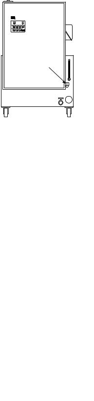
Remote Operation
Remote control |
connector |
1.Turn the Source Remote/Local switch to Remote. Make sure that the remote control cable is connected to the cable connector (the figure on the left shows the location of this connector) and to the remote control device.
2.Apply electrical power.
3.Press Reset.1
4.Use the remote control device to start the HPS at low pressure.
5.Check for leaks and unusual sounds.
6.Select high pressure at the remote control device.
7.Use the Off switch on the remote control device to stop the HPS and remove output pressure.
2.3 Supercharge Pump Operation
When to use the supercharge pump
When the temperature of the hydraulic fluid in the HPS reservoir exceeds 140˚F (60˚C), the fluid over-temperature switch automatically shuts down the HPS. The HPS main pumps cannot be restarted in local or remote until the hydraulic fluid cools. The following procedure uses the supercharge pump to hasten the cooling of the hydraulic fluid.
Cooling procedure |
1. |
Ensure the water supply to the heat exchanger is turned on. |
|
2. |
Turn the Spch Pump switch to the Start position and then release |
|
|
the switch and allow it to return to the Run position. The |
|
|
supercharge pump operates independently of the main pumps and |
|
|
circulates hydraulic fluid through the heat exchanger to cool the |
|
|
fluid. |
|
3. |
When the temperature gage reads approximately 130˚F (54˚C), |
|
|
turn the Spch Pump switch to the Auto position (the supercharge |
|
|
pump will stop). |
|
4. |
To restart the HPS, first press the Reset control on the local or |
|
|
remote control panel to clear the hydraulic interlock circuit, and |
|
|
then start the HPS in low pressure. |
1 |
Reset must be pressed whenever electrical power to the HPS has been interrupted. |
|
2-4 Operation
Section 3
Service
Introduction |
This section contains service information for the Model 506.62/.72 |
|
Hydraulic Power Supply (HPS). It provides: |
•maintenance procedures
•service adjustments
•electrical information
3.1 Maintenance Procedures
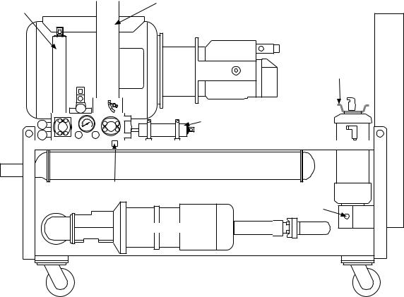
Maintenance overview The following subsections provide the routine maintenance procedures for the HPS. Figure 3-1 shows the location of the components accessed for the maintenance procedures. Table 3-1 lists the maintenance schedule.
High Pressure
Pressure  Filter
Accumulator
Low Pressure
Filter
Slow Turn-on |
Accumulator |
Heat Exchanger |
Manifold Drain |
(under manifold) |
Filter |
Drain |
Supercharge Pump |
VW-G069
Figure 3-1. Location of Maintenance Components (HPS Side View)
Service 3-1
Table 3-1. Maintenance Schedule |
|
|
Procedure |
Interval |
Subsection |
Check output pressure on gage* |
daily |
|
Replace high-pressure filter |
when the indicator points to CHANGE |
3.1.1 |
Replace low-pressure filter |
when Dirty Filter indicator lights |
3.1.1 |
Check hydraulic fluid level on gage |
daily |
3.1.2 |
Check hydraulic fluid in reservoir |
150 operating hours |
3.1.2 |
Analyze hydraulic fluid |
500 operating hours |
3.1.2 |
Check accumulator precharge |
at established interval |
3.1.3 |
Check hydraulic hoses |
monthly |
|
*See Subsection 3.2.1 to adjust the output pressure.
3.1.1 Filters
Fluid filtration is provided by a 10-micron high-pressure filter and a 3-micron low-pressure filter. See Figure 3-1 for the location of the filters and their drains.
! WARNING
High-pressure release occurs if the system is pressurized.
High-pressure release may cause personal injury or damage equipment.
Ensure that the output pressure gage reads zero before replacing the filters.
3 . 1 . 1 . 1 High-Pressure Filter Replacement
CHANGE
OK
DIRT ALARM
VW-GO46
Replace the high-pressure filter elements whenever the DIRT ALARM indicator mounted on the base of each high-pressure filter housing points to CHANGE (red or yellow zone) or whenever the hydraulic fluid is replaced.
1.Press Stop on the HPS. The output pressure gage must read zero.
3-2 Service
Loading...