


 Loading...
Multipurpose Elite Test Design Guide
For MTS Acumen™ Electrodynamic Test Systems
100-268-627 B |
be certain. |
© 2013 MTS Systems Corporation. All rights reserved.
Trademark Information
MTS, FlexTest, RPC, and TestWare are registered trademarks and MTS Acumen, MTS TestSuite, Station Builder, and Station Manager are trademarks of MTS Systems Corporation within the United States. These trademarks may be protected in other countries. All other trademarks are the property of their respective owners.Microsoft and Windows NT are registered trademarks of Microsoft Corporation. All other trademarks or service marks are property of their respective owners.
Proprietary Software
Software use and license is governed by MTS’s End User License Agreement which defines all rights retained by MTS and granted to the End User. All Software is proprietary, confidential, and owned by MTS Systems Corporation and cannot be copied, reproduced, disassembled, decompiled, reverse engineered, or distributed without express written consent of MTS.
Software Verification and Validation
MTS software is developed using established quality practices in accordance with the requirements detailed in the ISO 9001 standards. Because MTS-authored software is delivered in binary format, it is not user accessible. This software will not change over time. Many releases are written to be backwards compatible, creating another form of verification. The status and validity of MTS’s operating software is also checked during system verification and routine calibration of MTS hardware. These controlled calibration processes compare the final test results after statistical analysis against the predicted response of the calibration standards. With these established methods, MTS assures its customers that MTS products meet MTS’s exacting quality standards when initially installed and will continue to perform as intended over time.
Manual Part Number—Publication Date—Release
100-268-627 B—August 2013—TestSuite MP 2.6 or later
100-268-627 A—January 2013—TestSuite MP 2.5
Contents |
|
1.0 Technical Support |
7 |
1.1.0 How to Get Technical Support........................................................................................................ |
7 |
1.2.0 Before You Contact MTS................................................................................................................ |
7 |
1.3.0 If You Contact MTS by Phone........................................................................................................ |
9 |
1.4.0 Problem Submittal Form in MTS Manuals................................................................................... |
10 |
2.0 Preface |
11 |
2.1.0 Before You Begin.......................................................................................................................... |
11 |
2.2.0 Documentation Conventions......................................................................................................... |
11 |
3.0 Designing a Test |
15 |
3.1.0 Introduction................................................................................................................................... |
16 |
3.2.0 Test Design WorkFlow.................................................................................................................. |
16 |
3.2.1.0 Using the Multipurpose Application with Controller Software..................................... |
17 |
3.2.1.1.0 Launching MPE or MPX................................................................................. |
17 |
3.2.1.2.0 Creating a Desktop Shortcut That Includes a Controller................................ |
18 |
3.2.1.3.0 Multipurpose Application Startup Overview.................................................. |
18 |
3.2.2.0 Creating Tests Overview................................................................................................ |
19 |
3.2.3.0 Test Activities Overview................................................................................................ |
19 |
3.2.3.1.0 Deleting and Disabling Test Activities............................................................ |
21 |
3.2.3.2.0 Variables Overview......................................................................................... |
22 |
3.2.3.3.0 Information for an Operator............................................................................ |
23 |
3.2.4.0 Working with Test-Run Display Devices....................................................................... |
24 |
3.2.5.0 Test Execution Overview............................................................................................... |
24 |
3.2.6.0 Test Design Considerations............................................................................................ |
26 |
3.2.6.1.0 Consider Your Station Setup........................................................................... |
26 |
3.2.6.2.0 C-Stop (Controlled Stop) Interlock Action..................................................... |
27 |
3.2.6.3.0 Using Stop Actions Within a Test................................................................... |
28 |
3.2.7.0 Generating a Report in MP............................................................................................. |
28 |
3.2.8.0 Generating a Report Using the Excel Reporter Add-In................................................. |
28 |
4.0 Working with Resources |
31 |
4.1.0 Resources...................................................................................................................................... |
32 |
4.2.0 Starting MPE and Connecting to a Controller............................................................................... |
32 |
4.3.0 Resource Mapping......................................................................................................................... |
34 |
4.4.0 Offline Test Design....................................................................................................................... |
35 |
4.5.0 Resources That Allow Dimension Changes.................................................................................. |
37 |
Multipurpose Elite Test Design Guide 3
5.0 Creating Tests |
39 |
5.1.0 Installing MTS TestSuite Simulation Software............................................................................. |
40 |
5.2.0 Creating Ramp and Cycle Test...................................................................................................... |
40 |
5.2.1.0 Ramp and Cycle Test Design Overview......................................................................... |
40 |
5.2.2.0 Opening a Station Configuration and Starting the MPE Application............................ |
42 |
5.2.3.0 Creating an Empty Test.................................................................................................. |
43 |
5.2.4.0 Adding a Ramp Activity................................................................................................. |
43 |
5.2.5.0 Adding a Cycle Activity................................................................................................. |
44 |
5.2.6.0 Adding a Second Ramp Activity.................................................................................... |
46 |
5.2.7.0 Adding a Signal Scope Monitor..................................................................................... |
47 |
5.2.8.0 Checking the Test Procedure.......................................................................................... |
49 |
5.2.9.0 Adding Variables............................................................................................................ |
50 |
5.2.10.0 Adding an Input Variables Activity.............................................................................. |
52 |
5.2.11.0 Adding Parallel Paths and a Data Acquisition Activity............................................... |
53 |
5.2.12.0 Running the Test Procedure......................................................................................... |
56 |
6.0 Creating Advanced Tests |
59 |
6.1.0 Introduction................................................................................................................................... |
60 |
6.2.0 Working with Profiles................................................................................................................... |
60 |
6.2.1.0 Profile Test Overview..................................................................................................... |
61 |
6.2.2.0 Controls That Affect Profiles......................................................................................... |
62 |
6.2.3.0 Creating a Profile............................................................................................................ |
63 |
6.2.4.0 Creating Controller Resource Actions that Map to the Profile...................................... |
64 |
6.2.5.0 Starting the MPE Application and Creating a New Test Shell....................................... |
66 |
6.2.6.0 Adding a Profile Activity............................................................................................... |
66 |
6.2.7.0 Adding a Monitor Display to Show the Profile Waveform............................................ |
68 |
6.2.8.0 Adding a Monitor Display to Track Profile Passes........................................................ |
69 |
6.2.9.0 Adding a Monitor Display to Show When Part of the Profile Plays Out....................... |
69 |
6.2.10.0 Start the Test Procedure and Observe the Response.................................................... |
70 |
6.2.11.0 Considerations for Profile Design................................................................................ |
72 |
6.2.11.1.0 Profile Types.................................................................................................. |
72 |
6.2.11.2.0 Using ALC with the Profile Activity............................................................. |
72 |
6.2.11.3.0 General Profile Syntax Requirements........................................................... |
74 |
6.2.11.4.0 Header Data Syntax....................................................................................... |
74 |
6.2.11.5.0 Action and Counter Syntax........................................................................... |
75 |
6.2.11.6.0 Channel Header Syntax................................................................................. |
76 |
6.2.11.7.0 Channel Data Syntax..................................................................................... |
77 |
6.2.11.8.0 Dimensions.................................................................................................... |
79 |
6.2.11.9.0 Normalized Dimensions................................................................................ |
80 |
4 Multipurpose Elite Test Design Guide
7.0 MTS Controller Software |
83 |
7.1.0 Software Concepts......................................................................................................................... |
84 |
7.1.1.0 Key Concepts about Using MTS TestSuite and Controller Software............................ |
84 |
7.2.0 Adding Station Resources............................................................................................................. |
85 |
7.2.1.0 Adding Existing Hardware Resources to a Station Configuration................................. |
85 |
7.2.2.0 Adding New Hardware to a Controller.......................................................................... |
86 |
8.0 Appendix A: MPE for MPT Users |
87 |
8.1.0 About This Appendix.................................................................................................................... |
88 |
8.2.0 Major Concepts............................................................................................................................. |
88 |
8.3.0 Control Panel and Options............................................................................................................ |
91 |
8.4.0 Editing Features............................................................................................................................. |
92 |
8.5.0 Command...................................................................................................................................... |
93 |
8.6.0 Data Acquisition............................................................................................................................ |
95 |
8.7.0 Event Detectors............................................................................................................................. |
98 |
8.8.0 External Control............................................................................................................................ |
99 |
8.9.0 Performance................................................................................................................................ |
100 |
8.10.0 General...................................................................................................................................... |
100 |
8.11.0 Other.......................................................................................................................................... |
101 |
Multipurpose Elite Test Design Guide 5

1.0 Technical Support
1.1.0 How to Get Technical Support
Start with your manuals
The manuals supplied by MTS provide most of the information you need to use and maintain your equipment. If your equipment includes software, look for online help and README files that contain additional product information.
Technical support methods
MTS provides a full range of support services after your system is installed. If you have any questions about a system or product, contact Technical Support in one of the following ways.
Web site |
www.mts.com > Contact Us (upper-right corner) > In the Subject field, choose |
|
To escalate a problem; Problem Submittal Form |
Worldwide: tech.support@mts.com |
|
|
Europe: techsupport.europe@mts.com |
Telephone |
Worldwide: 1 800 328 2255 - toll free in U.S.; +1 952 937 4000 - outside U.S. |
|
Europe: +800 81002 222, International toll free in Europe |
Outside the U.S.
For technical support outside the United States, contact your local sales and service office. For a list of worldwide sales and service locations and contact information, use the Global MTS link at the MTS web site:
www.mts.com > Global Presence > Choose a Region
1.2.0 Before You Contact MTS
MTS can help you more efficiently if you have the following information available when you contact us for support.
Multipurpose Elite Test Design Guide 7
Know your site number and system number
The site number contains your company number and identifies your equipment type (such as material testing or simulation). The number is typically written on a label on your equipment before the system leaves MTS. If you do not know your MTS site number, contact your sales engineer.
Example site number: 571167
When you have more than one MTS system, the system job number identifies your system. You can find your job number in your order paperwork.
Example system number: US1.42460
Know information from prior technical assistance
If you have contacted MTS about this problem before, we can recall your file based on the:
•MTS notification number
•Name of the person who helped you
Identify the problem
Describe the problem and know the answers to the following questions:
•How long and how often has the problem occurred?
•Can you reproduce the problem?
•Were any hardware or software changes made to the system before the problem started?
•What are the equipment model numbers?
•What is the controller model (if applicable)?
•What is the system configuration?
Know relevant computer information
For a computer problem, have the following information available:
•Manufacturer’s name and model number
•Operating software type and service patch information
•Amount of system memory
•Amount of free space on the hard drive where the application resides
•Current status of hard-drive fragmentation
•Connection status to a corporate network
Know relevant software information
For software application problems, have the following information available:
•The software application’s name, version number, build number, and (if available) software patch number. This information can typically be found in the About selection in the Help menu.
•The names of other applications on your computer, such as:
•Anti-virus software
•Screen savers
8 Multipurpose Elite Test Design Guide

•Keyboard enhancers
•Print spoolers
•Messaging applications
1.3.0 If You Contact MTS by Phone
A Call Center agent registers your call before connecting you with a technical support specialist. The agent asks you for your:
•Site number
•Name
•Company name
•Company address
•Phone number where you can be reached
If your issue has a notification number, please provide that number. A new issue will be assigned a unique notification number.
Identify system type
To enable the Call Center agent to connect you with the most qualified technical support specialist available, identify your system as one of the following types:
•Electrodynamic material test system
•Electromechanical material test system
•Hydromechanical material test system
•Vehicle test system
•Vehicle component test system
•Aero test system
Be prepared to troubleshoot
Prepare to perform troubleshooting while on the phone:
•Call from a telephone close to the system so that you can implement suggestions made over the phone.
•Have the original operating and application software media available.
•If you are not familiar with all aspects of the equipment operation, have an experienced user nearby to assist you.
Write down relevant information
In case Technical Support must call you:
•Verify the notification number.
•Record the name of the person who helped you.
Multipurpose Elite Test Design Guide 9

•Write down any specific instructions.
After you call
MTS logs and tracks all calls to ensure that you receive assistance for your problem or request. If you have questions about the status of your problem or have additional information to report, please contact Technical Support again and provide your original notification number.
1.4.0 Problem Submittal Form in MTS Manuals
Use the Problem Submittal Form to communicate problems with your software, hardware, manuals, or service that are not resolved to your satisfaction through the technical support process. The form includes check boxes that allow you to indicate the urgency of your problem and your expectation of an acceptable response time. We guarantee a timely response—your feedback is important to us.
You can access the Problem Submittal Form at www.mts.com > Contact Us (upper-right corner) > In the
Subject field, choose To escalate a problem; Problem Submittal Form
10 Multipurpose Elite Test Design Guide
2.0 Preface
2.1.0 Before You Begin
Safety first!
Before you use your MTS product or system, read and understand the safety information provided with your system. Improper installation, operation, or maintenance can result in hazardous conditions that can cause severe personal injury or death, or damage to your equipment and specimen. Again, read and understand the safety information provided with your system before you continue. It is very important that you remain aware of hazards that apply to your system.
Other MTS manuals
In addition to this manual, you may receive additional manuals in paper or electronic form.
You may also receive an MTS System Documentation CD. It contains an electronic copy of the manuals that pertain to your test system.
Controller and application software manuals are typically included on the software CD distribution disc(s).
2.2.0 Documentation Conventions
The following paragraphs describe some of the conventions that are used in your MTS manuals.
Hazard conventions
Hazard notices may be embedded in this manual. These notices contain safety information that is specific to the activity to be performed. Hazard notices immediately precede the step or procedure that may lead to an associated hazard. Read all hazard notices carefully and follow all directions and recommendations.Three different levels of hazard notices may appear in your manuals. Following are examples of all three levels.
(for general safety information, see the safety information provided with your system.)
DANGER:
Danger notices indicate the presence of a hazard with a high level of risk which, if ignored, will result in death, severe personal injury, or substantial property damage.
WARNING:
Warning notices indicate the presence of a hazard with a medium level of risk which, if ignored, can result in death, severe personal injury, or substantial property damage.
Multipurpose Elite Test Design Guide 11
CAUTION:
Caution notices indicate the presence of a hazard with a low level of risk which, if ignored, could cause moderate or minor personal injury or equipment damage, or could endanger test integrity.
Other special text conventions
Important:
Important notices provide information about your system that is essential to its proper function. While not safety-related, if the important information is ignored, test results may not be reliable, or your system may not operate properly.
Note:
Notes provide additional information about operating your system or highlight easily overlooked information.
Recommended:
Recommended notes provide a suggested way to accomplish a task based on what MTS has found to be most effective.
Tip:
Tips provide helpful information or a hint about how to most efficiently accomplish a task.
Access:
Access provides the route you should follow to a referenced item in the software.
Example:
Examples show specific scenarios relating to your product and appear with a shaded background.
Special terms
The first occurrence of special terms is shown in italics.
Illustrations
Illustrations appear in this manual to clarify text. They are examples only and do not necessarily represent your actual system configuration, test application, or software.
Electronic manual conventions
This manual is available as an electronic document in the Portable Document File (PDF) format. It can be viewed on any computer that has Adobe Acrobat Reader installed.
12 Multipurpose Elite Test Design Guide
Hypertext links
The electronic document has many hypertext links displayed in a blue font. All blue words in the body text, along with all contents entries and index page numbers, are hypertext links. When you click a hypertext link, the application jumps to the corresponding topic.
Multipurpose Elite Test Design Guide 13

3.0 Designing a Test
Topics: |
|
|
• |
Introduction............................................................................................................................................ |
16 |
• |
Test Design WorkFlow........................................................................................................................... |
16 |
Multipurpose Elite Test Design Guide 15

3.0 Designing a Test
3.1.0 Introduction
About this chapter
This chapter contains information about the MPE and Station Manager software, basic test design principles, how tests are executed, and how information about test results is made available. If you already feel comfortable with these test design principles and are ready to begin creating a basic ramp and cycle test, see Creating Ramp and Cycle Test on page 40.
MTS Multipurpose Elite application overview
The MTS Multipurpose Elite (MPE) application is a sophisticated, general purpose test design application that allows you to quickly and easily define complex test designs. The role of either Administrator or Engineer is required to access full functionality of MPE. Operators are allowed to access MPE but only with the same rights they have in MPX.
Note:
MTS offers a companion application to MPE named Multipurpose Express (MPX). You cannot create or modify tests with MPX; it is only to run existing tests. In cases where this manual refers to functionality shared by both applications (such as running tests), the term “Multipurpose application” is used.
The Multipurpose Elite Test Design Guide contains the information you need to begin designing tests and test reports with the MPE application. It includes the fundamental concepts of using the MPE application with the MTS controller software to create and run tests.
This guide does not explain every MPE application feature. Its goal is to introduce the most important features of the application in the context of designing tests and test reports.
This chapter contains conceptual information pertinent to test designs. New users should read this chapter before using the software to gain an overall understanding of the design process. Experienced users can read this chapter to review the high-level activities associated with each design task. Detailed instructions to perform the tasks in this chapter are included in other parts of this guide.
3.2.0 Test Design WorkFlow
This table shows the tasks a test designer may perform to prepare a test for an operator. The order in which the tasks are shown is typical.
Typical Tasks for Preparing a Test
Step |
Activity |
Description |
1 |
Open a station configuration |
Open a station configuration file with your MTS |
|
|
controller software. |
16 Multipurpose Elite Test Design Guide

|
|
3.0 Designing a Test |
Step |
Activity |
Description |
2 |
Start the MPE application and |
With your station open, use the MPE application. |
|
select a new test |
|
3 |
Add test activities and define their |
To create a test file, drag test activity icons onto the |
|
properties |
Procedure tab. |
4 |
Add monitor display devices and |
Add monitor display devices, such as Signal Scope, |
|
define their properties |
so you can monitor test progress. |
5 |
Run the test to verify your design |
Use MTS controller software and MPE together to run |
|
|
tests. This step generates data in a test run. |
6 |
Create a test report template |
Create a test report template by adding test variables |
|
|
from your test run to a Microsoft Excel report. |
7 |
Ensure your test is ready for the |
You typically run your test again from the operator’s |
|
operator |
perspective. You can choose to enhance your test |
|
|
with special operator information. |
8 |
Deliver your test to the operator |
When the test meets your requirements, deliver it to |
|
|
the operator. You can choose to have your operators |
|
|
use MP Express to run your test. |
3.2.1.0UsingtheMultipurposeApplicationwithControllerSoftware
3.2.1.1.0 Launching MPE or MPX
Note:
If you have a desktop shortcut that opens the Station Manager application and then opens the MPE or MPX application, you do not have to perform this procedure to start the Station Manager application and load the station configuration. For more information about creating this desktop shortcut, see
Creating a Desktop Shortcut That Includes a Controller on page 18.
1.Start the Station Manager application by double-clicking the Station Manager icon located in the MTS 793 Software folder on the desktop; or from the Start menu, go to All Programs > MTS 793 Software > Station Manager. The Open Station window appears.
2.In the Open Station window, select the station configuration file (.cfg) required to run the test (MTS FlexTest 40 with 2 Channel configuration). The .cfg file defines all the station resources that are available for a test.
3.Click Open.
4.The Station Manager window appears, which can be minimized.
Multipurpose Elite Test Design Guide 17

3.0 Designing a Test
Important:
You must leave the Station Manager application open, but you can minimize it so it does not appear on your screen.
MTS TestSuite MPX is the intended operator interface. Do not make configuration changes in the Station Manager application without training from MTS.
5.Open MPE or MPX by double-clicking its icon on your desktop; or from the Start menu, go to All Programs > MTS TestSuite. The MP main window opens. You can now open a test.
Note:
If you have multiple stations, you can create individual shortcuts that are specific to each station.
3.2.1.2.0 Creating a Desktop Shortcut That Includes a Controller
Access:
Tools menu > Create Desktop Shortcut
Note:
This procedure only applies to MTS FlexTest controllers.
There are two types of desktop icons. One opens just the MTS TestSuite application, and the other will open the controller and then open the MTS TestSuite application. The desktop shortcut that includes opening the controller includes the configuration file name in its name, for example, “Multipurpose Express (Station_Configuration.cfg).” If you have multiple stations, you can create a shortcut for each configuration file.
To create the desktop shortcut that includes opening the controller:
1.Open your MTS TestSuite application: From the Start menu, select All Programs > MTS TestSuite > application name.
2.From the Tools menu, click Create Desktop Shortcut. The Create Desktop Shortcut window opens.
3.Browse to the Station Configuration file you will be using, or type the file name in the Station Configuration box. Ensure that this configuration file contains the parameter and tuning sets that you want the operator to use for the tests.
4.If the Controller Name box is not already populated, type the name of the controller you will be using.
5.Click OK. The configuration message that states that the shortcut was created on the desktop appears. Click OK.
6.To avoid confusion, delete other MTS TestSuite application desktop shortcuts.
3.2.1.3.0 Multipurpose Application Startup Overview
After you open your station configuration with the Station Manager application, you open the Multipurpose application, which automatically connects to your station configuration.
Multipurpose projects
When you select a new test, the test is automatically associated with an MTS TestSuite Project. A project is a directory that organizes your test procedures, specimen information, and test run data.
18 Multipurpose Elite Test Design Guide
3.0 Designing a Test
Note:
MTS TestSuite projects are independent of the underlying controller, and are not related to MTS controller projects or the MTS Project Manager application.
3.2.2.0 Creating Tests Overview
From the File menu, you can create new tests as follows:
Creating New Tests
File Menu Option |
Description |
New Test |
Creates a new test that does not contain test |
|
data and has an undefined workflow. When |
|
the workflow is defined, it can be extracted by |
|
saving the test as a template. |
New Test from |
Creates a container file called a test that is |
Template |
used to collect data and contains a copy of the |
|
template. Each time you run the template on |
|
a physical specimen, the application creates |
|
a test run. The test run is a data set that |
|
populates the test. |
|
Note: |
|
Only templates that are licensed appear |
|
in the New Test from Template list. |
New Test from Existing Creates a new test that includes a copy of the
Test test without test run data.
New Test from File Creates a new test from an XML file; typically used in automation.
3.2.3.0 Test Activities Overview
Test activity sequence
Test activities execute from top to bottom in the order in which they appear on the Procedure tab. To execute activities simultaneously, add Parallel Path activities to the test flow. You can also add While Loop, If-Else Condition, and Periodic Time Event activities to control the test flow.
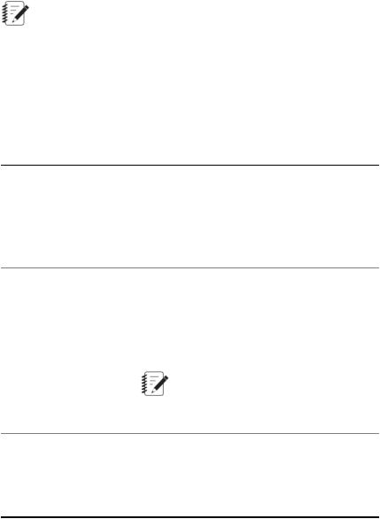
Test activity property definition
To define the properties of an activity, select the activity icon on the Procedure tab, and then click the Properties tab.You can choose to define properties as fixed values or variable values. The following example shows the property definitions for a Cycle test activity.
Multipurpose Elite Test Design Guide 19
3.0 Designing a Test
Cycle Activities Properties
Error indicators assist definition
Red error icons appear next to activity property fields where information is missing or incorrect.
20 Multipurpose Elite Test Design Guide
3.0 Designing a Test
Error Indicators
3.2.3.1.0 Deleting and Disabling Test Activities
If you want to remove a test activity from the test procedure, you can either delete the test activity or disable the test activity.
When you delete the activity, the activity is permanently removed from the test procedure. This action cannot be undone, and you will have to either recreate the test activity or revert to a previously-saved version of the test that contains the activity.
If you do not want to delete a test activity, but you also want to temporarily prevent the activity from occurring during a test run, you can disable the activity. When you disable a test activity, the test activity becomes grayed-out in the test procedure and the activity is ignored when the test is run. After you disable an activity, you can enable the activity and it will once again occur during test runs.
You may find it helpful to temporarily disable some test activities when you are creating a test or when you are troubleshooting suspected problems in the test. For example, you can disable certain portions of the test in order to focus your time on a few specific test activities that you believe are causing problems. Alternatively, if you want to remove a troublesome test activity, but you are unsure of the impacts, you can temporarily disable that test activity and replace it with a modified activity and perform a test run to view the results. If you determine that you do need the disabled test activity, you can later "retrieve" the test activity by enabling it.
To delete, disable, or enable a test activity, right-click the test activity and select Delete, Disable, or Enable (if the test activity is currently disabled).
Multipurpose Elite Test Design Guide 21

3.0Designing a Test
3.2.3.2.0Variables Overview
Typically, when you enter a value for a property in an activity, you can change the value only when the test is stopped and the test procedure is unlocked. In this sense, the property is “fixed.”
With the use of variables, you can associate a property of an activity with a variable.This allows you to change the variable value without selecting the activity.
For example, suppose you create a test procedure that includes several command activities that all use the same frequency. Rather than enter a frequency value for each activity separately, you could associate all the frequency properties with a “Frequency” variable. Then, between tests (with the test stopped and the test procedure unlocked), you could use the Variables Editor to change the frequency value of all the activities at the same time. For more information about the Variables Editor, see the Multipurpose Elite User Guide. The following example shows how to make the Frequency property of the Cycle activity a variable.
Cycle Activity New Variable
Variable use in MTS TestSuite software
MTS TestSuite software uses variables extensively throughout its applications:
22 Multipurpose Elite Test Design Guide
3.0 Designing a Test
•The MPE application uses variables to simplify test creation and modification, allow operator interaction in the test flow, and facilitate monitor display.
•The MTS TestSuite Reporter Add-In for Microsoft Excel uses variables to capture test data for test reports.
•The various MTS Analyzer applications use variables to create “what if” scenarios using specimen variables and data from test runs.
Test activities and variables
The MPE application allows you to define many of the individual properties of test activities as variables. The MPE application also includes test activities you can use to manipulate variables in the test flow, as follows:
•Assign Variables activity
•Calculate Variables activity
•Input Parameters activity
You can use these activities in a variety of ways to manipulate variables. For example, you can use an Input Parameters activity to allow the operator to change variable values while the test is running.
Adding calculations to variables
You can add mathematical operators to variables to create calculated variables.You can do this in two ways, depending on test design considerations:
•Click the Variables tab in the main window to add calculations to individual variables.
•Add the Calculate Variables activity to the test procedure. This activity allows you to add calculations to variables in the test flow.
Adding and editing variables
You can add or edit variables from within the various variable editing windows and editors (such as the Map Variables window or the Calculation Editor). You can click the Add Variable (green plus sign) or Edit Variable (...) icon or right-click and select New Variable. To edit a variable, right-click a variable name and select Edit Variable.
3.2.3.3.0 Information for an Operator
You can add information for an operator, such as hardware installation instructions or safety information, directly into your test design. This allows you to create the information visible to the operator during the test, and control at which point in the test flow to show the information.
To do this, add special test activities and run-time devices to your test.
•The Custom Message Window activity allows you to show a custom message to the operator anytime the test is running.
•The Run External Application activity allows you to show documents that require external applications to launch, such as word processing, spreadsheet, and video documents.
•The Custom Help monitor display allows you to show custom help information, such as files in the .chm file format, that you create for the test.
Multipurpose Elite Test Design Guide 23
3.0 Designing a Test
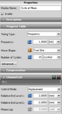
3.2.4.0 Working with Test-Run Display Devices
When you start the test, you can see real-time test information on the Test-Run Display panel.
Add monitor display devices
To add monitor display devices to your test, click the Test-Run Display tab and drag monitor display devices from the toolbox to the work area. When you do this, error icons on the device icon and Error list guide you to define required properties. The following example shows a Signal Scope device, which simulates an oscilloscope on the Test-Run Display tab when the test executes. To view its properties, you select the Signal Scope device on the work area.
Signal Scope Monitor Display
3.2.5.0 Test Execution Overview
Using Station Manager with TestSuite software
The Station Manager application runs in the background alongside the MPE application. When you design or run tests with the MPE application, minimize the Station Manager application to simplify your PC desktop.
24 Multipurpose Elite Test Design Guide

3.0 Designing a Test
Caution:
Improperly or carelessly modifying the settings in the Station Manager application can result in unexpected actuator movement.
Unexpected actuator movement can result in injury to personnel or damage to the equipment and the specimen.
Only expert-level users attempt to perform activities using the Station Manager application. Every major function that can be performed in the Station Manager application can be also performed in MPE. However, expert-level users may need to restore the Station Manager application to perform certain station activities in some exceptional scenarios.
The activities that an expert user may perform with the Station Manager application varies with your station and test setup, but typically includes:
•Install new hardware resources. This is done using the Station Builder tool in the Station Manager application.
•Adjust commands settings (such as ramp and taper times). This is done using the Channel Options tool in the Station Manager application.
•Access the values of calculation parameters and variables. This is done using the Calculation Editor in the Station Manager applicationr.
Station activities you can perform with the Multipurpose application
You can perform some station activities with the Multipurpose application, such as:
•Energize and de-energize actuator power.
•Reset and override interlocks.
•Start, hold, and stop tests.
•Install fixturing.
•Adjust inertial compensation.
•Adjust tuning.
•Install specimens.
•Set limits.
•Run function generators.
•Apply offsets.
Test execution with the MPX application
Similar to the MPE application, the MPX application can be used to run tests. However, the MPX application cannot create or modify tests. In order to create or modify tests, you must use the MPE application.
Considerations for automatic background saves
It is important to keep in mind that when you start a test run, the application automatically saves the current state of the test. If you need to modify a test without necessarily saving your changes; that is, experiment with the test, you should perform a Save As of your test, modify as required, and then run the new test.
Multipurpose Elite Test Design Guide 25

3.0 Designing a Test
If you inadvertently run a modified test and have to undo the changes you made to the test before you ran it (and the application automatically saved it), you must do so manually.
3.2.6.0Test Design Considerations
3.2.6.1.0Consider Your Station Setup
When you are designing or running a custom test, it is important to consider the following components of your station setup or you may receive unintended test results.
Polarity
When creating a custom test, the test designer can optionally configure the test to check that the polarity of the system corresponds correctly to the template using the IsSignalPolarityInverted function. This function automatically checks the polarity setting of the station and returns a True or False value. When designing a test, you can add this function as a condition to an If-Else condition activity at the beginning of a test and determine how the test should proceed based upon whether or not the polarity is inverted. In most cases, you can prompt the operator to change the polarity of the station if it is incorrect.
Most MTS-supplied tests contain this function. However, if you a running a custom test that was not supplied by MTS and you don't use this function, it is important that the test designer communicates to the operator which polarity mode (tension positive or compression positive) should be used when running the test.
Caution:
Running a test using the incorrect polarity setting can cause unintended results, which may result in unexpected actuator movement.
Unexpected actuator movement can result in injury to personnel or damage to the equipment and the specimen.
Always be aware of which polarity mode a test should be run using before running the test. If, for example, you run a test that assumes compression is positive and you set tension as positive when you install fixturing, you may receive “inverted” test results, the actuator may move in the opposite direction that was intended, or the test may not run at all.
Limits
When you design a test, it is important to be aware of the specimen and fixture limits (referred to as “station limits”) set on the station, and it is good practice to set proper limits to protect your fixturing and specimen from damage. You can configure limits in the Set Up node of the Explorer tree. If these station limits are turned on and assigned an action, they operate in tandem with the test limits you set within the test procedure. For example, if you set up a test limit for a maximum of 100 N of compressive force, and the station limit is set to only allow 80 N of compressive force, the limit will trigger when the actuator exceeds 80 N of compressive force regardless of what the test design commands. In this case, you can resolve this issue by either raising the limit on the station to 100 N or changing the test design so it only commands 80 N of compressive force.
In addition to the specimen, fixture, and test limits, there are also machine limits, such as the 5 G actuator acceleration limit. Machine limits cannot be disabled and are used to protect the machine from damage.
26 Multipurpose Elite Test Design Guide
3.0 Designing a Test
Offsets
If an offset is applied to the station, the test will respect that offset and run assuming the offset position is “zero”. For example, if the station has an offset of 2 mm axial displacement, and the test commands the actuator to ramp to zero, the actuator will ramp to 2 mm axial displacement.
Caution:
If you run a test that assumes an offset that does not exist on the station, you may receive unintended test results, which may result in unexpected actuator movement.
Unexpected actuator movement can result in injury to personnel or damage to the equipment and the specimen.
Always be aware of the offsets that are set on the station before running a test.
3.2.6.2.0 C-Stop (Controlled Stop) Interlock Action
The C-Stop Interlock is an action you can assign to specimen and fixture limit detectors during system setup.
For example, when you right-click the thumb control used to adjust limits in the Set Up node, a context menu appears with C-Stop Interlock in the Actions list, along with other options, such as Interlock, Indicate, and so on.
You can also assign the C-Stop Interlock action to limit detection activities when designing a test.
C-Stop Interlock Configuration
The C-Stop Interlock action is configured to Hold At Level in the Stable Displacement control mode with the Zero the Output option enabled.
Important:
The C-Stop Interlock action configuration is set with MTS controller software and should not be changed for typical operations. Contact MTS for information about changing the C-Stop Interlock action configuration.
C-Stop action versus Interlock action
The primary benefit of the C-Stop Interlock action is that when it is triggered, the controller performs a control mode switch to stable displacement and the actuator is held in place. The C-Stop Interlock action does not remove power from the actuator.
The C-Stop Interlock action is appropriate for instances in which limiting actuator movement after the action is triggered is the primary objective.
In contrast, when an Interlock action is triggered, the controller removes power from the actuator, which allows the actuator to continue to fall until the mechanical brake engages.This may result in actuator movement greater than 30 mm between the time the detector limit is triggered and when the mechanical brake engages.
The Interlock action is appropriate for instances in which removing actuator power, regardless of incidental actuator movement, is the primary objective.
Multipurpose Elite Test Design Guide 27

3.0 Designing a Test
Recommended:
It is important to understand how detector actions affect system operation. In most cases, MTS recommends using the C-Stop Interlock action for detectors during system setup and test design for MTS Acumen systems.
Resetting a C-Stop Interlock action
Once a C-Stop Interlock action is triggered, you must click Interlock Reset before you can switch out of stable displacement, use Manual Command controls, or resume or run a test.
3.2.6.3.0 Using Stop Actions Within a Test
When you design the test to stop programmatically, the actuator may continue to move when the stop occurs. The occurrence depends on the relationship between program command and specimen characteristics. In general, this condition is more likely to occur with higher specimen mass, higher command frequency, and higher command amplitudes.
3.2.7.0 Generating a Report in MP
To generate reports from within MP, you must have an existing report template and the Microsoft Excel application or a suitable Microsoft Excel reader. To design or modify a report template, you must have the Reporter Add-In application, which is a separately licensed product.
1.On the Explorer panel, right-click the Test Run name and select Generate Report. To generate multiple reports at one time, click Test Runs on the Explorer panel to see the Test Runs table. Select the test runs to include in the reports. To select more than one, press the Ctrl key and click the report name. Right-click and select Generate Report. The Generate Report window opens.
2.Select one or more templates to use for your reports and click Generate Report.
3.Microsoft Excel opens with the newly generated report. If multiple test runs were selected, a separate report for each Test Run will open. Modify as desired and save and close. By default, the report is shown
below the test run name in the Explorer panel. You can click Preferences > Configuration and select a different location for generated reports on the Project tab.
3.2.8.0 Generating a Report Using the Excel Reporter Add-In
Note:
To generate a report using the Excel Reporter Add-In, you must have purchased a separate license for the Reporter Add-In product. It also requires the installation of Microsoft Excel software or another suitable Microsoft Excel reader.
1.Open a report template in Excel (MTS templates are located in C:\MTS TestSuite\Report Templates).
2.Click the MTS TestSuite Report tab in the ribbon.
3.Click the Test icon in the ribbon and open the test that contains the test run that requires a report.
4.In the Generate section of the ribbon, click Source and select the test, test run, or analysis run that you want to use to create a report.
5.Click the Report icon on the ribbon.
28 Multipurpose Elite Test Design Guide
3.0 Designing a Test
6. The system will launch another instance of Microsoft Excel and show the newly generated report file.
Multipurpose Elite Test Design Guide 29
Loading...