


 Loading...
m
be certain.
318 Load Unit
Product Information
Model 318.10
Model 318.25
Model 318.50
100-183-837 B
Copyright information Trademark information
© 2007, 2009 MTS Systems Corporation. All rights reserved.
MTS is a registered trademark of MTS Systems Corporation within the United States. This trademark may be protected in other countries.
Molykote is a registered trademark of Dow Chemical Corporation. All other trademarks or service marks are property of their respective owners.
Publication information |
MANUAL PART NUMBER |
PUBLICATION DATE |
|
|
|
|
100-183-837 A |
June 2007 |
|
|
|
|
100-183-837 B |
April 2009 |
|
|
|

Contents
Technical Support |
7 |
|
|
|
||
|
How to Get Technical Support |
7 |
|
|||
|
Before You Contact MTS |
7 |
|
|
||
|
If You Contact MTS by Phone |
9 |
|
|||
|
Problem Submittal Form in MTS Manuals |
10 |
||||
Preface |
11 |
|
|
|
|
|
|
|
|
|
|
|
|
|
Before You Begin |
11 |
|
|
|
|
Conventions |
12 |
|
|
|
|
|
|
Documentation Conventions |
12 |
|
|||
Introduction 15 |
|
|
|
|
||
|
|
|
|
|
||
|
Load Unit: Overview 15 |
|
|
|
||
|
318 |
Load Unit: Component Identification |
17 |
|||
|
318 |
Load Unit: Component Description 18 |
||||
|
318 |
Load Unit: Specifications |
20 |
|
||
|
Series 661 Force Transducer: Specifications |
24 |
||||
|
318 |
Load Unit: Dimensions 26 |
|
|||
Safety |
33 |
|
|
|
|
|
|
|
|
|
|
||
|
General Safety Practices |
33 |
|
|
||
|
Safety Practices Before System Operation |
34 |
||||
|
Safety Practices While the System Is in Operation 39 |
|||||
|
Hazard Icons 41 |
|
|
|
|
|
|
318 |
Load Unit: Hazard Labels |
42 |
|
||
|
45 |
|
|
|
|
|
|
318 |
Load Unit: Crush Point Hazards 45 |
|
|||
318 Load Unit |
Contents |
3 |

Installation |
47 |
|
|
|
|
|
|
|
|
318 |
Load Unit: Unpack Upright Configuration |
47 |
|
||||||
318 |
Load Unit: Unpack Horizontal Configuration |
49 |
|
||||||
318 |
Load Unit: Connect Cables |
54 |
|
|
|
|
|
|
|
318 |
Load Unit: Connect Hydraulics |
56 |
|
|
|
|
|
||
318 |
Load Unit: Unlock the Crosshead |
56 |
|
|
|
|
|||
Operation |
59 |
|
|
|
|
|
|
|
|
|
|
|
|
|
|
|
|
||
Load Unit: Operation Preface |
59 |
|
|
|
|
|
|
||
318 |
Load Unit: Control Module |
60 |
|
|
|
|
|
|
|
318 |
Load Unit: Crush Point Hazards |
62 |
|
|
|
|
|
||
318 |
Load Unit: Specimen Installation |
62 |
|
|
|
|
|
||
318 |
Load Unit: Position the Crosshead Hydraulically 65 |
||||||||
318 |
Load Unit: Position the Crosshead Manually |
66 |
|
||||||
318 |
Load Unit: Adjust the Grips’ Clamp Rate |
|
69 |
|
|
||||
318 |
Load Unit: Adjust the Grips’ Clamp Force |
70 |
|
||||||
Maintenance 73 |
|
|
|
|
|
|
|
|
|
|
|
|
|
|
|
|
|
||
Routine Maintenance Overview Checklist |
74 |
|
|
|
|
|
|
||
318 |
Load Unit: Maintenance Intervals |
77 |
|
|
|
|
|||
318 |
Load Unit: Daily Inspections |
78 |
|
|
|
|
|
||
318 |
Load Unit: Clean the Columns 78 |
|
|
|
|
|
|||
318 |
Load Unit: Prevent Rust |
79 |
|
|
|
|
|
|
|
318 |
Load Unit: Maintain Airmount Pressures |
|
80 |
|
|
||||
318 |
Load Unit: Bleed the Hydraulic Lift Cylinders |
81 |
|
||||||
318 |
Load Unit: Adjust the Hydraulic Locks |
83 |
|
|
|||||
318 |
Load Unit: Lubricate the Crosshead Locking Bolts |
86 |
|||||||
318 |
Load Unit: Align the Force Transducer |
87 |
|
|
|||||
111 Accumulator: Maintenance Overview |
93 |
|
|
|
|||||
111 Accumulator: Check and Change Precharge Pressure |
94 |
||||||||
244 |
Actuator: Maintenance |
98 |
|
|
|
|
|
|
|
298 HSM: Maintenance 98 |
|
|
|
|
|
|
|
|
|
252 |
Servovalve: Maintenance Overview |
100 |
|
|
|
||||
252 |
Servovalve: Replace the Filter Element |
100 |
|
|
|||||
252 |
Servovalve: Adjust the Mechanical Null |
|
102 |
|
|
||||
Servohydraulic Load Frame Maintenance and Service Logs 107
4 |
Contents |
318 Load Unit |
8 Hours/Daily |
108 |
|
||
40 Hours/Weekly |
109 |
|
||
80 Hours/Biweekly |
110 |
|
||
500 |
Hours: Crosshead and Frame |
111 |
||
500 |
Hours: Actuator 112 |
|
||
500 Hours: HSM |
113 |
|
||
500 |
Hours: Hoses and Cables 114 |
|
||
500 |
Hours: Overall Complete System 115 |
|||
500 |
Hours: Grips |
116 |
|
|
1000 Hours |
117 |
|
|
|
2000 Hours: Annual Maintenance |
118 |
|||
318 Load Unit |
Contents |
5 |
6 |
Contents |
318 Load Unit |

Technical Support
How to Get Technical Support
Start with your manuals
Technical support methods
MTS web site
www.mts.com
The manuals supplied by MTS provide most of the information you need to use and maintain your equipment. If your equipment includes MTS software, look for online help and README files that contain additional product information.
If you cannot find answers to your technical questions from these sources, you can use the internet, e-mail, telephone, or fax to contact MTS for assistance.
MTS provides a full range of support services after your system is installed. If you have any questions about a system or product, contact MTS in one of the following ways.
The MTS web site gives you access to our technical support staff by means of a Technical Support link:
www.mts.com > Contact MTS > Service & Technical Support
Telephone
Fax
Technical support outside the U.S.
techsupport@mts.com
MTS Call Center 800-328-2255
Weekdays 7:00 A.M. to 5:00 P.M., Central Time
952-937-4515
Please include “Technical Support” in the subject line.
For technical support outside the United States, contact your local sales and service office. For a list of worldwide sales and service locations and contact information, use the Global MTS link at the MTS web site:
www.mts.com > Global MTS > (choose your region in the right-hand column) > (choose the location closest to you)
Before You Contact MTS
Know your site number and system number
MTS can help you more efficiently if you have the following information available when you contact us for support.
The site number contains your company number and identifies your equipment type (material testing, simulation, and so forth). The number is usually written on a label on your MTS equipment before the system leaves MTS. If you do not have or do not know your MTS site number, contact your MTS sales engineer.
Example site number: 571167
When you have more than one MTS system, the system job number identifies which system you are calling about. You can find your job number in the papers sent to you when you ordered your system.
Example system number: US1.42460
318 Load Unit |
Technical Support |
7 |
Know information from prior technical assistance
Identify the problem
Know relevant computer information
Know relevant software information
If you have contacted MTS about this problem before, we can recall your file. You will need to tell us the:
•MTS notification number
•Name of the person who helped you
Describe the problem you are experiencing and know the answers to the following questions:
•How long and how often has the problem been occurring?
•Can you reproduce the problem?
•Were any hardware or software changes made to the system before the problem started?
•What are the model numbers of the suspect equipment?
•What model controller are you using (if applicable)?
•What test configuration are you using?
If you are experiencing a computer problem, have the following information available:
•Manufacturer’s name and model number
•Operating software type and service patch information
•Amount of system memory
•Amount of free space on the hard drive in which the application resides
•Current status of hard-drive fragmentation
•Connection status to a corporate network
For software application problems, have the following information available:
•The software application’s name, version number, build number, and if available, software patch number. This information is displayed briefly when you launch the application, and can typically be found in the “About” selection in the “Help” menu.
•It is also helpful if the names of other non-MTS applications that are running on your computer, such as anti-virus software, screen savers, keyboard enhancers, print spoolers, and so forth are known and available.
8 |
Technical Support |
318 Load Unit |
If You Contact MTS by Phone
Identify system type
Be prepared to troubleshoot
Write down relevant information
After you call
Your call will be registered by a Call Center agent if you are calling within the United States or Canada. Before connecting you with a technical support specialist, the agent will ask you for your site number, name, company, company address, and the phone number where you can normally be reached.
If you are calling about an issue that has already been assigned a notification number, please provide that number. You will be assigned a unique notification number about any new issue.
To assist the Call Center agent with connecting you to the most qualified technical support specialist available, identify your system as one of the following types:
•Electromechanical materials test system
•Hydromechanical materials test system
•Vehicle test system
•Vehicle component test system
•Aero test system
Prepare yourself for troubleshooting while on the phone:
•Call from a telephone when you are close to the system so that you can try implementing suggestions made over the phone.
•Have the original operating and application software media available.
•If you are not familiar with all aspects of the equipment operation, have an experienced user nearby to assist you.
Prepare yourself in case we need to call you back:
•Remember to ask for the notification number.
•Record the name of the person who helped you.
•Write down any specific instructions to be followed, such as data recording or performance monitoring.
MTS logs and tracks all calls to ensure that you receive assistance and that action is taken regarding your problem or request. If you have questions about the status of your problem or have additional information to report, please contact MTS again and provide your original notification number.
318 Load Unit |
Technical Support |
9 |
Problem Submittal Form in MTS Manuals
Use the Problem Submittal Form to communicate problems you are experiencing with your MTS software, hardware, manuals, or service which have not been resolved to your satisfaction through the technical support process. This form includes check boxes that allow you to indicate the urgency of your problem and your expectation of an acceptable response time. We guarantee a timely response—your feedback is important to us.
The Problem Submittal Form can be accessed:
•In the back of many MTS manuals (postage paid form to be mailed to MTS)
•www.mts.com > Contact Us > Problem Submittal Form (electronic form to be e-mailed to MTS)
10 |
Technical Support |
318 Load Unit |
Preface
Before You Begin
Safety first!
Other MTS manuals
Before you attempt to use your MTS product or system, read and understand the Safety manual and any other safety information provided with your system. Improper installation, operation, or maintenance of MTS equipment in your test facility can result in hazardous conditions that can cause severe personal injury or death and damage to your equipment and specimen. Again, read and understand the safety information provided with your system before you continue. It is very important that you remain aware of hazards that apply to your system.
In addition to this manual, you may receive additional MTS manuals in paper or electronic form.
If you have purchased a test system, it may include an MTS System Documentation CD. This CD contains an electronic copy of the MTS manuals that pertain to your test system, including hydraulic and mechanical component manuals, assembly drawings and parts lists, and operation and preventive maintenance manuals. Controller and application software manuals are typically included on the software CD distribution disc(s).
318 Load Unit |
Preface |
11 |

Conventions
Conventions
Documentation Conventions
The following paragraphs describe some of the conventions that are used in your
MTS manuals.
Hazard conventions As necessary, hazard notices may be embedded in this manual. These notices contain safety information that is specific to the task to be performed. Hazard notices immediately precede the step or procedure that may lead to an associated hazard. Read all hazard notices carefully and follow the directions that are given. Three different levels of hazard notices may appear in your manuals. Following are examples of all three levels.
Note For general safety information, see the safety information provided with your system.

 DANGER
Danger notices indicate the presence of a hazard with a high level of risk which, if ignored, will result in death, severe personal injury, or substantial property damage.

 WARNING
Warning notices indicate the presence of a hazard with a medium level of risk which, if ignored, can result in death, severe personal injury, or substantial property damage.

 CAUTION
Notes
Special terms
Illustrations
Electronic manual conventions
Caution notices indicate the presence of a hazard with a low level of risk which, if ignored, could cause moderate or minor personal injury, equipment damage, or endanger test integrity.
Notes provide additional information about operating your system or highlight easily overlooked items. For example:
Note Resources that are put back on the hardware lists show up at the end of the list.
The first occurrence of special terms is shown in italics.
Illustrations appear in this manual to clarify text. It is important for you to be aware that these illustrations are examples only and do not necessarily represent your actual system configuration, test application, or software.
This manual is available as an electronic document in the Portable Document File (PDF) format. It can be viewed on any computer that has Adobe Acrobat Reader installed.
12 Preface |
318 Load Unit |
Conventions
Hypertext links The electronic document has many hypertext links displayed in a blue font. All blue words in the body text, along with all contents entries and index page numbers, are hypertext links. When you click a hypertext link, the application jumps to the corresponding topic.
318 Load Unit |
Preface 13 |
Conventions
14 Preface |
318 Load Unit |

Introduction
Load Unit: Overview
The Load Unit is the primary structure for most materials testing. It is a standalone testing unit. The load unit consists of the load frame plus additional parts, such as hydraulic crosshead lifts and control modules. Load units come in different sizes and shapes. The following illustration shows typical load units with common accessories.
The Load Units are designed for testing materials. They can perform tension and compression tests, fatigue and fracture mechanics tests, as well as other tests. MTS manufactures a variety of grips, mounting fixtures, test area guards, and environmental chambers that can be used with the load unit.
Typical Load Units
Model 318 |
Model 322 |
Model 359 |
318 Load Unit |
Introduction |
15 |
What you need to know
MTS Systems Corporation assumes that you know how to use your controller. See the appropriate manual for information about performing any controllerrelated step in this manual’s procedures. You are expected to know how to perform the following procedures:
•Turn hydraulic pressure on and off
•Select a control mode
•Adjust the actuator position
•Zero a sensor signal
•Zero a sensor output
•Use your grips and fixtures
•Define a simple test
•Run a test
16 |
Introduction |
318 Load Unit |

318 Load Unit: Component Identification
12
2
1 |
11 |
|
3 |
|
10 |
|
9 |
|
4 |
|
5 |
8 |
7 |
|
6 |
|
|
Component Descriptions |
ITEM |
COMPONENT |
DESCRIPTION |
|
|
|
1 |
Crosshead |
Moves the up and down the column to accommodate different sized |
|
|
specimens and fixtures. The crosshead is stiff and light weight; it is one end of |
|
|
the force train. |
2Crosshead locks Clamps the crosshead to the columns. The locks are hydraulically powered.
3Crosshead lifts Raises and lowers the crosshead hydraulically to accommodate different
specimen sizes. The lifts are small hydraulic actuators.
318 Load Unit |
Introduction |
17 |

|
|
Component Descriptions |
ITEM |
COMPONENT |
DESCRIPTION |
4 |
Control panel |
Grip controls
Crosshea d lift control
Emergenc
y Stop
The Emergency Stop button is standard; the other controls are optional.
Clamps and unclamps the hydraulically controlled grips during specimen installation and removal.
Controls the crosshead lifts to raise and lower the crosshead hydraulically.
Removes hydraulic pressure from the load unit and issues an interlock signal to the controller to stop the test program.
5 |
Servovalve |
Controls both the flow rate and the direction of fluid entering the actuators. It |
|
|
determines how fast the actuator extends or retracts. |
|
|
|
6 |
Isolation pads |
Dampens the natural frequency to about 20 Hz. Optional air inflated isolators |
|
|
dampen the frequency to about 2 Hz. |
|
|
|
7 |
Accumulators |
Stores hydraulic fluid under pressure to increase the actuator’s response time. |
|
|
One accumulator connects to the pressure line; the other to the return line. |
|
|
|
8 |
LVDT |
Measures the displacement of the actuator’s travel. The linear variable |
|
|
displacement transducer (LVDT) is located inside the actuator. |
|
|
|
9 |
Manifold |
Serves as the junction point between the hydraulic power unit (HPU), |
|
|
accumulators, servovalve, and actuator. The actuator manifold controls the |
|
|
hydraulic circuit that connects the hydraulic components. |
|
|
|
10 |
Linear actuator |
Applies axial forces to specimens. The actuator is a hydraulically powered |
|
|
device that provides linear displacement of (or forces into) a specimen. Grips |
|
|
and fixtures can be mounted to the actuator. |
|
|
|
11 |
Force transducer |
Measures the axial forces applied to specimen. |
|
|
|
12 |
Lifting rings |
Allows the load unit to be moved by lifting the entire load unit. |
|
|
|
318 Load Unit: Component Description
The load unit is a stand alone testing structure. It consists of the following components:
•Load frame
•Crosshead lifts and locks
•Manifold
–Actuators
–Servovalves
–Accumulators
•Transducers
•Grip controls
18 |
Introduction |
318 Load Unit |
Load frame
Crosshead lifts and locks
Actuator manifold
Actuators
Servovalves
Accumulators
Pressure control
Transducers
Force
The load frame is the basic structure which provides the reaction mass for the force train. The base of the load frame is one end of the reaction mass and the crosshead is the other end of the reaction mass. Installing a specimen and other fixtures or components between the load unit base and the crosshead create a force train.
The load frame and the other hydraulic components mounted to it collectively create the load unit. The base houses the actuators, servovalves, and hydraulic manifold. The crosshead is mounted above the base by two columns. A control panel lets you operate the crosshead lifts, locks, and grips to assist in specimen installation procedures.
The crosshead can be positioned anywhere along the load frame columns. It is moved along the column with hydraulic lifts. When the crosshead is in an appropriate test position, it is hydraulically clamped to that position. This lets you change the load unit to test specimens of different lengths.
The Series 298 Actuator Manifold (also called a hydraulic service manifold or HSM) acts as the hydraulic interface between the HPU and the components mounted to the manifold (actuator, servovalves, and accumulators) of the load unit. It contains the required hydraulic porting and plumbing to accommodate the hydraulic components. The manifold can also control the hydraulic pressure to the load unit.
The Series 244 Actuators can be located in the middle of the load unit base or crosshead. It is a hydraulically powered piston that applies displacement of (or force into) a specimen. It can apply equal power in tension and compression. One end of the test specimen is installed into a fixture which is mounted to the end of the actuator rod.
The Series 252 Servovalves regulates the direction and flow of the hydraulic fluid to and from a hydraulic actuator. The servovalve responds to the polarity and magnitude of the command signal generated by the controller.
The Series 111 Accumulators suppress line-pressure fluctuations. The load unit includes a pressure-line accumulator to provide fluid storage so a constant line pressure can be maintained at the servovalves for maximum performance. The return-line accumulator minimizes return-line pressure fluctuations.
The load unit can be configured for several pressure configurations. The free low configuration passes the hydraulic pressure from the HPU (or hydraulic service manifold) through the manifold to the hydraulic components. The hydraulic pressure options include on/off control, high/low/off control, and high/low/off control with a proportional valve to ramp the pressure transitions.
The load unit includes a force transducer and an LVDT.
The force transducer (also called load cell or force sensor) measures the amount of tension or compression and rotational torque applied to it. It has four strain gages that form a balanced Wheatstone bridge. When forces are applied to the bridge, it becomes unbalanced and produces an electrical signal that is proportional to the force applied to it. The force transducer is a resistive device and requires a DC conditioner to process the axial signal from the Wheatstone bridge.
318 Load Unit |
Introduction |
19 |

LVDT
Grip Controls
The LVDT measures the linear actuator’s travel. The LVDT consists of a transformer with one primary and two secondary coils wound on a common cylinder. The coil is stationary inside the actuator. A core is attached to the piston rod of the actuator. As it moves inside the coil, it produces an electrical signal that represents the position of the piston rod. The phase of the signal indicates the direction the actuator rod is moving. An LVDT requires an AC conditioner to process the signal.
The grip controls provide independent clamping control of the upper and lower grips. The maximum pressure for the grip controls can be set up to 69 MPa (10,000 psi). The pressure is factory set to 20 MPa (3000 psi); 45 MPa (6500 psi); or 69 MPa (10,000 psi) to accommodate a variety of grips manufactured by MTS Systems Corporation. A front panel control allows the grip pressure to be adjusted within the factory setting. A rate control sets how fast the grips open and close.
318 Load Unit: Specifications
This section provides the specifications of the Series 318 Load Unit.
General specifications The following table lists general specifications for the Series 318 Load Unit:
PARAMETER |
SPECIFICATION |
|
|
Load frame |
|
Lifts |
Hydraulic (optional) |
Locks |
Hydraulic (optional) |
Grip control |
Hydraulic (optional) |
|
|
Service manifold |
Series 298 Actuator Manifold |
Maximum flow |
114 L/min (30 gpm) |
|
|
Axial actuator |
Series 244 Actuator |
Displacements |
100 mm (4 in) |
|
150 mm (6 in) |
|
250 mm (10 in) |
|
|
Accumulator |
Series 111 Accumulator |
|
|
20 |
Introduction |
318 Load Unit |
PARAMETER |
SPECIFICATION |
|
|
Weight* |
approximate minimum weight |
Base mount |
|
318.10500 kg (1100 lb)
318.25960 kg (2120 lb)
318.501900 kg (4200 lb)
Crosshead mount
318.10555 kg (1225 lb)
318.251065 kg (2345 lb)
318.502100 kg (4625 lb)
*The weight specification is for lifting and moving purposes. The weight of accessories and special fixtures must be added. The actual shipping weight must be determined by a scale.
Force Ratings The Series 318 Load Units include other products. The following table lists specifications from several product information manuals. Specifications listed in the respective product information manual supersede the following specifications.
MODEL |
FRAME |
ACTUATOR |
TRANSDUCER |
MOUNTING |
|
FATIGUE RATING |
RATING* |
RATING |
THREADS |
318.10 |
100 kN |
25 kN |
25 kN |
M27 x 2 |
|
(22 kip) |
(5.5 kip) |
(5.5 kip) |
(1 - 14 UNS) |
|
|
|
|
|
|
|
50 kN |
50 kN |
M27 x 2 |
|
|
(11 kip) |
(11 kip) |
(1 - 14 UNS) |
|
|
|
|
|
|
|
100 kN |
100 kN |
M27 x 2 |
|
|
(22 kip) |
(22 kip) |
(1 - 14 UNS) |
|
|
|
|
|
318.25 |
250 kN |
100 kN |
100 kN |
M27 x 2 |
|
(55 kip) |
(22 kip) |
(22 kip) |
(1 - 14 UNS) |
|
|
|
|
|
|
|
250 kN |
250 kN |
M36 x 2 |
|
|
(55 kip) |
(55 kip) |
(1 1/2 - 12 UNF) |
|
|
|
|
|
318.50 |
500 kN |
250 kN |
250 kN |
M36 x 2 |
|
(110 kip) |
(55 kip) |
(55 kip) |
(1 1/2 - 12 UNF) |
|
|
|
|
|
|
|
500 kN |
500 kN |
M52 x 2 |
|
|
(110 kip) |
(110 kip) |
(2 -12 UNF) |
*At 21 MPa (3000 psi)
Stiffness Data Stiffness is a way to measure the deflection of the force train. Deflection rates can vary 20%, depending on the actuator and force transducer you use.
318 Load Unit |
Introduction |
21 |

For the most accurate high frequency test results, use a load unit with a fatigue rating that is larger than its actuator’s force rating.
C
D
B
A
For example, a Model 318.25 Load Unit with a 55 kip fatigue rating and a 22 kip actuator will have smaller deflections than a Model 318.10 Load Unit with a 22 kip fatigue rating and a 22 kip actuator.
Spring rates are determined at each load unit’s full fatigue rating with its crosshead raised 1270 mm (50 in.) above the baseplate.
The Stiffness Graph shows how stiffness is affected when the height of the crosshead is changed.
DEFLECTIONS |
MODEL 318.10 |
MODEL 318.25 |
MODEL 318.50 |
|||
|
100 KN/22 KIP |
|
250 KN/55 KIP |
|
500 KN/110 KIP |
|
|
|
|
|
|
|
|
A - B base |
0.15 mm |
0.006 in |
0.18 mm |
0.007 in |
0.20 mm |
0.008 in |
|
|
|
|
|
|
|
B - C columns |
0.10 mm |
0.004 in |
0.15 mm |
0.006 in |
0.18 mm |
0.007 in |
|
|
|
|
|
|
|
C - D crosshead |
0.13 mm |
0.005 in |
0.25 mm |
0.010 in |
0.28 mm |
0.011 in |
|
|
|
|
|
|
|
22 |
Introduction |
318 Load Unit |

DEFLECTIONS
A - D overall frame
Spring rates
10
|
20 |
|
(kips) |
10 |
|
Limits |
5 |
|
Side Load |
||
2 |
||
Maximum |
1 |
|
|
||
|
0.5 |
5
|
|
MODEL 318.10 |
MODEL 318.25 |
MODEL 318.50 |
|
||||||||||||||
|
|
100 KN/22 KIP |
250 KN/55 KIP |
500 KN/110 KIP |
|
||||||||||||||
|
|
0.38 mm |
0.015 in |
0.58 mm 0.023 in |
0.66 mm 0.026 in |
||||||||||||||
|
|
2.6 x 10⁸ N/m |
4.3 x 10⁸ N/m |
7.5 x 10⁸ N/m |
|
||||||||||||||
|
|
(1.5 x 10⁶ lb/in) |
(2.4 x 10⁶ lb/in) |
(4.3 x 10⁶ ib/in) |
|||||||||||||||
|
|
Free Column Length (cm) |
|
|
|
|
|
|
|
||||||||||
25 |
|
|
50 |
125 |
|
250 |
|
||||||||||||
|
|
|
|
|
|
|
|
|
|
|
|
|
|
|
|
|
|
80 |
Maximum |
|
|
|
|
|
|
|
|
|
|
|
|
|
|
|
|||||
|
|
|
|
|
|
|
|
|
|
|
|
|
|
|
|
|
|
45 |
|
|
|
|
|
|
|
|
|
|
|
|
|
|
|
|
|
|
|
|
|
|
|
|
|
|
|
|
|
|
|
|
|
|
|
|
|
|
|
22 |
Side |
|
|
|
|
|
|
|
|
|
|
|
|
|
|
|
|
|
|
|
|
|
|
|
|
|
|
|
|
|
|
|
318.50 |
|
|
|
|
|
|
||
|
|
|
|
|
|
|
|
|
|
|
|
|
|
|
|
|
Load |
||
|
|
|
|
|
|
|
|
|
|
|
|
|
|
|
|
|
|
|
|
|
|
318.10 |
|
|
|
|
318.25 |
|
|
|
|
|
|
|
|
|
9 |
|
|
|
|
|
|
|
|
|
|
|
|
|
|
|
|
|
|
|
|
Limits |
|
|
|
|
|
|
|
|
|
|
|
|
|
|
|
|
|
|
|
4.5 |
|
|
|
|
|
|
|
|
|
|
|
|
|
|
|
|
|
|
|
(kN) |
|
|
|
|
|
|
|
|
|
|
|
|
|
|
|
|
|
|
|
|
|
|
|
|
|
|
|
|
|
|
|
|
|
|
|
|
|
|
|
2 |
|
|
|
|
|
|
|
|
|
|
|
|
|
|
|
|
|
||||
10 |
|
|
20 |
50 |
|
100 |
|
||||||||||||
|
|
Free Column Length (in) |
|
|
|
|
|
|
|
||||||||||
Stiffness Graph
318 Load Unit |
Introduction |
23 |

Series 661 Force Transducer: Specifications
The force transducer used with this system is a Series 661 Force Transducer. The following are the specifications for the force transducers.
|
|
PARAMETER |
|
SPECIFICATION |
|
|
|
|
|
|
|
|
|
|
|
Maximum excitation voltage |
15 V DC |
|
|
|
|
|
|
|
|
|
|
|
|
Bridge resistance |
350 ¾ |
|
|
|
|
|
|
|
|
||
|
|
Maximum crosstalk |
1.0% of full scale torsional to load |
|
||
|
|
|
|
|
|
|
|
|
Hysteresis |
|
0.08% of full scale (250 N–2.5 kN) |
|
|
|
|
|
|
0.05% of full scale (5 kN–50 kN) |
|
|
|
|
|
|
0.15% of full scale (100 kN–500 kN) |
|
|
|
|
|
|
0.20% of full scale (1000 kN) |
|
|
|
|
|
|
|
|
|
|
|
Nonlinearity |
|
0.08% of full scale |
|
|
|
|
|
|
0.15% of full scale for Models 661.22/.23/.31 |
|
|
|
|
|
|
|
|
|
|
|
Temperature |
|
0.004% of reading/°C (0.002%/°F) |
|
|
|
|
Usable range |
-54°C (-65°F) to +121°C (+250°F) |
|
||
|
|
Compensated range |
+21°C (+70°F) to +77°C (+170°F) |
|
||
|
|
Sensitivity |
0.0036% of full scale/°C |
|
||
|
|
|
|
(0.0020% of full scale/°F) |
|
|
|
|
|
|
|
|
|
|
|
Output |
|
2 mV/V at full-scale load |
|
|
|
|
|
|
|
|
|
|
|
Connector |
|
PT02ER-10-6P |
|
|
|
|
|
|
|
|
|
|
|
|
|
|
|
|
MODEL |
LOAD CAPACITY |
THREAD SIZE* |
|
WEIGHT |
|
|
661.11-01 |
250 N |
M6 x 1.0 mm x 6.3 mm |
0.45 kg |
|
||
|
(50 lbf) |
(1/4 - 28 UNF x 0.25 in |
(1 lb) |
|
||
|
|
|
|
|
||
661.11-02 |
500 N |
M6 x 1.0 mm x 6.3 mm |
0.45 kg |
|
||
|
(100 lbf) |
(1/4 - 28 UNF x 0.5 in |
(1 lb) |
|
||
|
|
|
|
|
||
661.18-01 |
1 kN |
M12 x 1.25 mm x 25.4 mm |
2.27 kg |
|
||
|
(220 lbf) |
(1/2 - 20 UNF x 1.0 in) |
(5 lb) |
|
||
|
|
|
|
|
||
661.18-02 |
2.5 kN |
M12 x 1.25 mm x 25.4 mm |
2.27 kg |
|
||
|
(550 lbf) |
(1/2 - 20 UNF x 1.0 in) |
(5 lb) |
|
||
|
|
|
|
|
||
661.19-01 |
5 kN |
M12 x 1.25 mm x 25.4 mm |
3.07 kg |
|
||
|
(550 lbf) |
(1/2 - 20 UNF x 1.0 in) |
(6.75 lb) |
|
||
|
|
|
|
|
||
661.19-02 |
10 kN |
M12 x 1.25 mm x 25.4 mm |
3.07 kg |
|
||
|
(2.2 kip) |
(1/2 - 20 UNF x 1.0 in) |
(6.75 lb) |
|
||
|
|
|
|
|
||
661.19-03 |
15 kN |
M12 x 1.25 mm x 25.4 mm |
3.07 kg |
|
||
|
(3.3 kip) |
(1/2 - 20 UNF x 1.0 in) |
(6.75 lb) |
|
||
|
|
|
|
|
||
661.19-04 |
25 kN |
M12 x 1.25 mm x 25.4 mm |
3.07 kg |
|
||
|
(5.5 kip) |
(1/2 - 20 UNF x 1.0 in) |
(6.75 lb) |
|
||
|
|
|
|
|
|
|
24 |
Introduction |
318 Load Unit |

MODEL |
LOAD CAPACITY |
THREAD SIZE* |
WEIGHT |
661.20-01 |
25 kN |
M27 x 2.0 mm x 31.7 mm |
9.75 kg |
|
(5.5 kip) |
(1 - 14 UNS-3B x 1.25 in) |
(21.5 lb) |
|
|
|
|
661.20-02 |
50 kN |
M27 x 2.0 mm x 31.7 mm |
9.75 kg |
|
(11 kip) |
(1 - 14 UNS-3B x 1.25 in) |
(21.5 lb) |
|
|
|
|
661.20-03 |
100 kN |
M27 x 2.0 mm x 31.7 mm |
9.75 kg |
|
(2.2 kip) |
(1 - 14 UNS-3B x 1.25 in) |
(21.5 lb) |
|
|
|
|
661.22-01 |
250 kN |
M36 x 2.0 mm |
13.2 kg |
|
(3.3 kip) |
(1 1/2 - 12 UNC-2B) |
(29 lb) |
|
|
|
|
661.23-01 |
500 kN |
M52 x 2.0 mm x 48.3 mm |
16 kg |
|
(5.5 kip) |
(2.0 - 12 UN-2B x 1.9 in) |
(35.3 lb) |
|
|
|
|
661.31-01 |
1000 kN |
M76 x 1.75 mm x 28.4 mm |
49.9 kg |
|
(220 kip) |
(2.0 - 12 UN-2B x 1.35 in) |
(110 lb) |
*The thread sizes are available with either coarse or fine threads.
Dimensions The following dimensions are rounded off to the nearest millimeter or eight-inch.
|
|
|
C |
A |
|
||
|
E
D
 B
B 

MODEL |
A |
B* |
C |
D* |
E |
661.11-01 |
70 mm |
18 mm |
7 mm |
38 mm |
61 mm |
|
(2–3/4 in) |
(3/4 in) |
(1/4 in) |
(1–1/5 in) |
(2–3/8 in |
|
|
|
|
|
|
661.18-01 |
105 mm |
32 mm |
7 mm |
67 mm |
64 mm |
|
(4–1/4 in) |
(1–1/4 in) |
(1/4 in) |
(2–5/8 in) |
(2–1/5 in) |
|
|
|
|
|
|
661.19-01 |
105 mm |
32 mm |
7 mm |
67 mm |
64 mm |
|
(4–1/4 in) |
(1–1/4 in) |
(1/4 in) |
(2-5/8 in) |
(2–1/5 in) |
|
|
|
|
|
|
661.20-01 |
154 mm |
57 mm |
10 mm |
95 mm |
89 mm |
|
(6 in) |
(2–1/4 in) |
(3/8 in) |
(3–3/4n) |
(3–1/2 in) |
|
|
|
|
|
|
661.22-01 |
114 mm |
92 mm |
1 mm |
203 mm |
74 mm |
|
(4–1/2 in) |
(3–5/8 in) |
(>1/4 in) |
(8 in) |
(2–7/8 in) |
|
|
|
|
|
|
661.23-01 |
152 mm |
140 mm |
N/A |
203 mm |
86 mm |
|
(6 in) |
(5–1/5 in) |
|
(8 in) |
(3–3/8 in) |
|
|
|
|
|
|
661.31-01 |
222 mm |
203 mm |
N/A |
305 mm |
124 mm |
|
(8–3/4 in) |
(8 in) |
|
(12 in) |
(4–7/8 in) |
*This dimension applies to both ends
318 Load Unit |
Introduction |
25 |

Introduction 26
Dimensions Unit Load 10B.318
Standard column lengths indicated
Note: Dimensions are inches (mm)
Weight: 1100 lbs (500 kg) is normal maximum weight. Accessories and special fixtures must be added. This weight specification
is for lifting and moving purposes. Actual shipping weight must be determined by scale.
Dimensions Unit: Load 318
Unit Load 318

lengths indicated |
inches (mm) |
Standard column |
Note: Dimensions are |
318.25B Load Unit Dimensions
318 Load Unit |
Introduction |
27 |
Introduction 28
Standard column lengths
Note: Dimensions are
(mm
Weight: 4200 lbs (1900 kg) is normal maximum weight. Accessories and special

 fixtures must be added. This weight
  specification is for lifting and moving


 purposes. Actual shipping weight
Dimensions Unit Load 50B.318
Unit Load 318

Unit Load 318
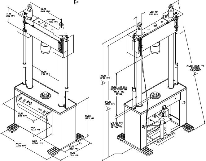
Dimensions Actuator Crosshead with Unit Load 10B.318
Introduction
Standard column lengths
Standard 6" (152.5 mm) actuator stroke indicated
Note: Dimensions are
(mm
Weight: 1100 lbs (500 kg) is normal maximum
weight. Accessories and special fixtures must be added. This weight specification is for lifting and moving purposes.
Actual shipping weight must be
29

Introduction 30
Dimensions Actuator Crosshead with Unit Load 25B.318
Standard column lengths indicated
Standard 6" (152.5 mm) actuator stroke indicated
Note: Dimensions are inches (mm)
Weight: 2120 lbs (960 kg) is normal maximum weight. Accessories and special fixtures
must be added. This weight specification is for lifting and moving purposes.
Actual shipping weight must be determined by scale.
Unit Load 318
Loading...