


 Loading...
be certain.
MTS Series 793 Tuning and Calibration
100-147-134 E
Copyright information
Trademark information
Proprietary information
Software validation and verification
© 2006–2009 MTS Systems Corporation. All rights reserved.
MTS, FlexTest, Temposonics, and TestWare are registered trademarks of MTS Systems Corporation; MPT, Station Builder, Station Manager, and TestStar are trademarks of MTS Systems Corporation within the United States. These trademarks may be protected in other countries.
Microsoft and Windows are registered trademarks of Microsoft Corporation. All other trademarks or service marks are property of their respective owners.
Software use and license is governed by MTS’s End User License Agreement which defines all rights retained by MTS and granted to the End User. All Software is proprietary, confidential, and owned by MTS Systems Corporation and cannot be copied, reproduced, disassembled, decompiled, reverse engineered, or distributed without express written consent of MTS.
MTS software is developed using established quality practices in accordance with the requirements detailed in the ISO 9001 standards. Because MTSauthored software is delivered in binary format, it is not user accessible. This software will not change over time. Many releases are written to be backwards compatible, creating another form of verification.
The status and validity of MTS’s operating software is also checked during system verification and routine calibration of MTS hardware. These controlled calibration processes compare the final test results after statistical analysis against the predicted response of the calibration standards. With these established methods, MTS assures its customers that MTS products meet MTS’s exacting quality standards when initially installed and will continue to perform as intended over time.
Publication information |
MANUAL PART NUMBER |
PUBLICATION DATE |
MTS 793 SOFTWARE RELEASE |
|
|
|
|
|
100-147-134 A |
June 2006 |
Version 4.0A or later |
|
|
|
|
|
100-147-134 B |
October 2006 |
Version 4.0B or later |
|
|
|
|
|
100-147-134 C |
January 2008 |
Version 5.0B or later |
|
|
|
|
|
100-147-134 D |
September 2008 |
Version 5.1A or later |
|
|
|
|
|
100-147-134 E |
August 2009 |
Version 5.2A or later |
|
|
|
|
2 |
MTS Series 793 Tuning and Calibration |

Contents
Technical Support |
7 |
|
|
|
|
|
|
|
|||||
How to Get Technical Support |
7 |
|||||
Before You Contact MTS |
8 |
|
|
|||
If You Contact MTS by Phone |
9 |
|||||
Problem Submittal Form in MTS Manuals 11 |
||||||
Preface 13 |
|
|
|
|
|
|
|
|
|
|
|
|
|
Before You Begin |
13 |
|
|
|
|
|
Conventions |
14 |
|
|
|
|
|
Documentation Conventions |
14 |
|||||
Chapter 1 |
Introduction |
17 |
||||
|
|
|
|
|
|
|
About Tuning |
19 |
|
|
|
|
|
How the Tuning Controls Work |
20 |
|
||||
Proportional (P) Gain |
23 |
|
|
|
||
Integral (I) Gain |
25 |
|
|
|
|
|
Derivative (D) Gain 26 |
|
|
|
|||
Feed Forward (F or F2) Gain |
29 |
|||||
Stabilization Gain (S Gain) |
30 |
|
||||
Delta P Stabilization |
31 |
|
|
|
||
Acceleration Stabilization |
32 |
|
||||
Forward Loop Filter (FL Filter) |
32 |
|||||
Tuning Characteristics of Control Modes 33 |
||||||
Creating a Tuning Program |
35 |
|
|
|||
About Auto Tuning 38 |
|
|
|
|
||
Other Tuning Considerations |
40 |
|
|
|||
Monitoring Waveforms While Tuning 42
MTS Series 793 Tuning and Calibration |
Contents |
3 |

About Calibration 44
System Calibration 44
Sensor Calibration 45
Chapter 2 |
Tuning Procedures |
47 |
|
||||
|
|
|
|
|
|
|
|
When to Tune 49 |
|
|
|
|
|
|
|
Tuning for the First Time 52 |
|
|
|
|
|
|
|
How To Warm Up Station Hydraulics |
53 |
|
|
|
|||
How to Set Servovalve Polarity |
56 |
|
|
|
|
|
|
How to Balance the Servovalve |
60 |
|
|
|
|
|
|
How to Balance Dual Valves |
63 |
|
|
|
|||
How to Adjust Dither |
67 |
|
|
|
|
|
|
How to Manually Tune the Control Loop |
70 |
|
|
|
|||
Tuning the Displacement Control Mode |
71 |
|
|
||||
Tuning the Force Control Mode |
76 |
|
|
|
|
||
Tuning the Strain Control Mode |
82 |
|
|
|
|
||
How to Perform Advanced Tuning Techniques 88 |
|
|
|||||
How to Auto-Tune 88 |
|
|
|
|
|
||
How to Manually Tune Three-Stage Servovalves |
93 |
||||||
Zero the Spool Position Signal |
99 |
|
|
|
|||
How to Monitor Inner Loop Signals |
100 |
|
|
||||
How to Use Error to Tune I Gain |
102 |
|
|
||||
About the Cascaded PIDF Control Mode |
104 |
|
|||||
How to Tune a Cascaded PIDF Control Mode 104 |
|||||||
About Channel Limited Channel (CLC) Control Modes 106 |
|||||||
How to Tune a CLC Control Mode |
107 |
|
|
||||
About Dual Compensation Control Modes |
110 |
|
|||||
How to Tune a Dual Compensation Control Mode |
112 |
||||||
About Tuning Filters |
115 |
|
|
|
|
|
|
How to Enable a Tuning Filter |
119 |
|
|
|
|||
4 |
Contents |
MTS Series 793 Tuning and Calibration |

Chapter 3 |
Calibration Procedures |
121 |
||||
|
|
|
|
|
||
Pre-Calibration Considerations |
123 |
|
|
|
||
About TEDS Sensors |
125 |
|
|
|
||
Shunt Calibration |
126 |
|
|
|
|
|
Displacement Sensor Calibration |
130 |
|
|
|
||
Displacement Sensor Calibration: Abbreviated Procedure |
132 |
|||||
Displacement Sensor Calibration: Detailed Procedure 133 |
||||||
Force Sensor Calibration |
156 |
|
|
|
|
|
Force Sensor Calibration: Abbreviated Procedure |
158 |
|
||||
Force Sensor Calibration: Detailed Procedure |
159 |
|
|
|||
How to Install a Shunt-Calibration Resistor on an I/O Carrier Board 188 |
||||||
Encoder and Temposonics Calibration 189 |
|
|
|
|||
Encoder Calibration: Abbreviated Procedure |
190 |
|
|
|||
Encoder Calibration: Detailed Procedure 191 |
|
|
|
|||
Extensometer Calibration |
195 |
|
|
|
|
|
Extensometer Calibration: Abbreviated Procedure |
197 |
|
||||
Extensometer Calibration: Detailed Procedure |
198 |
|
||||
Index 213
MTS Series 793 Tuning and Calibration |
Contents |
5 |
6 |
Contents |
MTS Series 793 Tuning and Calibration |

Technical Support
How to Get Technical Support
Start with your manuals
Technical support methods
MTS web site
www.mts.com
Telephone
Fax
The manuals supplied by MTS provide most of the information you need to use and maintain your equipment. If your equipment includes MTS software, look for online help and README files that contain additional product information.
If you cannot find answers to your technical questions from these sources, you can use the internet, e-mail, telephone, or fax to contact MTS for assistance.
MTS provides a full range of support services after your system is installed. If you have any questions about a system or product, contact MTS in one of the following ways.
The MTS web site gives you access to our technical support staff by means of a Technical Support link:
www.mts.com > Contact MTS > Service & Technical Support
techsupport@mts.com
MTS Call Center 800-328-2255
Weekdays 7:00 A.M. to 5:00 P.M., Central Time
952-937-4515
Please include “Technical Support” in the subject line.
MTS Series 793 Tuning and Calibration |
Technical Support |
7 |
Before You Contact MTS
Know your site number and system number
Know information from prior technical assistance
Identify the problem
MTS can help you more efficiently if you have the following information available when you contact us for support.
The site number contains your company number and identifies your equipment type (material testing, simulation, and so forth). The number is usually written on a label on your MTS equipment before the system leaves MTS. If you do not have or do not know your MTS site number, contact your MTS sales engineer.
Example site number: 571167
When you have more than one MTS system, the system job number identifies which system you are calling about. You can find your job number in the papers sent to you when you ordered your system.
Example system number: US1.42460
If you have contacted MTS about this problem before, we can recall your file. You will need to tell us the:
•MTS notification number
•Name of the person who helped you
Describe the problem you are experiencing and know the answers to the following questions:
•How long and how often has the problem been occurring?
•Can you reproduce the problem?
•Were any hardware or software changes made to the system before the problem started?
•What are the model numbers of the suspect equipment?
•What model controller are you using (if applicable)?
•What test configuration are you using?
8 |
Technical Support |
MTS Series 793 Tuning and Calibration |
Know relevant computer information
Know relevant software information
If you are experiencing a computer problem, have the following information available:
•Manufacturer’s name and model number
•Operating software type and service patch information
•Amount of system memory
•Amount of free space on the hard drive in which the application resides
•Current status of hard-drive fragmentation
•Connection status to a corporate network
For software application problems, have the following information available:
•The software application’s name, version number, build number, and if available, software patch number. This information is displayed briefly when you launch the application, and can typically be found in the “About” selection in the “Help” menu.
•It is also helpful if the names of other non-MTS applications that are running on your computer, such as anti-virus software, screen savers, keyboard enhancers, print spoolers, and so forth are known and available.
If You Contact MTS by Phone
Your call will be registered by a Call Center agent if you are calling within the United States or Canada. Before connecting you with a technical support specialist, the agent will ask you for your site number, name, company, company address, and the phone number where you can normally be reached.
If you are calling about an issue that has already been assigned a notification number, please provide that number. You will be assigned a unique notification number about any new issue.
MTS Series 793 Tuning and Calibration |
Technical Support |
9 |
Identify system type
Be prepared to troubleshoot
Write down relevant information
After you call
To assist the Call Center agent with connecting you to the most qualified technical support specialist available, identify your system as one of the following types:
•Electromechanical materials test system
•Hydromechanical materials test system
•Vehicle test system
•Vehicle component test system
•Aero test system
Prepare yourself for troubleshooting while on the phone:
•Call from a telephone when you are close to the system so that you can try implementing suggestions made over the phone.
•Have the original operating and application software media available.
•If you are not familiar with all aspects of the equipment operation, have an experienced user nearby to assist you.
Prepare yourself in case we need to call you back:
•Remember to ask for the notification number.
•Record the name of the person who helped you.
•Write down any specific instructions to be followed, such as data recording or performance monitoring.
MTS logs and tracks all calls to ensure that you receive assistance and that action is taken regarding your problem or request. If you have questions about the status of your problem or have additional information to report, please contact MTS again and provide your original notification number.
10 Technical Support |
MTS Series 793 Tuning and Calibration |
Problem Submittal Form in MTS Manuals
Use the Problem Submittal Form to communicate problems you are experiencing with your MTS software, hardware, manuals, or service which have not been resolved to your satisfaction through the technical support process. This form includes check boxes that allow you to indicate the urgency of your problem and your expectation of an acceptable response time. We guarantee a timely response—your feedback is important to us.
The Problem Submittal Form can be accessed:
•In the back of many MTS manuals (postage paid form to be mailed to MTS)
•www.mts.com > Contact Us > Problem Submittal Form (electronic form to be e-mailed to MTS)
MTS Series 793 Tuning and Calibration |
Technical Support |
11 |
12 Technical Support |
MTS Series 793 Tuning and Calibration |

Preface
Before You Begin
Safety first!
Other MTS manuals
Before you attempt to use your MTS product or system, read and understand the Safety manual and any other safety information provided with your system. Improper installation, operation, or maintenance of MTS equipment in your test facility can result in hazardous conditions that can cause severe personal injury or death and damage to your equipment and specimen. Again, read and understand the safety information provided with your system before you continue. It is very important that you remain aware of hazards that apply to your system.
In addition to this manual, you may receive additional MTS manuals in paper or electronic form.
If you have purchased a test system, it may include an MTS System Documentation CD. This CD contains an electronic copy of the MTS manuals that pertain to your test system, including hydraulic and mechanical component manuals, assembly drawings and parts lists, and operation and preventive maintenance manuals. Controller and application software manuals are typically included on the software CD distribution disc(s).
MTS Series 793 Tuning and Calibration |
Preface 13 |
Conventions
Conventions
Documentation Conventions
Hazard conventions
Notes
Special terms
The following paragraphs describe some of the conventions that are used in your MTS manuals.
As necessary, hazard notices may be embedded in this manual. These notices contain safety information that is specific to the task to be performed. Hazard notices immediately precede the step or procedure that may lead to an associated hazard. Read all hazard notices carefully and follow the directions that are given. Three different levels of hazard notices may appear in your manuals. Following are examples of all three levels.
Note For general safety information, see the safety information provided with your system.

 DANGER
Danger notices indicate the presence of a hazard with a high level of risk which, if ignored, will result in death, severe personal injury, or substantial property damage.

 WARNING
Warning notices indicate the presence of a hazard with a medium level of risk which, if ignored, can result in death, severe personal injury, or substantial property damage.

 CAUTION
Caution notices indicate the presence of a hazard with a low level of risk which, if ignored, could cause moderate or minor personal injury, equipment damage, or endanger test integrity.
Notes provide additional information about operating your system or highlight easily overlooked items. For example:
Note Resources that are put back on the hardware lists show up at the end of the list.
The first occurrence of special terms is shown in italics.
14 Preface |
MTS Series 793 Tuning and Calibration |
Illustrations
Electronic manual conventions
Hypertext links
Conventions
Illustrations appear in this manual to clarify text. It is important for you to be aware that these illustrations are examples only and do not necessarily represent your actual system configuration, test application, or software.
This manual is available as an electronic document in the Portable Document File (PDF) format. It can be viewed on any computer that has Adobe Acrobat Reader installed.
The electronic document has many hypertext links displayed in a blue font. All blue words in the body text, along with all contents entries and index page numbers, are hypertext links. When you click a hypertext link, the application jumps to the corresponding topic.
MTS Series 793 Tuning and Calibration |
Preface 15 |
Conventions
16 Preface |
MTS Series 793 Tuning and Calibration |

Chapter 1
Introduction
Where to find control descriptions for specific controller models
This manual describes how to perform servovalve adjustments, tune, and calibrate all MTS 793 Controllers.
Note TestStar IIs, TestStar II AP, and FlexTest II CTM Controllers are not equipped with this manual. The equivalent information is located in the associated service manual (PDF) on the 793 Installation CD.
This chapter describes how individual tuning and calibration controls work in general—that is, their principals of operation.
For a description of specific tuning and calibration controls (as displayed in the MTS 793 control software user interface) for FlexTest IIm, automated FlexTest SE, FlexTest GT, and TestStar IIm Controllers, see the MTS 793 Control Software manual.
For a description of the specific tuning and calibration controls displayed on the front panel of stand-alone FlexTest SE Controllers, see the FlexTest SE Users manual.
MTS Series 793 Tuning and Calibration |
Introduction 17 |
Contents |
About Tuning 19 |
|
|
|
|
|
How the Tuning Controls Work |
20 |
|
||
|
Proportional (P) Gain |
23 |
|
|
|
|
Derivative (D) Gain |
26 |
|
|
|
|
Feed Forward (F or F2) Gain 29 |
||||
|
Stabilization Gain (S Gain) |
30 |
|
||
|
Delta P Stabilization |
31 |
|
|
|
|
Acceleration Stabilization |
32 |
|
||
|
Forward Loop Filter (FL Filter) |
32 |
|||
|
Tuning Characteristics of Control Modes 33 |
||||
|
Creating a Tuning Program 35 |
|
|||
|
About Auto Tuning |
38 |
|
|
|
|
Other Tuning Considerations |
40 |
|
||
|
Monitoring Waveforms While Tuning |
42 |
|||
|
About Calibration 44 |
|
|
|
|
|
System Calibration |
44 |
|
|
|
|
Sensor Calibration |
45 |
|
|
|
18 Introduction |
MTS Series 793 Tuning and Calibration |

About Tuning
About Tuning
Control loop elements
Summing junction
Consequences of a large degree of error
Tuning is adjusting your test system so that its servo loop responds accurately to its command signal. When you tune, you are setting the response and stability of the servo control loop. Proper tuning improves the performance of your test system just like setting the timing on an automobile improves its performance.
It is not necessary for you to always have every control mode of every control channel perfectly tuned. Tune whenever necessary to whatever extent needed to have your test system behave the way you want it to.
The controller system software includes several tuning controls. You do not need to use all of the controls to properly tune your system. In fact, most testing can be accomplished with just the proportional gain adjustment. The other adjustments introduce a signal to the command to compensate for specific situations.
Note Throughout this chapter the terms gain, rate, and reset represent proportional gain, rate derivative, and reset integration respectively.
The control loop of your test system basically has three elements:
•The command, which is really demanding, “I want you do this.”
•The feedback, which is responding,
“I’m actually doing this at the present time.”
•The error, which is complaining, “You two are out of agreement by this much.”
This means that Error = Command - Feedback. This is the summing junction. You want to get the summing junction to drive the error to zero, and to do it smoothly and efficiently.
While precise tuning is not usually necessary, inaccurate tuning increases the error and phase lag between the command and the feedback. If the error is large, it can reduce control accuracy and repeatability, and prevent the full program command from being applied to the specimen.
MTS Series 793 Tuning and Calibration |
Introduction 19 |
About Tuning
How the Tuning Controls Work
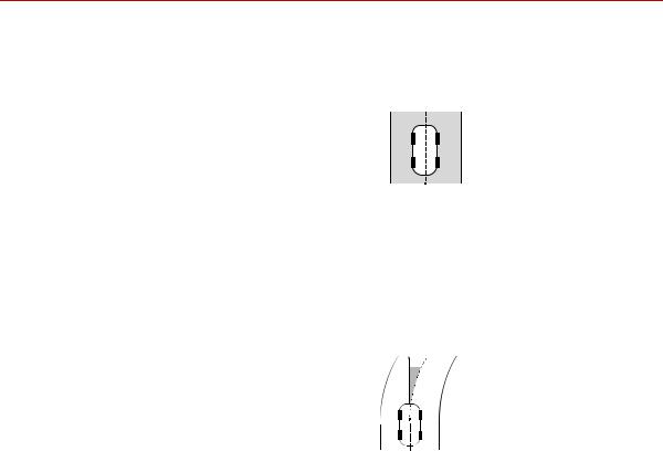
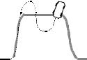
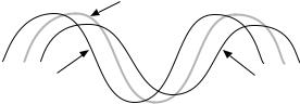
To understand how tuning works, consider the analogy of taking a car on the highway. The dashed line down the middle of the road is where the driver wants to be—so this is the command.
This is an automated system that tells the driver if the car is following the command and, if not, how far it is off and in what direction. As the car moves, the road begins to curve. The driver does not respond immediately, so the command (the desired path) and the feedback (the actual path) are starting to differ.
This difference (command minus feedback) is error. It is indicated by the shaded triangle.
Note that error increases the longer the driver waits to correct it, that is, the larger the difference between the desired path and the actual path.The driver turns the steering wheel to adjust the car’s path. But there is a problem.
Note Assume the error detector is set to a value that represents the width of the road. If the response is too slow or too quick, the error detector can stop the program before you go off the road.
20 Introduction |
MTS Series 793 Tuning and Calibration |
The test waveform
The ultimate goal
About Tuning
If you turn the steering wheel too little, and the car responds too slowly. If you turn the steering wheel too much, the car overresponds. So the objective for a good driver is to turn the wheels just right. If so, the car accurately follows the line, the passengers have a smooth ride.
We want our servo loop to work just like the skilled driver, that is, to turn the steering wheel just the right amount.
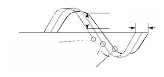
Now imagine the road transformed into the square wave shown in the diagram, which is one type of test waveform. We want our test (the car) to follow the desired command (the road) in all respects. That means the test system should exert the precise force (or displacement or strain) that we want on the specimen.
The only problem is that different types of materials—from the softest to the hardest—exhibit different reactions to the force or displacement or strain. Just as we would tune a car differently for racing than we would for a weekly drive to the store, the tuning differs too. A system properly tuned for a soft specimen will go unstable if you install a very hard specimen.
Get the error signal to be as small as possible at all times (without compensators), because:
•The error signal tells the servovalve to open.
•The larger the error signal, the more the servovalve opens.
•Therefore, if the error is zero, the servovalve is closed. This means the servo loop is “satisfied” and all is well.
Remember: If the error is as close to zero as possible (actually maintaining zero is impossible), it indicates that the system is closely following the command.
MTS Series 793 Tuning and Calibration |
Introduction 21 |
About Tuning
Getting there |
• |
Start with the command. |
|
|
• |
Add the feedback—it lags the command. |
|
|
• |
Adjust to get the error and phase shift as low as possible. |
|
|
|
|
Time Lag |
|
|
Error |
(phase shift) |
Program Command
Feedback (higher Proportional gain)
Feedback (lower Proportional gain)
22 Introduction |
MTS Series 793 Tuning and Calibration |
About Tuning
Proportional (P) Gain
Proportional gain is the primary and coarsest control of the system. It is similar to a radio’s volume control in that it amplifies the error signal by an appropriate amount to control the system. In its most generic sense, the term proportional gain means that the change in power output is proportional to the error.
Remember that for our car, the amount of steering (amplitude) is proportional to how much we want to correct, and how fast. This is proportional gain. Our formula is now:
Error = Gain x (Command - Feedback)
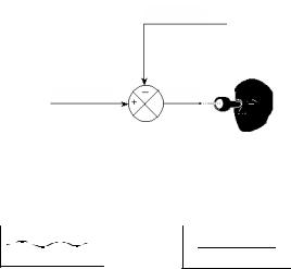
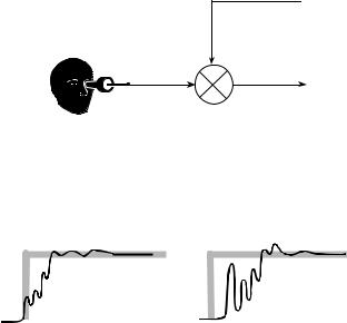
Feedback
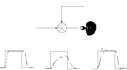
Command Error
Proportional gain looks at the Error side of the summing junction.
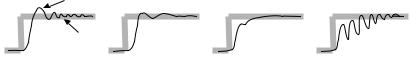
The shaded square wave represents the test command. The solid waveform shows an idealized feedback signal.
This waveform shows a sluggish (low gain) feedback signal.
This waveform shows an unstable (high gain) feedback signal.
Note Proportional gain is not speed (how far your push down on the gas pedal), it is how fast you turn the steering wheel. So proportional gain in the servo loop is acceleration. The “speed” of the system is controlled by the size of the hydraulic components.
MTS Series 793 Tuning and Calibration |
Introduction 23 |
About Tuning
More about Proportional gain
At first, it may seem desirable to make proportional gain as large as possible. After all, we want the system to react quickly and positively. One sign of a system with insufficient proportional gain is that it is sluggish.
There is only one problem with having proportional gain higher than necessary: it is very difficult to keep the car on the road. It flies off, we overcontrol trying to correct it, and the cycle continues. A servo loop can do that too; it is said to be ringing. It is unstable. There is nothing subtle about an unstable loop—you will hear it. If the test fixture is large enough, you will feel it too.
So as a general rule, the gain should be as high as possible without causing the loop to go unstable. General principles to remember are:
•With a given error signal, increasing the gain increases the input to the servovalve.
•Increasing the input to the servovalve opens it more.
•Opening the servovalve more moves the oil faster into the actuator.
•Moving oil faster makes the loop respond quicker, reducing the error faster.
Proportional gain is used for all tuning situations. It introduces a control factor that is proportional to the error signal. Proportional gain increases system response by boosting the effect of the error signal on the servovalve.
Keep in mind:
•As proportional gain increases, the error decreases and the feedback signal tracks the command signal more closely.
•Higher gain settings increase the speed of the system response.
•Too much proportional gain can cause the system to become unstable, while too little proportional gain can cause the system to become sluggish.
•Gain settings for different control modes may vary greatly. For example, the gain for force may be as low as 1 while the gain for strain may be as high as 10,000.
24 Introduction |
MTS Series 793 Tuning and Calibration |
About Tuning
Integral (I) Gain
Integral gain generates increased gain over longer time spans (including steady state). Integral gain is sometimes called Reset gain.
To return to the car analogy: The race is over. You’ve won and the trip home is an easy one. You’re driving on a straight highway so you are not being as attentive as when you were racing.
The car drifts off of its desired path. The problem is that this happens so slowly that you don’t realize it. You need something to boost your attention.
That’s what integral gain is, or why it is sometimes called Reset Integration. It is the integral of the error signal, that is, it is essentially the error signal multiplied by time. This means that even a small error signal eventually will become conspicuous.
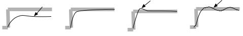
Feedback
Command Error
Intergral (Reset) gain looks at the error side of the summing junction. It is the integral of the error, indicating the size of the error over time.
More about Integral gain (I)
too much integral gain |
dc stability |
An error signal made |
An error signal that is |
unstable by too much |
stabilized by correct gain. |
integral gain. |
|
Integral gain introduces “an integral of the error signal” that gradually, over time, boosts the low-frequency response of the servovalve command.
MTS Series 793 Tuning and Calibration |
Introduction 25 |
About Tuning
Integral gain increases system response during static or low-frequency operation and maintains the mean level at high-frequency operation. It can offset a DC or steady-state error, such as that caused by valve imbalance.
Droop |
|
Overshoot |
Hunting |
|
|
|
|
Reset Too Low |
Mean Level Stability |
Reset Too High |
Excessive Reset |
A ramp and hold waveform illustrate different levels of reset. The
I Gain adjustment determines how much time it takes to improve the mean level accuracy.
Integral gain:
•Improves mean level response during dynamic operation
•Corrects feedback droop caused by the spring characteristic of the servovalve in static and very low-frequency test programs
•Minimizes the amount of time the system needs to recover from transitions or transients
Keep in mind:
•Higher integral gain settings increase system response.
•Too much integral gain can cause a slow oscillation (hunting).
•You may want to use the max/min display to monitor the mean level, reset the display, and check it again.
Integrator limit The Integrator Limit control allows you to set the maximum integrator value as a percentage of full-scale output.
Derivative (D) Gain
Derivative gain is an adjustment you may or may not need. Another name for derivative gain is Rate gain.
Get back into the car and back on the race track. Only now you are going really fast and the curves are electrifying. But it is a race, so you are actually accelerating while in the short straightaways.
26 Introduction |
MTS Series 793 Tuning and Calibration |
About Tuning
In your attempt to accelerate, you press the gas pedal all the way to the floor— and hold it there. But now you are going too fast to safely round a curve, so you slam on the brakes just as you enter the curve, then release them. The brakes stabilize the trip by restraining the driving action at the time that the car is changing direction. Consider this: you barely need brakes if going slowly down a wide, level street. Brakes become more essential the faster you go and the quicker you change direction. Derivative gain is the same concept. It stabilizes the system by reducing the error signal when its rate of change is the greatest. This reduces overshoot and ringing at high proportional gain settings.
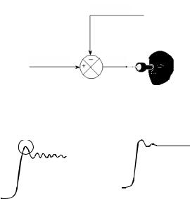
Feedback
Command Error
Derivative gain looks at the feedback side of the summing junction. It is the derivative of that signal, indicating how fast the feedback is changing.
Here is a signal with a high degree of proportional gain. Derivative gain has not been applied yet. Notice how noisy the signal is.
The same high gain signal after derivative gain has been applied. The derivative gain tends to damp out the ringing.
So, derivative gain indicates the change in acceleration in the error signal. Or, in an equation:
Derivative Gain = Gain x (Command - Feedback)'
(The ' symbol in the equation above means “first derivative.”)
MTS Series 793 Tuning and Calibration |
Introduction 27 |
About Tuning
Do you need derivative There is a good chance you do not. It is used primarily in systems performing gain? dynamic tests. Consider this scenario: You have a specimen that is quite springy
(such as fiberglass). The test is calling for rapid changes in direction (say, for example, more than 5 times a second) and high velocities. Proportional gain needs to be set quite high to get this kind of response. Because things are changing so rapidly, the system is electrically noisy. If the system is making a rumbling sound, you could use some derivative gain.
On the other hand, it is unlikely for you to need derivative gain for soft materials such as elastomers.
Another quick (and incomplete) rule-of-thumb is to write down the ratings of your actuator and servovalve in kips and gallons per minute. If kip ÷ gpm>1, then derivative gain probably has little effect on the loop.
More about derivative Derivative gain is used with dynamic test programs. It introduces a “derivative of gain the feedback signal.” This means it anticipates the rate of change of the feedback
and slows the system response at high rates of change.
Overshoot |
|
|
|
Ringing |
|
|
|
Needs Rate |
Optimum Rate |
More than |
Excessive Rate |
|
|
Optimal Rate |
|
Derivative gain:
•Reduces ringing.
•Provides stability and reduces noise at higher proportional gain settings.
•Tends to amplify noise from sensors.
•Tends to decrease system response when set too high.
Keep in mind:
•Too much derivative gain can create instability at high frequencies, and too much proportional gain may cause a ringing or screeching sound.
•Too little derivative gain can make a rumbling sound. The correct amount of derivative gain results in the system running quietly.
Note Series 256 and 257 Servovalves may require derivative gain applied to both the inner control loop and outer control loop.
28 Introduction |
MTS Series 793 Tuning and Calibration |
About Tuning
Note Excessive negative (–) D Gain can cause your system to become unstable.
Feed Forward (F or F2) Gain
Feed Forward is a gain adjustment not needed for many systems. It is more likely needed on systems where you need to move a lot of oil fast to get the actuator moving. So it is more likely to be found on systems with large actuators, massive grips, or moving load cells. For our car example, and if you remember how carburetors work, feed forward is equivalent to the accelerator pump—that is the gizmo that gives a quick slug of gas when you suddenly floor the gas pedal.
This mode is like Derivative mode, except that it anticipates changes rather than reacts to them.
Feed forward watches the command side of the summing junction, and provides a derivative of the command. Remember that a derivative is proportional to the rate of change of a signal; therefore, the faster the command is changing (like during the leading/trailing edges of a squarewave), the greater the signal is.
Feedback
Command |
Error |
|
Feed forward gain looks at the command side of the summing junction. The output is the derivative of that signal, indicating how fast the command is changing.
Correct feed forward. |
Inadequate feed forward. |
So look at feed forward as a form of a “predictor” of where the actuator should be going. The signal gives the servovalve an early indicator to tell it that it needs to open faster than would be expected from the existing error signal.
MTS Series 793 Tuning and Calibration |
Introduction 29 |
About Tuning
More about Feed Feed forward (F/F2 Gain) introduces a derivative of the command signal. It Forward Gain anticipates how large a valve opening is needed to reach the required response
and adds that to the valve command—like compensating for phase lag.
F Gain vs. F2 Gain F Gain is applied to the current control mode before the forward loop filter. F2 Gain is applied after the forward loop filter.
When your forward loop filters are set to low frequencies it tends to limit the effectiveness of F Gain. F2 Gain may work better in this situation.
You would tend to use F Gain when there are frequencies you do not wish to excite. Using F Gain allows the forward loop filter to filter out these frequencies.
Adjusting F Gain or F2
Gain causes the command |
|
Original Command |
|
|
|
signal to start sooner. This |
|
|
causes the feedback signal |
|
|
to track the original |
|
|
command signal more |
|
|
closely. |
Feed Forward Command |
Original Feedback |
F/F2 Gain |
• |
Does not compensate for normal changes during testing (such as |
|
|
temperature changes, servovalve droop, and so forth). |
|
• |
May be used to minimize phase lag. |
|
• |
Should be used like derivative gain. However, F Gain applies to the test |
|
|
command signal while derivative gain applies to the feedback signal. |
|
• |
Feed forward gain helps the servo-control loop react quickly to an abrupt |
|
|
change in the command. |
|
• |
Is needed when testing a soft specimen in force control. |
Stabilization Gain (S Gain)
Stabilization gain allows a second signal to be integrated into the composite command signal as a stabilizing factor. It enhances stability for systems that move large masses at high speeds. The second signal is generated by a special transducer such as P (differential pressure) or accelerometer.
Stabilization controls will be available only if a stabilization resource was added to the control channel.
30 Introduction |
MTS Series 793 Tuning and Calibration |
Loading...