


 Loading...
MTS TestSuite
TW Elite Test Design Guide
100-234-122 G |
be certain. |
© 2014 MTS Systems Corporation. All rights reserved.
Trademark Information
MTS is a registered trademark of MTS Systems Corporation within the United States. This trademark may be protected in other countries.All other trademarks or service marks are property of their respective owners.
Proprietary Software
Software use and license is governed by MTS’s End User License Agreement which defines all rights retained by MTS and granted to the End User. All Software is proprietary, confidential, and owned by MTS Systems Corporation and cannot be copied, reproduced, disassembled, decompiled, reverse engineered, or distributed without express written consent of MTS.
Software Verification and Validation
MTS software is developed using established quality practices in accordance with the requirements detailed in the ISO 9001 standards. Because MTS-authored software is delivered in binary format, it is not user accessible. This software will not change over time. Many releases are written to be backwards compatible, creating another form of verification.The status and validity of MTS’s operating software is also checked during system verification and routine calibration of MTS hardware. These controlled calibration processes compare the final test results after statistical analysis against the predicted response of the calibration standards. With these established methods, MTS assures its customers that MTS products meet MTS’s exacting quality standards when initially installed and will continue to perform as intended over time.
Manual Part Number—Publication Date—Release
100-234-122 G—February 2014—MTS TestSuite TW 2.3.4 or later 100-234-122 F—September 2013—MTS TestSuite TW 2.3.1 100-234-122 E—August 2013—MTS TestSuite TW 2.3 100-234-122 D—January 2013—MTS TestSuite TW 2.2 100-234-122 C—December 2012—MTS TestSuite TW 2.1
|
Table of Contents |
Table of Contents |
|
Preface |
|
Before You Begin............................................................................................................................................. |
7 |
Documentation Conventions............................................................................................................................ |
7 |
Technical Support |
|
How to Get Technical Support....................................................................................................................... |
11 |
Before You Contact MTS............................................................................................................................... |
11 |
If You Contact MTS by Phone....................................................................................................................... |
13 |
Problem Submittal Form in MTS Manuals.................................................................................................... |
14 |
Introduction |
|
About This Guide........................................................................................................................................... |
16 |
Start TWE and Open the Example Test.......................................................................................................... |
17 |
TWE Main Window....................................................................................................................................... |
17 |
Main Window Toolbar....................................................................................................................... |
20 |
About the Multi-Head Run Section.................................................................................................... |
21 |
Multi-Head Run Section Properties................................................................................................... |
22 |
Examine the Example Test |
|
About this Chapter......................................................................................................................................... |
26 |
Design Flow................................................................................................................................................... |
26 |
Define Tab...................................................................................................................................................... |
27 |
Outline View in the Procedure Subtab............................................................................................... |
27 |
Workflow in the Procedure Subtab.................................................................................................... |
28 |
Set Up Section........................................................................................................................ |
29 |
Run Section............................................................................................................................ |
30 |
Examining the Logic in the Run Section................................................................................ |
32 |
Program Command in the Example Test................................................................................ |
33 |
Branches in the Parallel Paths Activity.................................................................................. |
34 |
Go To + DAQ + Detection Activity....................................................................................... |
35 |
Finish Section......................................................................................................................... |
39 |
Test-Run Display Subtab.................................................................................................................... |
40 |
Variables Subtab................................................................................................................................. |
40 |
Variable Definition................................................................................................................. |
41 |
Variable Use in the Example Test........................................................................................... |
41 |
Variable Availability Attributes.............................................................................................. |
42 |
Report Templates Subtab.................................................................................................................... |
43 |
Functions Subtab................................................................................................................................ |
44 |
3
Table of Contents |
|
Resources Subtab............................................................................................................................... |
45 |
Test Definition Subtab........................................................................................................................ |
47 |
Monitor Tab.................................................................................................................................................... |
49 |
Review Tab Layout........................................................................................................................................ |
51 |
Review Tab Toolbar........................................................................................................................... |
52 |
Test Run Results Table....................................................................................................................... |
53 |
Statistics Table.................................................................................................................................... |
54 |
Panel of Charts and Tables................................................................................................................. |
54 |
Four-Panel View................................................................................................................................. |
56 |
Runtime Values Tab........................................................................................................................................ |
57 |
Design Guidelines |
|
About this Chapter......................................................................................................................................... |
60 |
Designing Tests.............................................................................................................................................. |
60 |
Test Design Checklist......................................................................................................................... |
60 |
Tests and Templates............................................................................................................................ |
61 |
Choosing a Template to Run or Modify................................................................................. |
61 |
File Icons................................................................................................................................ |
61 |
Working with Templates and Tests......................................................................................... |
62 |
Modifying Tests.................................................................................................................................. |
63 |
Adding and Configuring Test Activities................................................................................ |
63 |
Considerations for Test Sections ........................................................................................... |
65 |
Configuring What is Displayed After Test Runs.................................................................... |
67 |
Interacting with the Operator During Tests............................................................................ |
67 |
Run-Time Markers................................................................................................................. |
67 |
Batch Mode Tests................................................................................................................... |
67 |
Pre-Allocating Multiple Test Runs......................................................................................... |
68 |
Working With Variables..................................................................................................................... |
69 |
Variable Concepts .................................................................................................................. |
69 |
Benefits of Using Variables.................................................................................................... |
69 |
Using Variables in Activities.................................................................................................. |
70 |
Toggling Between Static Values and Variables...................................................................... |
70 |
Variable Example................................................................................................................... |
70 |
Manipulating Variables in the Workflow .............................................................................. |
71 |
Assigning Variable Availability.............................................................................................. |
72 |
Adding Calculations to Variables .......................................................................................... |
72 |
Managing Variables................................................................................................................ |
73 |
Used By Table Column.......................................................................................................... |
74 |
Configuring Data Acquisition............................................................................................................ |
74 |
Data Acquisition Properties Page........................................................................................... |
74 |
Mapping Variables to Acquired Data..................................................................................... |
74 |
Acquiring Data in a Continuous Stream................................................................................. |
75 |
4
|
Table of Contents |
Acquiring Data in Blocks Without Mode Switching............................................................. |
75 |
Acquiring Data in Blocks With Mode Switching................................................................... |
75 |
Setting Buffer Size................................................................................................................. |
75 |
Data Acquisition for Test-Run Displays................................................................................ |
76 |
Polarity Considerations for MTS Criterion Series 40 Systems ......................................................... |
76 |
Debugging.......................................................................................................................................... |
78 |
Automatic Saves and Experimentation.................................................................................. |
79 |
Rapid Design Iterations.......................................................................................................... |
79 |
Activity State in Outline View............................................................................................... |
79 |
Test Procedure Test-Run Display........................................................................................... |
79 |
Runtime Values Tab................................................................................................................ |
79 |
Modify the Example Test |
|
About this Chapter......................................................................................................................................... |
82 |
Modifying Tests.............................................................................................................................................. |
82 |
Design Scenario.............................................................................................................................................. |
83 |
Modifying the Set Up Section............................................................................................................ |
83 |
Formula Assistant File........................................................................................................... |
84 |
Changing the Specimen Geometry......................................................................................... |
84 |
Adding an Input Variables Activity ....................................................................................... |
86 |
Moving and Enabling Run External Application Activity..................................................... |
88 |
Modifying the Run Section................................................................................................................ |
88 |
Enable and Configure the Custom Message Window Activity.............................................. |
89 |
Editing the Go To + DAQ + Detection Activity ................................................................... |
90 |
Modifying the Finish Section............................................................................................................. |
92 |
Changing the Maximum Test Runs Variable.......................................................................... |
92 |
Enabling and Configuring the Run Report Activity............................................................... |
93 |
Working with MTS FlexTest Resources |
|
Resource Basics.............................................................................................................................................. |
96 |
Connecting to a Controller............................................................................................................................. |
96 |
Creating a Desktop Shortcut That Includes a Controller............................................................................... |
98 |
Station Configurations.................................................................................................................................... |
98 |
Controller Resources...................................................................................................................................... |
99 |
Resource Mapping.......................................................................................................................................... |
99 |
Offline Test Design...................................................................................................................................... |
102 |
Resources That Allow Dimension Changes................................................................................................. |
103 |
Considerations for Servohydraulic Systems |
|
Understand Software Concepts.................................................................................................................... |
106 |
Using MTS TestSuite with Controller Software.......................................................................................... |
106 |
5
Table of Contents |
|
Station Controls Panel...................................................................................................................... |
107 |
Station Configuration Files.............................................................................................................. |
108 |
TWE Startup..................................................................................................................................... |
109 |
Working with Limits........................................................................................................................ |
109 |
Set Station Detector Limits.................................................................................................. |
110 |
Access and Set Detector Settings......................................................................................... |
110 |
Reset Detectors..................................................................................................................... |
112 |
Using Manual Command to Install the Specimen............................................................................ |
112 |
Manual Command Properties............................................................................................... |
112 |
Manually Position the Actuator............................................................................................ |
114 |
Applying Offsets to the Input Signal (optional)............................................................................... |
115 |
Apply an Auto Offset to an Input Signal.............................................................................. |
115 |
Apply a Manual Offset to an Input Signal........................................................................... |
115 |
TW Elite for TestWorks 4 Users |
|
About this Chapter....................................................................................................................................... |
118 |
Basic Concepts............................................................................................................................................. |
118 |
Terminology Differences.............................................................................................................................. |
119 |
Functional Differences................................................................................................................................. |
122 |
Converting TestWorks 4 Methods and Sample Files................................................................................... |
125 |
Conversion Issues for MTS FlexTest Controllers........................................................................................ |
125 |
6
Preface
Before You Begin
Safety first!
Before you use your MTS product or system, read and understand the safety information provided with your system. Improper installation, operation, or maintenance can result in hazardous conditions that can cause severe personal injury or death, or damage to your equipment and specimen. Again, read and understand the safety information provided with your system before you continue. It is very important that you remain aware of hazards that apply to your system.
Other MTS manuals
In addition to this manual, you may receive additional manuals in paper or electronic form.
You may also receive an MTS System Documentation CD. It contains an electronic copy of the manuals that pertain to your test system.
Controller and application software manuals are typically included on the software CD distribution disc(s).
Documentation Conventions
The following paragraphs describe some of the conventions that are used in your MTS manuals.
Hazard conventions
Hazard notices may be embedded in this manual. These notices contain safety information that is specific to the activity to be performed. Hazard notices immediately precede the step or procedure that may lead to an associated hazard. Read all hazard notices carefully and follow all directions and recommendations. Three different levels of hazard notices may appear in your manuals. Following are examples of all three levels. (for general safety information, see the safety information provided with your system.)
Danger:
Danger notices indicate the presence of a hazard with a high level of risk which, if ignored, will result in death, severe personal injury, or substantial property damage.
MTS TestSuite | 7

Preface
Warning:
Warning notices indicate the presence of a hazard with a medium level of risk which, if ignored, can result in death, severe personal injury, or substantial property damage.
Caution:
Caution notices indicate the presence of a hazard with a low level of risk which, if ignored, could cause moderate or minor personal injury or equipment damage, or could endanger test integrity.
Other special text conventions
Important:
Important notices provide information about your system that is essential to its proper function. While not safety-related, if the important information is ignored, test results may not be reliable, or your system may not operate properly.
Note:
Notes provide additional information about operating your system or highlight easily overlooked information.
Recommended:
Recommended notes provide a suggested way to accomplish a task based on what MTS has found to be most effective.
Tip:
Tips provide helpful information or a hint about how to most efficiently accomplish a task.
Access:
Access provides the route you should follow to a referenced item in the software.
Examples show specific scenarios relating to your product and appear with a shaded background.
Special terms
The first occurrence of special terms is shown in italics.
Illustrations
Illustrations appear in this manual to clarify text. They are examples only and do not necessarily represent your actual system configuration, test application, or software.
8 | MTS TestSuite
Preface
Electronic manual conventions
This manual is available as an electronic document in the Portable Document File (PDF) format. It can be viewed on any computer that has Adobe Acrobat Reader installed.
Hypertext links
The electronic document has many hypertext links displayed in a blue font. All blue words in the body text, along with all contents entries and index page numbers, are hypertext links. When you click a hypertext link, the application jumps to the corresponding topic.
MTS TestSuite | 9
Technical Support
How to Get Technical Support
Start with your manuals
The manuals supplied by MTS provide most of the information you need to use and maintain your equipment. If your equipment includes software, look for online help and README files that contain additional product information.
Technical support methods
MTS provides a full range of support services after your system is installed. If you have any questions about a system or product, contact Technical Support in one of the following ways.
Web site |
www.mts.com > Contact Us (upper-right corner) > In the Subject field, choose |
|
To escalate a problem; Problem Submittal Form |
Worldwide: tech.support@mts.com |
|
|
Europe: techsupport.europe@mts.com |
Telephone |
Worldwide: 1 800 328 2255 - toll free in U.S.; +1 952 937 4000 - outside U.S. |
|
Europe: +800 81002 222, International toll free in Europe |
Outside the U.S.
For technical support outside the United States, contact your local sales and service office. For a list of worldwide sales and service locations and contact information, use the Global MTS link at the MTS web site:
www.mts.com > Global Presence > Choose a Region
Before You Contact MTS
MTS can help you more efficiently if you have the following information available when you contact us for support.
Know your site number and system number
The site number contains your company number and identifies your equipment type (such as material testing or simulation). The number is typically written on a label on your equipment before the system leaves MTS. If you do not know your MTS site number, contact your sales engineer.
Example site number: 571167
MTS TestSuite | 11
Technical Support
When you have more than one MTS system, the system job number identifies your system. You can find your job number in your order paperwork.
Example system number: US1.42460
Know information from prior technical assistance
If you have contacted MTS about this problem before, we can recall your file based on the:
•MTS notification number
•Name of the person who helped you
Identify the problem
Describe the problem and know the answers to the following questions:
•How long and how often has the problem occurred?
•Can you reproduce the problem?
•Were any hardware or software changes made to the system before the problem started?
•What are the equipment model numbers?
•What is the controller model (if applicable)?
•What is the system configuration?
Know relevant computer information
For a computer problem, have the following information available:
•Manufacturer’s name and model number
•Operating software type and service patch information
•Amount of system memory
•Amount of free space on the hard drive where the application resides
•Current status of hard-drive fragmentation
•Connection status to a corporate network
Know relevant software information
For software application problems, have the following information available:
•The software application’s name, version number, build number, and (if available) software patch number. This information can typically be found in the About selection in the Help menu.
•The names of other applications on your computer, such as:
—Anti-virus software
—Screen savers
—Keyboard enhancers
—Print spoolers
12 | MTS TestSuite

Technical Support
— Messaging applications
If You Contact MTS by Phone
A Call Center agent registers your call before connecting you with a technical support specialist. The agent asks you for your:
•Site number
•Name
•Company name
•Company address
•Phone number where you can be reached
If your issue has a notification number, please provide that number. A new issue will be assigned a unique notification number.
Identify system type
To enable the Call Center agent to connect you with the most qualified technical support specialist available, identify your system as one of the following types:
•Electrodynamic material test system
•Electromechanical material test system
•Hydromechanical material test system
•Vehicle test system
•Vehicle component test system
•Aero test system
Be prepared to troubleshoot
Prepare to perform troubleshooting while on the phone:
•Call from a telephone close to the system so that you can implement suggestions made over the phone.
•Have the original operating and application software media available.
•If you are not familiar with all aspects of the equipment operation, have an experienced user nearby to assist you.
Write down relevant information
In case Technical Support must call you:
•Verify the notification number.
•Record the name of the person who helped you.
MTS TestSuite | 13

Technical Support
•Write down any specific instructions.
After you call
MTS logs and tracks all calls to ensure that you receive assistance for your problem or request. If you have questions about the status of your problem or have additional information to report, please contact Technical Support again and provide your original notification number.
Problem Submittal Form in MTS Manuals
Use the Problem Submittal Form to communicate problems with your software, hardware, manuals, or service that are not resolved to your satisfaction through the technical support process. The form includes check boxes that allow you to indicate the urgency of your problem and your expectation of an acceptable response time. We guarantee a timely response—your feedback is important to us.
You can access the Problem Submittal Form at www.mts.com > Contact Us (upper-right corner) > In the
Subject field, choose To escalate a problem; Problem Submittal Form
14 | MTS TestSuite

Introduction
Topics: |
|
|
• |
About This Guide............................................................................................................................... |
16 |
• Start TWE and Open the Example Test............................................................................................ |
17 |
|
• |
TWE Main Window............................................................................................................................ |
17 |
MTS TestSuite | 15

Introduction
About This Guide
The MTS TestSuite TW Elite Test Design Guide contains the information you need to begin customizing templates with the TW Elite (TWE) application. It includes the fundamental concepts of using the TWE application with MTS control software to create and run tests.
This guide does not explain every TWE application feature. Its goal is to introduce the most important features of the application in the context of customizing tests.
Summary
Introduction: Provides an overview of the TWE interface. In this section, you will open the example test included with the TWE application. The example test was created to run in simulation and includes test run data. This section describes the basic parts of the interface with the example test loaded.
Examine the Example Test: Examines the example test supplied with the system in detail. Understanding the example test reveals application capabilities and design principles you can apply to your own tests.
Design Guidelines: Provides design guidelines for TWE tests in general.
Modify the Example Test: Provides a tutorial for how to modify the example test with typical enhancements using the design guidelines, tips, and best practices.
Working with MTS FlexTest Resources: Provides information for mapping test resources to MTS FlexTest controller resources.
Considerations for Servohydraulic Systems: Provides information for using TWE with MTS FlexTest controllers for use in servohydraulic test systems.
MTS TWE for TestWorks 4 Users: Provides information to help users of MTS TestWorks 4 transition to TWE.
Information pertaining to MTS TW Express
MTS offers a companion application to TW Elite named TW Express (TWX). TWX cannot be used to create or modify tests; it can only run existing tests. In cases where this manual refers to functionality shared by both applications (such as running tests), the term "TW application" is used.
Information pertaining to MTS Insight and MTS FlexTest controllers
The TWE application can be used with MTS Insight controllers on electromechanical systems and with MTS FlexTest controllers on servohydraulic systems. The information in Examine the Example Test (p. 25) and Modify the Example Test (p. 81) is based on the example test supplied with the system which runs on the MTS Insight controller in simulation. Information pertaining to systems used with MTS FlexTest controllers is provided in Working with MTS FlexTest Resources (p. 95).
For More Information
Examine the Example Test (p. 25)
Modify the Example Test (p. 81)
Working with MTS FlexTest Resources (p. 95)
16 | MTS TestSuite

Introduction
Start TWE and Open the Example Test
Install TWE in simulation
Installation of TWE consists of running a self-extracting executable file. When running the MTS TestSuite InstallShield wizard, ensure you select “Insight/Criterion Simulation” when choosing the controller type.
Note:
The following startup procedure is for electromechanical systems. For servohydraulic systems, see
TWE Startup (p. 109).
Open the Example MTS EM Tension (Simplified) Test
1. Start the TWE application.
TW Elite Icon
Double-click the TWE icon on your desktop, or click Start > Programs > MTS TestSuite > TW Elite. The application opens and connects to the simulated MTS Insight controller (the MTS Insight icon appears on the taskbar).
Note:
The example test is in Project 1, which is the default project. If Project 1 is not selected as the default project, select Preferences > Configuration > Project > Project 1, right-click the mouse, and then select Set as System Default Project.
2.The application automatically opens to the Select tab. In the Tests directory, open the Example MTS EM Tension (Simplified) Test.
Note:
As a test designer, you typically log on to the TWE application as an Engineer or Administrator. When you open a test, the main window displays the workflow. If you open a test while logged on to TWE as an Operator, or when you open a test with the TW Express (TWX_ application, the workflow is hidden, and the main window shows the test inputs on the Monitor tab.
For More Information
TWE Startup (p. 109)
TWE Main Window
When you open a test, the application shows the workflow in the Define tab. Review the basic features in the TWE application as shown in the following figures and tables.
MTS TestSuite | 17

Introduction
TWE Application Main Window
TWE Main Window Description
Number Item |
Description |
1Menu bar and Provides menus and quick-access icons that allow you to perform tasks Quick Access such as opening tests, opening tests from templates, and saving tests
panel |
as templates. |
2Control panel Allows you to resolve interlocks; display fault status; view the direction
in which the crosshead is moving; position the crosshead; and start, stop, and hold the test.
Note: When control is provided by a handset, the crosshead controls will be locked and overlaid by the handset exclusive control icon:
3Status panel Shows test run information, including name, status, and running time.
This panel includes a control that allows you to terminate the current test run.
18 | MTS TestSuite

|
|
Introduction |
Number |
Item |
Description |
4 |
Toolbox panel (not |
The contents of the Toolbox panel change depending on the subtab |
|
shown) |
selected in the Define tab: |
|
|
• When you select the Procedure subtab, the Toolbox panel contains |
|
|
components that pertain to test activities such as commands, data |
|
|
acquisition, test flow control, and program actions. |
|
|
• When you select the Test-Run Display subtab, the Toolbox panel |
|
|
contains components that pertain to the display of test data, such as |
|
|
cycle, variable, and signal views. |
5Outline button The Outline button displays a hierarchical view of the test in the center
|
|
panel when selected. |
6 |
Workflow |
Provides a work area to edit tests. You drag test activities from the |
toolbox to the workflow to edit tests. The workflow contains three sections: Set Up, Run, and Finish.
• Use the Set Up section for activities that you want to perform before you start test runs, such as configuring the load train (setting up fixtures, etc.) and entering a test name. The Set Up section runs only once when you start a test, that is, before the first test run in the test.
• Use the Run section for applying forces to the specimen while performing test runs. The Run repeats for all test runs in the test, and by default shows the Review tab after every test run.
If you are using a multi-head frame and template, your workarea will show a Multi-Head Run section instead of a Run section. For more information about the Multi-Head Run section, see About the Multi-Head Run Section (p. 21).
• Use the Finish section for operations such as printing reports, exporting files, saving test data, and archiving. The Finish section runs when the number of test runs set for the test is complete, or when the operator clicks the Run Finish Section button on the Review tab.
Note:
The workflow includes Pan and Zoom features to help you view complex test procedures.
7Properties panel Allows you to define or change the information, characteristics, and
appearance of the selected procedure activities and runtime display components. For example, you can use the Properties panel to change the amplitude of a cycle command test activity in a procedure, or the Y-axis signal selection on a signal scope in a test-run display.
MTS TestSuite | 19
Introduction
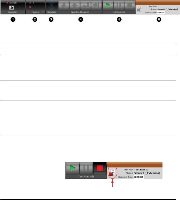
Main Window Toolbar
TWE Application Main Toolbar
Application Toolbar Description
Number Item |
Description |
1Controller panel Allows you to reset interlocks.
2 |
Status panel |
Shows fault status information. This indicator is primarily for diagnosing |
|
|
system errors with MTS service personnel. |
3Direction panel Indicates when the crosshead/actuator is moving and in what physical
|
|
direction. This relates to physical motion, regardless of whether feedback |
|
|
is increasing or decreasing. |
4 |
Crosshead |
Contains controls that allow you to move the crosshead up and down |
|
Controls panel |
for specimen installation, and for returning the crosshead to the zero or |
|
|
a preset location. |
5Test Controls Contains controls to run, hold, and stop the test run. panel
6Status panel Shows test run information, including name, status, and running time.
It includes a Cancel Test Run button you can use to terminate the current test run. When the test is stopped, pressing this button terminates the current test run. Pressing the Run button starts a new test run.
Status Panel with Cancel Test Run Button
20 | MTS TestSuite
Introduction
About the Multi-Head Run Section
Note:
The Multi-Head option is a separately licensed feature.
Note:
Prerequisite: Only analog data is collected from the multiple active load cells in a multi-head frame. You must have National Instruments Data Acquisition (Ni-DAQ) hardware and software or an extensometer installed which will convert the analog data to digital signals.
Multi-head frames can contain up to five active load cells which allow the simultaneous collection of test-runs for multiple specimens. By default, the test run collects the results for all specimens within one file. You can create a separate test-run file for each of the specimens by using the appropriate multi-head template which contains the Multi-Head Run section in the test procedure work area. This section is similar to the Run section found in templates for single head frames which contains activities for applying forces to the specimen while performing test runs. Unlike the Run section, the Multi-Head Run section contains a Properties Panel where you can input configuration data. The Multi-Head Run is only run once. Data is collected simultaneously from the Ni-DAQ analog signals. After the test is completed, the data is split into multiple tests runs. At the end of the test, a number of test runs will be created and populated with the collected data. The new test runs appear post-test as if they were individually collected.
At the end of the multi-head test, the array data is split into multiple test-run files by moving the collected data into the normal force, extension, and optional strain variables.
To create a new multi-head template, you must start with an existing test or template that contains the Multi-Head Run section. To save a test as a template, you must be assigned the Administrator or Engineer privilege.
MTS TestSuite | 21
Introduction
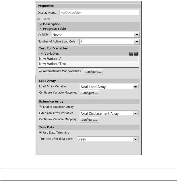
Multi-Head Run Section Properties
|
Multi-Head Run Section Properties |
Item |
Description |
Number of Active Load Cells Specify how many test-runs should be created. For example, if you are testing four specimens, enter 4. When the test run has ended, four test run files will be created. Default: 5
Click the Automatically Map Variables checkbox to have the system map variables, or click the Configure button to open the Map Variables window and manually map variables.
22 | MTS TestSuite

|
Introduction |
Item |
Description |
|
Note: |
|
If you select the Automatically Map option and then change the |
|
Number of Active Load Cells value, some variables will be |
|
created or removed. |
|
If you map variables manually, and then select Auto Map |
|
Variables, your manually created variables will be overwritten |
|
by the automatically-generated variables. |
Test Run Variables |
Specify variables that are not in the Common category. For example, |
|
if Number of Active Load Cells is 5 and the Width variable is added |
|
to this list, the other five variables should be mapped to the Width |
|
variable (such as Width1, Width2… Width5). At the end of the test, the |
|
variable values from Width1, Width2, and so on, must be moved to the |
|
Width variable in the appropriate test runs. Click the green plus sign to |
|
add a variable. To delete a variable, select a variable in the list and click |
|
the red minus sign. |
|
Click the Configure button to open the Map Variables window. |
Load Array Variable |
Specify the name of the array variable that is used to gather data from |
|
the Force (Load) channel. Map it to the other array variables as |
|
described above in the Test Run Variables description. At the end of |
|
the test, the variable values from mapped arrays must be moved to the |
|
selected Load Array variable in the appropriate test runs. Click the |
|
Configure button to open the Map Variables window. |
Enable Extension Channels |
Select to map additional array variables to the other array variables. |
|
You can also move data from mapped variables to the selected array |
|
variable at the end of the test. Click the Configure button to open the |
|
Map Variables window. |
Trim Data |
Select to have the trimming process performed after the data has been |
|
split into test-run files. The trimming process will keep the point identified |
|
by the variable. In other words, the data will be trimmed at the variable |
|
index plus one. If the variable is invalid, no truncation will take place |
|
and a message will be logged. Default for Truncate after data point: |
|
Break |
MTS TestSuite | 23

Examine the Example Test
Topics: |
|
|
• |
About this Chapter............................................................................................................................. |
26 |
• |
Design Flow....................................................................................................................................... |
26 |
• |
Define Tab......................................................................................................................................... |
27 |
• |
Monitor Tab........................................................................................................................................ |
49 |
• |
Review Tab Layout............................................................................................................................ |
51 |
• |
Runtime Values Tab.......................................................................................................................... |
57 |
MTS TestSuite | 25

Examine the Example Test
About this Chapter
This chapter provides a detailed review of the example test provided with the TWE application.
You will examine the test’s workflow, test activities, use of variables, and so on. Understanding how the example test was created with the TWE application and how the test appears in the interface will help you understand how to create tests of your own.
Modify the Example Test (p. 81) provides a tutorial for modifying the example test for a different scenario.
For More Information
Start TWE and Open the Example Test (p. 17)
Modify the Example Test (p. 81)
Design Flow
The flow for designing tests with TWE is defined by the tabs shown on the main display after you open a test:
•Select tab (or the initial open test/template window)
•Define tab
•Monitor tab
•Review tab
Main Tabs in TWE
Select tab
Use the initial open test/template window or the Select tab to choose an existing test or template to modify.
Define tab
Use the Define tab to modify the selected test by modifying the workflow, editing variables, applying functions, and so on.
26 | MTS TestSuite

Examine the Example Test
Note:
When operators use TWX, tests typically open to the Monitor tab so operators can review pretest variables before performing test runs. However, if the selected test has validation errors, the test opens to the Define tab so operators can use the Resource subtab to resolve resource conflicts.
Monitor tab
Use the Monitor tab to review pretest variables (inputs that typically apply to all of the test runs in the test) shown to the operator. You may create additional pretest variables by editing variable properties in the
Variables subtab of the Define tab.
Review tab
Use the Review tab to view test results, customize table and chart content, define markers, and customize report templates with the Reporter Add-In for Microsoft Excel.
Runtime Values tab
Use the Runtime Values tab to view current variable values and activity configuration values.
Define Tab
You perform most test design tasks on the Define tab, which includes the following subtabs:
•FitProcedure
•Test-Run Display
•Variables
•Report Templates
•Functions
•Resources
•Test Definition
Outline View in the Procedure Subtab
When a test is opened in TWE, the Define tab and Procedure subtab are displayed by default. You can select Outline view by clicking the Outline button. The Outline view shows the procedure as a hierarchy.
MTS TestSuite | 27

Examine the Example Test
|
Outline View and the Find Feature |
Item |
Description |
1 |
Outline button |
Tip
The Find feature is particularly useful for locating activities nested within other activities. For instance, to locate the Go To + DAQ + Detection command activity in the example test, enter Go To and press return. The outline hierarchy expands to show the Go To + DAQ + Detection activity, and the activity is highlighted in the workflow.
Workflow in the Procedure Subtab
The center of the main window shows the workflow. The workflow consists of a sequence of connected activities divided into test sections; it is a graphical representation of the test.
Each section performs a specific function within the test.
28 | MTS TestSuite

Examine the Example Test
Workflow of the Example Test
All TW tests include the following sections:
•Set Up
•Run
•Finish
Set Up Section
The Set Up section runs only once before the first test run. Since there are no activities in the Set Up section of the example test, the Set Up section is skipped and the Run section begins immediately.
You typically use this section for activities that you want to perform before you start test runs, such as configuring the load train (setting up fixtures, and so forth) and entering a test name.
For more information about activities, see Modify the Example Test (p. 81).
MTS TestSuite | 29

Examine the Example Test
Set Up Section of the Example Test.
For More Information
Modify the Example Test (p. 81)
Run Section
The Run section performs a test run when the operator clicks the Run button. After each test run, the Review tab appears, which shows test data in tables and charts.
The Run section of the example test has been performed three times, so the Review tab includes data from three test runs.
30 | MTS TestSuite
Loading...