


 Loading...
m
be certain.
Series 322 Load Frames
Product Information
Model 322.21
Model 322.31
Model 322.41
011-551-601 C

Copyright information Trademark information
Publication information
© 2009 MTS Systems Corporation. All rights reserved.
MTS is a registered trademark of MTS Systems Corporation within the United States. These trademarks may be protected in other countries. Molykote is a registered trademark of Dow Chemical Corporation.
MANUAL PART NUMBER |
PUBLICATION DATE |
|
|
011-551-601 A |
Initial Release |
|
|
011-551-601 B |
December 1992 |
|
|
011-551-601 C |
July 2009 |
|
|
2 |
Series Series 322 Load Unit |

Technical Support
How to Get Technical Support
Start with your manuals
Technical support methods
The manuals supplied by MTS provide most of the information you need to use and maintain your equipment. If your equipment includes software, look for online help and README files that contain additional product information.
If you cannot find answers to your technical questions from these sources, you can use the Internet, e-mail, telephone, or fax to contact MTS for assistance.
MTS provides a full range of support services after your system is installed. If you have any questions about a system or product, contact Technical Support in one of the following ways.
www.mts.com
Telephone
The web site provides access to our technical support staff by means of an onlineform:
www.mts.com > Contact MTS > Service & Technical Support button
tech.support@mts.com
MTS Call Center 800-328-2255
Weekdays 7:00 A.M. to 5:00 P.M., Central Time
Fax 952-937-4515
Please include “Technical Support” in the subject line.
Outside the U.S. For technical support outside the United States, contact your local sales and service office. For a list of worldwide sales and service locations and contact information, use the Global MTS link at the MTS web site:
www.mts.com > Global MTS > (choose your region in the right-hand column) > (choose the location closest to you)
Before You Contact MTS
Know your site number and system number
MTS can help you more efficiently if you have the following information available when you contact us for support.
The site number contains your company number and identifies your equipment type (such as material testing or simulation). The number is typically written on a label on your equipment before the system leaves MTS. If you do not know your MTS site number, contact your sales engineer.
Example site number: 571167
When you have more than one MTS system, the system job number identifies your system. You can find your job number in your order paperwork.
Example system number: US1.42460
Series 322 Load Unit |
Technical Support |
3 |
Know information from prior technical assistance
Identify the problem
Know relevant computer information
Know relevant software information
If you have contacted MTS about this problem before, we can recall your file based on the:
•MTS notification number
•Name of the person who helped you
Describe the problem and know the answers to the following questions:
•How long and how often has the problem occurred?
•Can you reproduce the problem?
•Were any hardware or software changes made to the system before the problem started?
•What are the equipment model numbers?
•What is the controller model (if applicable)?
•What is the system configuration?
For a computer problem, have the following information available:
•Manufacturer’s name and model number
•Operating software type and service patch information
•Amount of system memory
•Amount of free space on the hard drive where the application resides
•Current status of hard-drive fragmentation
•Connection status to a corporate network
For software application problems, have the following information available:
•The software application’s name, version number, build number, and (if available) software patch number. This information can typically be found in the About selection in the Help menu.
•The names of other applications on your computer, such as:
–Anti-virus software
–Screen savers
–Keyboard enhancers
–Print spoolers
–Messaging applications
4 |
Technical Support |
Series 322 Load Unit |
If You Contact MTS by Phone
A Call Center agent registers your call before connecting you with a technical support specialist. The agent asks you for your:
•Site number
•Name
•Company name
•Company address
•Phone number where you can be reached
Identify system type
Be prepared to troubleshoot
Write down relevant information
After you call
If your issue has a notification number, please provide that number. A new issue will be assigned a unique notification number.
To enable the Call Center agent to connect you with the most qualified technical support specialist available, identify your system as one of the following types:
•Electromechanical material test system
•Hydromechanical material test system
•Vehicle test system
•Vehicle component test system
•Aero test system
Prepare to perform troubleshooting while on the phone:
•Call from a telephone close to the system so that you can implement suggestions made over the phone.
•Have the original operating and application software media available.
•If you are not familiar with all aspects of the equipment operation, have an experienced user nearby to assist you.
In case Technical Support must call you:
•Verify the notification number.
•Record the name of the person who helped you.
•Write down any specific instructions.
MTS logs and tracks all calls to ensure that you receive assistance for your problem or request. If you have questions about the status of your problem or have additional information to report, please contact Technical Support again and provide your original notification number.
Series 322 Load Unit |
Technical Support |
5 |
Problem Submittal Form in MTS Manuals
Use the Problem Submittal Form to communicate problems with your software, hardware, manuals, or service that are not resolved to your satisfaction through the technical support process. The form includes check boxes that allow you to indicate the urgency of your problem and your expectation of an acceptable response time. We guarantee a timely response—your feedback is important to us.
Access the Problem Submittal Form:
•In the back of many MTS manuals (postage paid form to be mailed to MTS)
•www.mts.com > Contact Us > Problem Submittal Form button (electronic form to be e-mailed to MTS)
6 |
Technical Support |
Series 322 Load Unit |

Preface
Before You Begin
Safety first!
Other MTS manuals
Before you use your MTS product or system, read and understand the Safety manual and any other safety information provided with your system. Improper installation, operation, or maintenance can result in hazardous conditions that can cause severe personal injury or death, or damage to your equipment and specimen. Again, read and understand the safety information provided with your system before you continue. It is very important that you remain aware of hazards that apply to your system.
In addition to this manual, you may receive additional manuals in paper or electronic form.
You may also receive an MTS System Documentation CD. It contains an electronic copy of the manuals that pertain to your test system, such as:
•Hydraulic and mechanical component manuals
•Assembly drawings
•Parts lists
•Operation manual
•Preventive maintenance manual
Controller and application software manuals are typically included on the software CD distribution disc(s).
Series 322 Load Unit |
Preface |
7 |

Conventions
Conventions
Documentation Conventions
Hazard conventions
Notes
Special terms
Illustrations
Electronic manual conventions
The following paragraphs describe some of the conventions that are used in your MTS manuals.
Hazard notices may be embedded in this manual. These notices contain safety information that is specific to the activity to be performed. Hazard notices immediately precede the step or procedure that may lead to an associated hazard. Read all hazard notices carefully and follow all directions and recommendations. Three different levels of hazard notices may appear in your manuals. Following are examples of all three levels.
Note For general safety information, see the safety information provided with your system.

 DANGER
Danger notices indicate the presence of a hazard with a high level of risk which, if ignored, will result in death, severe personal injury, or substantial property damage.

 WARNING
Warning notices indicate the presence of a hazard with a medium level of risk which, if ignored, can result in death, severe personal injury, or substantial property damage.

 CAUTION
Caution notices indicate the presence of a hazard with a low level of risk which, if ignored, could cause moderate or minor personal injury or equipment damage, or could endanger test integrity.
Notes provide additional information about operating your system or highlight easily overlooked items. For example:
Note Resources that are put back on the hardware lists show up at the end of the list.
The first occurrence of special terms is shown in italics.
Illustrations appear in this manual to clarify text. They are examples only and do not necessarily represent your actual system configuration, test application, or software.
This manual is available as an electronic document in the Portable Document File (PDF) format. It can be viewed on any computer that has Adobe Acrobat Reader installed.
8 |
Preface |
Series 322 Load Unit |
Conventions
Hypertext links The electronic document has many hypertext links displayed in a blue font. All blue words in the body text, along with all contents entries and index page numbers, are hypertext links. When you click a hypertext link, the application jumps to the corresponding topic.
Series 322 Load Unit |
Preface |
9 |
Conventions
10 |
Preface |
Series 322 Load Unit |
Introduction
Load Unit: Overview
The load unit is the primary structure for most materials testing. It is a standalone testing unit. The load unit consists of the load frame plus additional parts, such as hydraulic crosshead lifts and control modules. Load units come in different sizes and shapes. The following illustration shows typical load units with common accessories.
The load units are designed for testing materials. They can perform tension and compression tests, fatigue and fracture mechanics tests, as well as other tests. MTS manufactures a variety of grips, mounting fixtures, test area guards, and environmental chambers that can be used with the load unit.
Typical Load Units
Model 318 |
Model 322 |
Model 359 |
Series 322 Load Unit |
Introduction |
11 |
What you need to know
MTS Systems Corporation assumes that you know how to use your controller. See the appropriate manual for information about performing any controllerrelated step in this manual’s procedures. You are expected to know how to perform the following procedures:
•Turn hydraulic pressure on and off
•Select a control mode
•Adjust the actuator position
•Zero a sensor signal
•Zero a sensor output
•Use your grips and fixtures
•Define a simple test
•Run a test
12 |
Introduction |
Series 322 Load Unit |

322 Load Unit: Component Identification |
|
|
7 |
12 |
|
10 |
|
|
9 |
|
|
1 |
11 |
|
3 |
|
|
9 |
4 |
|
|
||
10 |
5 |
|
11 |
||
|
||
|
8 |
|
|
6 |
|
|
Component Descriptions (part 1 of 2) |
ITEM |
COMPONENT |
DESCRIPTION |
|
|
|
1 |
Crosshead |
Moves the up and down the column to accommodate different sized |
|
|
specimens and fixtures. The crosshead is stiff and light weight; it is one end of |
|
|
the force train. |
2Crosshead locks Clamps the crosshead to the columns. The locks are hydraulically powered.
3Crosshead lifts Raises and lowers the crosshead hydraulically to accommodate different
specimen sizes. The lifts are small hydraulic actuators.
Series 322 Load Unit |
Introduction |
13 |
|
|
Component Descriptions (part 2 of 2) |
ITEM |
COMPONENT |
DESCRIPTION |
|
|
|
4 |
Control panel |
The Emergency Stop button is standard; the other controls are optional. |
|
Grip controls |
Clamps and unclamps the hydraulically controlled grips during specimen |
|
|
installation and removal. |
|
Crosshead lift |
Controls the crosshead lifts to raise and lower the crosshead hydraulically. |
|
control |
|
|
Emergency |
Removes hydraulic pressure from the load unit and issues an interlock signal |
|
Stop |
to the controller to stop the test program. |
|
|
|
5 |
Servovalve |
Controls both the flow rate and the direction of fluid entering the actuators. It |
|
|
determines how fast the actuator extends or retracts. |
|
|
|
6 |
Isolation pads |
Dampens the natural frequency to about 20 Hz. Optional air inflated isolators |
|
|
dampen the frequency to about 2 Hz. |
|
|
|
7 |
Accumulators |
Stores hydraulic fluid under pressure to increase the actuator’s response time. |
|
|
One accumulator connects to the pressure line; the other to the return line. |
|
|
|
8 |
LVDT |
Measures the displacement of the actuator’s travel. The linear variable |
|
|
displacement transducer (LVDT) is located inside the actuator. |
|
|
|
9 |
Manifold |
Serves as the junction point between the hydraulic power unit (HPU), |
|
|
accumulators, servovalve, and actuator. The actuator manifold controls the |
|
|
hydraulic circuit that connects the hydraulic components. |
|
|
|
10 |
Linear actuator |
Applies axial forces to specimens. The actuator is a hydraulically powered |
|
|
device that provides linear displacement of (or forces into) a specimen. Grips |
|
|
and fixtures can be mounted to the actuator. |
|
|
|
11 |
Force transducer |
Measures the axial forces applied to specimen. |
|
|
|
12 |
Lifting rings |
Allows the load unit to be moved by lifting the entire load unit. |
|
|
|
322 Load Unit: Component Description
The load unit is a stand alone testing structure. It consists of the following components:
•Load frame
•Crosshead lifts and locks
•Manifold
–Actuators
–Servovalves
–Accumulators
•Transducers
•Grip controls
14 |
Introduction |
Series 322 Load Unit |
Load frame
Crosshead lifts and locks
Actuator manifold
Actuators
Servovalves
Accumulators
Pressure control
Transducers
The load frame is the basic structure which provides the reaction mass for the force train. The T-slot base of the load frame is one end of the reaction mass and the crosshead is the other end of the reaction mass. Installing a specimen and other fixtures or components between the load unit base and the crosshead create a force train.
The load frame and the other hydraulic components mounted to it collectively create the load unit. The base houses the actuators, servovalves, and hydraulic manifold. The crosshead is mounted above the base by two columns. A control panel lets you operate the crosshead lifts, locks, and grips to assist in specimen installation procedures.
The crosshead can be positioned anywhere along the load frame columns. It is moved along the column with hydraulic lifts. When the crosshead is in an appropriate test position, it is hydraulically clamped to that position. This lets you change the load unit to test specimens of different lengths.
The 298.XX or 293.XX actuator manifold (also called a hydraulic service manifold or HSM) acts as the hydraulic interface between the HPU and the components mounted to the manifold (actuator, servovalves, and accumulators) of the load unit. It contains the required hydraulic porting and piping to accommodate the hydraulic components. The manifold can also control the hydraulic pressure to the load unit.
The 244 Actuator can be located in the middle of the load unit base or crosshead. It is a hydraulically powered piston that applies linear displacement of (or load into) a specimen. It can apply equal power in tension and compression. One end of the test specimen is installed into a fixture which is mounted to the end of the actuator rod.
The 215 Rotary Actuator can be mounted with appropriate fixturing to the T-slot table. The rotary actuator applies angular displacement of (or torque into) a specimen. It can apply equal power in a cloacwise or counterclockwise direction.
The Series 252 Servovalves regulates the direction and flow of the hydraulic fluid to and from a hydraulic actuator. The servovalve responds to the polarity and magnitude of the command signal generated by the controller.
The Series 111 Accumulators suppress line-pressure fluctuations. The load unit includes a pressure-line accumulator to provide fluid storage so a constant line pressure can be maintained at the servovalves for maximum performance. The return-line accumulator minimizes return-line pressure fluctuations.
The load unit can be configured for several pressure configurations. The free flow configuration passes the hydraulic pressure from the HPU (or hydraulic service manifold) through the manifold to the hydraulic components. The hydraulic pressure options include on/off control, high/low/off control, and high/ low/off control with a proportional valve to ramp the pressure transitions.
The load unit includes a force transducer and an LVDT.
Series 322 Load Unit |
Introduction |
15 |
Force
LVDT
Grip controls
The force transducer (also called load cell or force sensor) measures the amount of tension or compression and rotational torque applied to it. It has four strain gages that form a balanced Wheatstone bridge. When forces are applied to the bridge, it becomes unbalanced and produces an electrical signal that is proportional to the force applied to it. The force transducer is a resistive device and requires a DC conditioner to process the axial signal from the Wheatstone bridge.
The LVDT measures the linear actuator’s travel. The LVDT consists of a transformer with one primary and two secondary coils wound on a common cylinder. The coil is stationary inside the actuator. A core is attached to the piston rod of the actuator. As it moves inside the coil, it produces an electrical signal that represents the position of the piston rod. The phase of the signal indicates the direction the actuator rod is moving. An LVDT requires an AC conditioner to process the signal.
The grip controls provide independent clamping control of the upper and lower grips. The maximum pressure for the grip controls can be set up to 69 MPa (10,000 psi). The pressure is factory set to 20 MPa (3000 psi); 45 MPa (6500 psi); or 69 MPa (10,000 psi) to accommodate a variety of grips manufactured by MTS Systems Corporation. A front panel control allows the grip pressure to be adjusted within the factory setting. A rate control sets how fast the grips open and close.
16 |
Introduction |
Series 322 Load Unit |
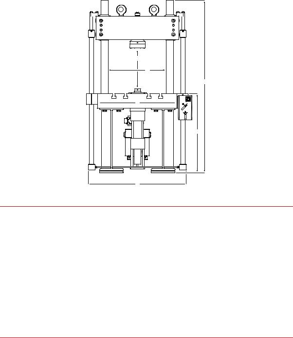
322 Basic Specifications
a
b
c
e
d
f
Fatigue Ratings, Dimensions, and Weight
|
MODEL 322.21 |
MODEL 322.31 |
MODEL 322.41 |
|
|
|
|
Load unit fatigue rating |
100 kN (22 kip) |
250 kN (55 kip) |
500 kN (110 kip) |
|
|
|
|
A maximum specimen/grip clearance* |
1270 mm (50.0 in) |
1575 mm (62.0 in) |
2057 mm (81.0 in) |
B width between columns |
533 mm (21.0 in) |
635 mm (25.0 in) |
762 mm (30.0 in) |
|
|
|
|
C height — with standard columns† |
2489 mm (98 in) |
3010 mm (118.5 in) |
3677 mm (144.75 in) |
D table height |
838 mm (33.0 in) |
864 mm (34.0 in) |
984 mm (38.7 in) |
|
|
|
|
E table width — side-to-side, without lifts |
711 mm (28.0 in) |
864 mm (34.0 in) |
1067 mm (42.0 in) |
|
|
|
|
F width — side-to-side, with lifts‡ |
864 mm (34.0 in) |
1016 mm (40.0 in) |
1219 mm (48.0 in) |
Depth — front-to-back (not shown)‡ |
1000 mm (40.0 in) |
1000 mm (40.0 in) |
1500 mm (60.0 in) |
Weight§ |
1370 kg (3000 lb) |
2050 kg (4500 lb) |
3870 kg (8500 lb) |
* With a standard Series 661 Force Transducer and a fully retracted 150 mm (6 in) displacement actuator.
† With a table mounted actuator.
‡ On standard length tables.The control module’s position can increase the table’s width and depth.
§Typical maximum weight with hydraulic locks, hydraulic lifts, and a standard dimension platen. Does not include the weight of grips or other accessories.
Series 322 Load Unit |
Introduction |
17 |


 a
a 

b 
 c
c
d e 


ANSI Standard B.5.1 T-Slot Dimension*
MODEL |
T-BOLT SIZE |
A |
B |
C |
D |
E |
|
|
|
|
|
|
|
332.21 |
0.75 in |
0.81 in |
1.21 in |
0.62 in |
0.59 in |
1.44 in |
|
|
|
|
|
|
|
322.31 |
1 in |
1.06 in |
1.82 in |
1.00 in |
0.82 in |
1.82 in |
|
|
|
|
|
|
|
322.41 |
1 in |
1.06 in |
1.82 in |
1.00 in |
0.82 in |
1.82 in |
*Minimum tolerances.
DIN Standard 650 T-Slot Dimension*
MODEL |
T-BOLT SIZE |
A |
B |
C |
D |
E |
|
|
|
|
|
|
|
332.21 |
22 mm |
22 mm |
38 mm |
22 mm |
16 mm |
37 mm |
|
|
|
|
|
|
|
322.31 |
28 mm |
28 mm |
48 mm |
28 mm |
20 mm |
46 mm |
|
|
|
|
|
|
|
322.41 |
28 mm |
28 mm |
48 mm |
28 mm |
20 mm |
46 mm |
*Minimum tolerances.
18 |
Introduction |
Series 322 Load Unit |

d
e
h
f
g
a
c
b
T-slot Platen Dimensions — U.S. Customary
T-slot Platen Dimensions
MODEL |
A |
B* |
C |
D |
E† |
F |
G |
H |
332.21 |
711 mm |
1000 mm |
355.6 mm |
508.0 mm |
127.0 mm |
228.6 mm |
101.6 mm |
127.0 mm |
|
(28.0 in) |
(40.0 in) |
(14.0 in) |
(20.0 in) |
(5.0 in) |
(9.0 in) |
(4.0 in) |
(5.0 in) |
|
|
|
|
|
|
|
|
|
322.31 |
864 mm |
1000 mm |
431.8 mm |
508.0 mm |
152.4 mm |
254.0 mm |
127.0 mm |
127.0 mm |
|
(34.0 in) |
(40.0 in) |
(17.0 in) |
(20.0 in) |
(6.0 in) |
(10.0 in) |
(5.0 in) |
(5.0 in) |
|
|
|
|
|
|
|
|
|
322.41 |
1067 mm |
1500 mm |
533.4 mm |
762.0 mm |
304.8 mm |
304.8 mm |
177.8 mm |
127.0 mm |
|
(42.0 in) |
(60.0 in) |
(21.0 in) |
(30.0 in) |
(12.0 in) |
(12.0 in) |
(7.0 in) |
(5.0 in) |
*Larger tables available.
† Distance to optional second actuator mounting position.
Series 322 Load Unit |
Introduction |
19 |

c |
d |
b |
a |
Deflections and Spring Rates
|
322.21 |
322.31 |
322.41 |
|
|
|
|
Deflections* |
100 kN (22 kip) |
250 kN (55 kip) |
500 kN (110 kip) |
A-B base |
0.15 mm (0.006 in) |
0.18 mm (0.007 in) |
0.20 mm (0.008 in) |
|
|
|
|
B-C columns |
0.10 mm (0.004 in) |
0.20 mm (0.006 in) |
0.20 mm (0.008 in) |
|
|
|
|
C-D crosshead |
0.13 mm (0.005 in) |
0.20 mm (0.010 in) |
0.25 mm (0.10 in) |
|
|
|
|
A-D overall frame |
0.38 mm (.015 in) |
0.53 mm (0.021 in) |
0.66 mm (0.026 in) |
|
|
|
|
Spring rates* |
2.6 x 10⁸ N/m |
4.6 x 10⁸ N/m |
7.4 x 10⁸ N/m |
|
(1.5 x 10⁶ lb/in) |
(2.6 x 10⁶ lb/in) |
(4.2 x 10⁶ lb/in) |
*Determined at each load unit’s full fatigue rating with its crosshead raised 50 in (1270 mm) above the T-slot table.
Deflection rates can vary 20%, depending on the type of actuator and force transducer you use.
For the most accurate high frequency test results, use a Load Unit with a fatigue rating that is larger than its actuator’s force rating. (A 322.31 Load Unit with a 55 kip fatigue rating and a 22 kip actuator will be stiffer than a 322.21 Load Unit with a 22 kip fatigue rating and 22 kip actuator.)
20 |
Introduction |
Series 322 Load Unit |
Series 322 Load Unit |
Introduction |
21 |

Series 661 Force Transducer: Specifications
The force transducer used with this system is a Series 661 Force Transducer. The following are the specifications for the force transducers.
PARAMETER |
SPECIFICATION |
|
|
Maximum excitation voltage |
15 V DC |
|
|
Bridge resistance |
350 ¾ |
|
|
Maximum crosstalk |
1.0% of full scale torsional to load |
|
|
Hysteresis |
0.08% of full scale (250 N–2.5 kN) |
|
0.05% of full scale (5 kN–50 kN) |
|
0.15% of full scale (100 kN–500 kN) |
|
0.20% of full scale (1000 kN) |
|
|
Nonlinearity |
0.08% of full scale |
|
0.15% of full scale for Models 661.22/.23/.31 |
|
|
Temperature |
0.004% of reading/°C (0.002%/°F) |
Usable range |
-54°C (-65°F) to +121°C (+250°F) |
Compensated range |
+21°C (+70°F) to +77°C (+170°F) |
Sensitivity |
0.0036% of full scale/°C |
|
(0.0020% of full scale/°F) |
|
|
Output |
2 mV/V at full-scale load |
|
|
Connector |
PT02ER-10-6P |
|
|
MODEL |
LOAD CAPACITY |
THREAD SIZE* |
WEIGHT |
661.11-01 |
250 N |
M6 x 1.0 mm x 6.3 mm |
0.45 kg |
|
(50 lbf) |
(1/4 - 28 UNF x 0.25 in |
(1 lb) |
|
|
|
|
661.11-02 |
500 N |
M6 x 1.0 mm x 6.3 mm |
0.45 kg |
|
(100 lbf) |
(1/4 - 28 UNF x 0.5 in |
(1 lb) |
|
|
|
|
661.18-01 |
1 kN |
M12 x 1.25 mm x 25.4 mm |
2.27 kg |
|
(220 lbf) |
(1/2 - 20 UNF x 1.0 in) |
(5 lb) |
|
|
|
|
661.18-02 |
2.5 kN |
M12 x 1.25 mm x 25.4 mm |
2.27 kg |
|
(550 lbf) |
(1/2 - 20 UNF x 1.0 in) |
(5 lb) |
|
|
|
|
661.19-01 |
5 kN |
M12 x 1.25 mm x 25.4 mm |
3.07 kg |
|
(550 lbf) |
(1/2 - 20 UNF x 1.0 in) |
(6.75 lb) |
|
|
|
|
661.19-02 |
10 kN |
M12 x 1.25 mm x 25.4 mm |
3.07 kg |
|
(2.2 kip) |
(1/2 - 20 UNF x 1.0 in) |
(6.75 lb) |
|
|
|
|
661.19-03 |
15 kN |
M12 x 1.25 mm x 25.4 mm |
3.07 kg |
|
(3.3 kip) |
(1/2 - 20 UNF x 1.0 in) |
(6.75 lb) |
|
|
|
|
661.19-04 |
25 kN |
M12 x 1.25 mm x 25.4 mm |
3.07 kg |
|
(5.5 kip) |
(1/2 - 20 UNF x 1.0 in) |
(6.75 lb) |
|
|
|
|
22 |
Introduction |
Series 322 Load Unit |

MODEL |
LOAD CAPACITY |
THREAD SIZE* |
WEIGHT |
661.20-01 |
25 kN |
M27 x 2.0 mm x 31.7 mm |
9.75 kg |
|
(5.5 kip) |
(1 - 14 UNS-3B x 1.25 in) |
(21.5 lb) |
|
|
|
|
661.20-02 |
50 kN |
M27 x 2.0 mm x 31.7 mm |
9.75 kg |
|
(11 kip) |
(1 - 14 UNS-3B x 1.25 in) |
(21.5 lb) |
|
|
|
|
661.20-03 |
100 kN |
M27 x 2.0 mm x 31.7 mm |
9.75 kg |
|
(2.2 kip) |
(1 - 14 UNS-3B x 1.25 in) |
(21.5 lb) |
|
|
|
|
661.22-01 |
250 kN |
M36 x 2.0 mm |
13.2 kg |
|
(3.3 kip) |
(1 1/2 - 12 UNC-2B) |
(29 lb) |
|
|
|
|
661.23-01 |
500 kN |
M52 x 2.0 mm x 48.3 mm |
16 kg |
|
(5.5 kip) |
(2.0 - 12 UN-2B x 1.9 in) |
(35.3 lb) |
|
|
|
|
661.31-01 |
1000 kN |
M76 x 1.75 mm x 28.4 mm |
49.9 kg |
|
(220 kip) |
(2.0 - 12 UN-2B x 1.35 in) |
(110 lb) |
*The thread sizes are available with either coarse or fine threads.
Dimensions The following dimensions are rounded off to the nearest millimeter or eight-inch.
|
|
|
C |
A |
|
||
|
|||
|
|
|
|
E
D
 B
B 
MODEL |
A |
B* |
C |
D* |
E |
661.11-01 |
70 mm |
18 mm |
7 mm |
38 mm |
61 mm |
|
(2–3/4 in) |
(3/4 in) |
(1/4 in) |
(1–1/5 in) |
(2–3/8 in |
|
|
|
|
|
|
661.18-01 |
105 mm |
32 mm |
7 mm |
67 mm |
64 mm |
|
(4–1/4 in) |
(1–1/4 in) |
(1/4 in) |
(2–5/8 in) |
(2–1/5 in) |
|
|
|
|
|
|
661.19-01 |
105 mm |
32 mm |
7 mm |
67 mm |
64 mm |
|
(4–1/4 in) |
(1–1/4 in) |
(1/4 in) |
(2-5/8 in) |
(2–1/5 in) |
|
|
|
|
|
|
661.20-01 |
154 mm |
57 mm |
10 mm |
95 mm |
89 mm |
|
(6 in) |
(2–1/4 in) |
(3/8 in) |
(3–3/4n) |
(3–1/2 in) |
|
|
|
|
|
|
661.22-01 |
114 mm |
92 mm |
1 mm |
203 mm |
74 mm |
|
(4–1/2 in) |
(3–5/8 in) |
(>1/4 in) |
(8 in) |
(2–7/8 in) |
|
|
|
|
|
|
661.23-01 |
152 mm |
140 mm |
N/A |
203 mm |
86 mm |
|
(6 in) |
(5–1/5 in) |
|
(8 in) |
(3–3/8 in) |
|
|
|
|
|
|
661.31-01 |
222 mm |
203 mm |
N/A |
305 mm |
124 mm |
|
(8–3/4 in) |
(8 in) |
|
(12 in) |
(4–7/8 in) |
*This dimension applies to both ends
Series 322 Load Unit |
Introduction |
23 |
24 |
Introduction |
Series 322 Load Unit |

Safety
General Safety Practices
This section provides information about safety issues that pertain to servohydraulic systems in general. These issues include statements to the intended use and foreseeable misuse of the system, the hazard zone, definition for the graphical hazard labeling that is affixed to your product, and other (more general) safety information that relates to the high-pressure and highperformance characteristics of MTS servohydraulic systems.
MTS test systems are designed to generate motions and forces and impart these motions and forces into a test specimen.
When you prepare to operate the system and during system operation, ensure the following:
•Do not use or allow personnel to operate the system who are not experienced, trained, or educated in the inherent dangers associated with high-performance servo hydraulics and who are not experienced, trained, or educated with regard to the intended operation as it applies to this test system.
•Do not disable safety components or features (including limit detectors, light curtains, or proximity switches/detectors).
•Do not attempt to operate the system without appropriate personal safety gear (for example, hearing, hand, and eye protection).
•Do not apply energy levels that exceed the maximum energies and velocities for the system design. Refer to the system specifications.
•Do not test a specimen that exceeds the minimum (if applicable) or maximum allowable mass. Refer to the system specifications.
•Do not use specimens that are combustible, flammable, pressurized, or explosive.
•Do not use humans as specimens or allow humans to ride in or on the test specimen or the test system for any purpose unless the system is man-rated and all associated safety conditions are strictly enforced.
•Do not modify the system or replace system components using parts that are not MTS component parts or effect repairs using parts or components that are not manufactured to MTS specifications.
•Do not operate the system in an explosive atmosphere.
•Do not use the system in a test area where uncontrolled access to the test system is allowed when the system is in operation
•Do not operate the system unless an interlock is installed to monitor supply pressure into the HSM and initiate a system interlock if a low or no pressure event occurs.
Series 322 Load Unit |
Safety |
25 |
If you have system related responsibilities (that is, if you are an operator, service engineer, or maintenance person), you should study safety information carefully before you attempt to perform any test system procedure.
You should receive training on this system or a similar system to ensure a thorough knowledge of your equipment and the safety issues that are associated with its use. In addition, you should gain an understanding of system functions by studying the other manuals supplied with your test system. Contact MTS for information about the content and dates of training classes that are offered.
It is very important that you study the following safety information to ensure that your facility procedures and the system’s operating environment do not contribute to or result in a hazardous situation. Remember, you cannot eliminate all the hazards associated with this system, so you must learn and remain aware of the hazards that apply to your system at all times. Use these safety guidelines to help learn and identify hazards so that you can establish appropriate training and operating procedures and acquire appropriate safety equipment (such as gloves, goggles, and hearing protection).
Each test system operates within a unique environment which includes the following known variables:
•Facility variables (facility variables include the structure, atmosphere, and utilities)
•Unauthorized customer modifications to the equipment
•Operator experience and specialization
•Test specimens
Because of these variables (and the possibility of others), your system can operate under unforeseen circumstances that can result in an operating environment with unknown hazards.
Improper installation, operation, or maintenance of your system can result in hazardous conditions that can cause death, personal injury, or damage to the equipment or to the specimen. Common sense and a thorough knowledge of the system’s operating capabilities can help to determine an appropriate and safe approach to its operation.
Safety Practices Before System Operation
Before you apply hydraulic power to the test system, review and complete all of the safety practices that are applicable to your system. The goal, by doing this, is to improve the safety awareness of all personnel involved with the system and to maintain, through visual inspections, the integrity of specific system components.
Read all manuals Study the contents of this manual and the other manuals provided with your system before attempting to perform any system function for the first time. Procedures that seem relatively simple or intuitively obvious can require a complete understanding of system operation to avoid unsafe or dangerous situations.
26 |
Safety |
Series 322 Load Unit |
Locate and read hazard placards/labels
Locate Lockout/tagout
points
Know facility safe procedures
Locate Emergency
Stop buttons
Know controls
Have first aid available
Know potential crush and pinch points
Be aware of component movement with hydraulics off
Know electrical hazards
Find, read, and follow the hazard placard instructions located on the equipment. These placards are placed strategically on the equipment to call attention to areas such as known crush points and electrical voltage hazards.
Know where the lockout/tagout point is for all of the supply energies associated with your system. This includes the hydraulic, pneumatic, electric, and water supplies (as appropriate) for your system to ensure that the system is isolated from these energies when required.
Most facilities have internal procedures and rules regarding safe practices within the facility. Be aware of these safe practices and incorporate them into your daily operation of the system.
Know the location of all the system Emergency Stop buttons so that you can stop the system quickly in an emergency. Ensure that an Emergency Stop button is located within 2 meters (6 feet) of the operator at all times.
Before you operate the system for the first time, make a trial run through the operating procedures with the power off. Locate all hardware and software controls and know what their functions are and what adjustments they require. If any control function or operating adjustment is not clear, review the applicable information until you understand it thoroughly.
Accidents can happen even when you are careful. Arrange your operator schedules so that a properly trained person is always close by to render first aid. In addition, ensure that local emergency contact information is posted clearly and in sight of the system operator.
Be aware of potential crush and pinch points on your system and keep personnel and equipment clear of these areas.
Remember, when hydraulic power is interrupted on a servohydraulic system, it is likely that stored accumulator pressure will persist for some time within the system. In addition, it is likely that as stored energy dissipates, gravity will cause portions of the system to move.
The crosshead can slowly drift down the columns if the locks are turned off and when hydraulic pressure is turned off. The crosshead can damage any test fixtures, grips, and specimen in its path. Unlock the crosshead only to reposition it. Always lock the crosshead after you have repositioned it and never leave the crosshead unlocked.
The actuator rod can also drift down when hydraulics are turned off hitting anything in its path. This uncommanded movement is because of oil movement between the pressure/return ports and oil blow by across the piston hub. Be aware that this can happen and clear the area around the actuator rod when hydraulics are turned off.
When the system electrical power is turned on, minimize the potential for electrical shock hazards. Wear clothing and use tools that are properly insulated for electrical work. Avoid contact with exposed wiring or switch contacts.
Whenever possible, turn off electrical power when you work on or in proximity to any electrical system component. Observe the same precautions as those given for any other high-voltage machinery.
Series 322 Load Unit |
Safety |
27 |
Keep bystanders safely away
Wear proper clothing
Remove flammable fluids
Know compressed gas hazards
Keep bystanders at a safe distance from all equipment. Never allow bystanders to touch specimens or equipment while the test is running.
Do not wear neckties, shop aprons, loose clothing or jewelry, or long hair that could get caught in equipment and result in an injury. Remove loose clothing or jewelry and restrain long hair.
Remove flammable fluids from their containers or from components before you install the container or component. If desired, you can replace the flammable fluid with a non-flammable fluid to maintain the proper proportion of weight and balance.
Most servohydraulic systems contain accumulators that require a high-pressure gas precharge (pressures that exceed 138 bar [2000 psi]). In addition, some systems can contain devices, such as static supports, that are pneumatically operated. High-pressure devices are potentially dangerous because a great amount of energy is available in the event of an uncontrolled expansion or rupture.
28 |
Safety |
Series 322 Load Unit |
Check bolt ratings and torques
Observe the following safety practices when you work with high-pressure air or gases:
•When you charge an accumulator, follow all the charging instructions provided in the appropriate product information manuals. When precharging accumulators, properly identify the type of gas to be used and the type of accumulator to be precharged.
Use only dry-pumped nitrogen to precharge nitrogen-charged accumulators. (Dry-pumped nitrogen can also be labeled “oil pumped” or “dry water pumped.”) Do not use compressed air or oxygen for precharging: the temperature increase caused by rapid gas compression can result in highly explosive conditions when hydraulic fluid is in the presence of oxygen or compressed air.
•Always follow the recommended bleeding procedures before you remove or disassemble components that contain pressurized gas. When you bleed a gas or remove a fitting, hose, or component that contains a gas, remember that many gases cannot support life. Therefore, as the ratio of released gas to oxygen increases, so does the potential for suffocation.
•Wear appropriate safety devices to protect your hearing. Escaping air or gas can create a noise level that can damage your hearing.
•Ensure that all pressurized air or gas is bled out of a pneumatic or gascharged device before you start to disassemble it. A thorough understanding of the assembly and its pressurized areas is necessary before you undertake any maintenance. Refer to the appropriate product information for the correct bleeding procedure.
It might not be obvious or intuitive which bolts or fittings are used to restrain a pressurized area. On some assemblies, you must remove a cover plate to gain access to the structural bolts. Sometimes, to protect you from a rapid release of trapped gases, a small port is exposed when you remove this cover plate. Exposing this port ensures that the gas precharge is fully bled before disassembly. However, this is not the recommended procedure for bleeding a pneumatic or gas-charged device, because it can expose you to the dangers of escaping compressed gas and particulates that are expelled from the chamber or around the seals. Do not assume that cover plates and ports are installed in all the critical locations.
Consult MTS when in doubt about the safety or reliability of any system-related procedure or modification that involves devices that contain any type of compressed gas.
To ensure a reliable product, fasteners (such as bolts and tie rods) used in MTSmanufactured systems are torqued to specific requirements. If a fastener is loosened or the configuration of a component within the system is modified, refer to the system and component assembly drawings (located on the System Documentation CD) to determine the correct fastener, fastener rating, and torque. Overtorquing or undertorquing a fastener can create a hazardous situation due to the high forces and pressures present in MTS test systems.
Series 322 Load Unit |
Safety |
29 |
Loading...