


 Loading...
m
be certain.
Series 505 SilentFlo™ Hydraulic Power Unit
Product Information
Model 505.60
Model 505.90
Model 505.120
Model 505.150
Model 505.180
100-006-453 U

Copyright information Trademark information
Publication information
© 1999–2010 MTS Systems Corporation. All rights reserved.
MTS and SilentFlo are registered trademarks of MTS Systems Corporation within the United States. These trademarks may be protected in other countries.
DTE is a registered trademark of Exxon Mobil Corporation.
Tellus is a registered trademark of Shell Oil Corporation.
Synasol is a registered trademark of Union Carbide Corporation.
Molykote is a registered trademark of Dow Chemical Corporation.
MANUAL PART NUMBER |
PUBLICATION DATE |
|
|
100-006-453 A |
October 1999 |
|
|
100-006-453 B |
January 2000 |
|
|
100-006-453 C |
September 2000 |
|
|
100-006-453 D |
January 2001 |
|
|
100-006-453 E |
April 2001 |
|
|
100-006-453 F |
September 2001 |
|
|
100-006-453 G |
January 2002 |
|
|
100-006-453 H |
July 2002 |
|
|
100-006-453 I |
June 2003 |
|
|
100-006-453 J |
May 2004 |
|
|
100-006-453 K |
September 2004 |
|
|
100-006-453 L |
August 2005 |
|
|
100-006-453 M |
June 2006 |
|
|
100-006-453 N |
August 2006 |
|
|
100-006-453 P |
September 2006 |
|
|
100-006-453 R |
February 2007 |
|
|
100-006-453 S |
March 2008 |
|
|
100-006-453 T |
April 2009 |
|
|
100-006-453 U |
March 2010 |
|
|

Contents
Technical Support |
7 |
|
|
|
|
|
|
||
|
How to Get Technical Support |
7 |
|
|
|
|
|||
|
Before You Contact MTS |
7 |
|
|
|
|
|
||
|
If You Contact MTS by Phone |
9 |
|
|
|
|
|||
|
Problem Submittal Form in MTS Manuals 10 |
|
|
||||||
Preface |
11 |
|
|
|
|
|
|
|
|
|
|
|
|
|
|
|
|
|
|
|
Before You Begin |
11 |
|
|
|
|
|
|
|
Conventions |
12 |
|
|
|
|
|
|
|
|
|
Documentation Conventions |
12 |
|
|
|
|
|||
Introduction |
15 |
|
|
|
|
|
|
|
|
|
|
|
|
|
|
|
|
|
|
|
EU Declarations |
15 |
|
|
|
|
|
|
|
|
Model 505.60 HPU Component Identification |
16 |
|
||||||
|
HPU Functional Description |
18 |
|
|
|
|
|||
|
Options Available for the HPU |
18 |
|
|
|
|
|||
|
Model 505.60/.90 HPU Hydraulic Schematic |
20 |
|
||||||
|
Model 505.120/.150/.180 HPU Hydraulic Schematic |
21 |
|||||||
|
Model 505.60 HPU Electrical Control |
22 |
|
|
|||||
|
Model 505.60/.90 Electrical Schematic |
23 |
|
|
|||||
|
Model 505.120/.150/.180 Electrical Schematic |
26 |
|
||||||
Specifications |
32 |
|
|
|
|
|
|
|
|
|
Model 505.60–505.180 HPU General Specifications |
32 |
|||||||
|
Model 505.60 HPU Specifications |
33 |
|
|
|
||||
|
Model 505.90 HPU Specifications |
34 |
|
|
|
||||
|
Model 505.120 HPU Specifications |
35 |
|
|
|||||
|
Model 505.150 HPU Specifications |
36 |
|
|
|||||
|
Model 505.180 HPU Specifications |
37 |
|
|
|||||
Safety |
39 |
|
|
|
|
|
|
|
|
|
|
||||||||
|
General Safety Practices: Hydraulic Power Units and Hydraulic Service Manifolds 39 |
||||||||
|
Hazard Placard Placement |
45 |
|
|
|
|
|||
Model 505.60 - 505.180 SilentFlo™ HPU |
Contents |
3 |

Installation |
47 |
|
|
|
|
|
|
Model 505.60—505.180 HPU Electrical, Hydraulic, and Water Connections 47 |
|||||||
Model 505.60 HPU Setup |
52 |
|
|
|
|
|
|
Testing Model 505.60 HPU Operation 56 |
|
|
|
||||
Precharging the Optional Surge Suppressor Accumulator |
59 |
||||||
Operation 63 |
|
|
|
|
|
|
|
|
|
|
|
|
|||
Model 505.60 HPU Startup Panel |
64 |
|
|
|
|||
Model 505.60 HPU Main Display |
66 |
|
|
|
|||
Model 505.60 HPU Data |
68 |
|
|
|
|
|
|
Model 505.60 HPU Status |
69 |
|
|
|
|
||
Model 505.60 HPU Setup |
70 |
|
|
|
|
|
|
ROD Setup 72 |
|
|
|
|
|
|
|
Operating the Model 505.60 HPU Locally or Remotely |
74 |
||||||
Recovering From an Interlock |
76 |
|
|
|
|||
Changing the Water Flow |
78 |
|
|
|
|
|
|
Resetting the Thermal Overloads |
79 |
|
|
|
|||
Adjusting the Model 505.60 Hydraulic Pressure |
81 |
|
|||||
Low/High Pressure Functionality |
83 |
|
|
|
|||
Setting Up Run-On-Demand |
85 |
|
|
|
|
||
Maintenance |
87 |
|
|
|
|
|
|
|
|
|
|
|
|||
Routine Maintenance Overview Checklist |
88 |
|
|
|
|||
Models 505.60/.90/.120/.150/.180 HPU Maintenance Schedule 90 |
|||||||
Checking the Hydraulic Fluid |
92 |
|
|
|
|||
Checking the Low Level/Temperature Detector |
93 |
|
|||||
Replacing the Return-line Filter |
94 |
|
|
|
|||
Clamp-Style Housing Filter Replacement 94 |
|
|
|
||||
Capscrew-Style Housing Filter Replacement |
96 |
|
|
||||
Replacing the Optional High-Pressure Filter |
97 |
|
|
||||
Sampling the Hydraulic Fluid |
99 |
|
|
|
|||
Replacing the Hydraulic Fluid |
101 |
|
|
|
|||
Inspecting the Heat Exchanger |
103 |
|
|
|
|||
Hydraulic Power Unit Maintenance and Service Logs 105 |
|||||||
|
|
|
|
|
|
|
|
8 Hours/Daily |
106 |
|
|
|
|
|
|
40 Hours/Weekly 107 |
|
|
|
|
|
|
|
4 |
Contents |
Model 505.60 - 505.180 SilentFlo™ HPU |
160 Hours/Biweekly 108
500 Hours 109
1000 Hours 110
2000 Hours 111
5000 Hours 112
10,000 Hours 113
Model 505.60 - 505.180 SilentFlo™ HPU |
Contents |
5 |
6 |
Contents |
Model 505.60 - 505.180 SilentFlo™ HPU |

How to Get Technical Support
Technical Support
How to Get Technical Support
Start with your manuals
Technical support methods
www.mts.com
Telephone
Fax
Outside the U.S.
The manuals supplied by MTS provide most of the information you need to use and maintain your equipment. If your equipment includes software, look for online help and README files that contain additional product information.
If you cannot find answers to your technical questions from these sources, you can use the Internet, e-mail, telephone, or fax to contact MTS for assistance.
MTS provides a full range of support services after your system is installed. If you have any questions about a system or product, contact Technical Support in one of the following ways.
The web site provides access to our technical support staff by means of an onlineform:
www.mts.com > Contact MTS > Service & Technical Support button
tech.support@mts.com
MTS Call Center 800-328-2255
Weekdays 7:00 A.M. to 5:00 P.M., Central Time
952-937-4515
Please include “Technical Support” in the subject line.
For technical support outside the United States, contact your local sales and service office. For a list of worldwide sales and service locations and contact information, use the Global MTS link at the MTS web site:
www.mts.com > Global MTS > (choose your region in the right-hand column) > (choose the location closest to you)
Before You Contact MTS
Know your site number and system number
MTS can help you more efficiently if you have the following information available when you contact us for support.
The site number contains your company number and identifies your equipment type (such as material testing or simulation). The number is typically written on a label on your equipment before the system leaves MTS. If you do not know your MTS site number, contact your sales engineer.
Example site number: 571167
When you have more than one MTS system, the system job number identifies your system. You can find your job number in your order paperwork.
Example system number: US1.42460
Model 505.60 - 505.180 SilentFlo™ HPU |
Technical Support |
7 |
Before You Contact MTS
Know information from |
If you have contacted MTS about this problem before, we can recall your file |
|
prior technical |
based on the: |
|
assistance |
• |
MTS notification number |
|
||
|
• |
Name of the person who helped you |
Identify the problem |
Describe the problem and know the answers to the following questions: |
|
|
• |
How long and how often has the problem occurred? |
|
• |
Can you reproduce the problem? |
|
• |
Were any hardware or software changes made to the system before the |
|
|
problem started? |
|
• |
What are the equipment model numbers? |
|
• |
What is the controller model (if applicable)? |
|
• |
What is the system configuration? |
Know relevant For a computer problem, have the following information available:
computer information
•Manufacturer’s name and model number
•Operating software type and service patch information
•Amount of system memory
•Amount of free space on the hard drive where the application resides
•Current status of hard-drive fragmentation
•Connection status to a corporate network
Know relevant For software application problems, have the following information available:
software information
•The software application’s name, version number, build number, and (if available) software patch number. This information can typically be found in the About selection in the Help menu.
•The names of other applications on your computer, such as:
–Anti-virus software
–Screen savers
–Keyboard enhancers
–Print spoolers
–Messaging applications
8 |
Technical Support |
Model 505.60 - 505.180 SilentFlo™ HPU |
If You Contact MTS by Phone
If You Contact MTS by Phone
A Call Center agent registers your call before connecting you with a technical support specialist. The agent asks you for your:
•Site number
•Name
•Company name
•Company address
•Phone number where you can be reached
Identify system type
Be prepared to troubleshoot
Write down relevant information
After you call
If your issue has a notification number, please provide that number. A new issue will be assigned a unique notification number.
To enable the Call Center agent to connect you with the most qualified technical support specialist available, identify your system as one of the following types:
•Electromechanical material test system
•Hydromechanical material test system
•Vehicle test system
•Vehicle component test system
•Aero test system
Prepare to perform troubleshooting while on the phone:
•Call from a telephone close to the system so that you can implement suggestions made over the phone.
•Have the original operating and application software media available.
•If you are not familiar with all aspects of the equipment operation, have an experienced user nearby to assist you.
In case Technical Support must call you:
•Verify the notification number.
•Record the name of the person who helped you.
•Write down any specific instructions.
MTS logs and tracks all calls to ensure that you receive assistance for your problem or request. If you have questions about the status of your problem or have additional information to report, please contact Technical Support again and provide your original notification number.
Model 505.60 - 505.180 SilentFlo™ HPU |
Technical Support |
9 |
Problem Submittal Form in MTS Manuals
Problem Submittal Form in MTS Manuals
Use the Problem Submittal Form to communicate problems with your software, hardware, manuals, or service that are not resolved to your satisfaction through the technical support process. The form includes check boxes that allow you to indicate the urgency of your problem and your expectation of an acceptable response time. We guarantee a timely response—your feedback is important to us.
Access the Problem Submittal Form:
•In the back of many MTS manuals (postage paid form to be mailed to MTS)
•www.mts.com > Contact Us > Problem Submittal Form button (electronic form to be e-mailed to MTS)
10 Technical Support |
Model 505.60 - 505.180 SilentFlo™ HPU |
Before You Begin
Preface
Before You Begin
Safety first!
Other MTS manuals
Before you use your MTS product or system, read and understand the Safety manual and any other safety information provided with your system. Improper installation, operation, or maintenance can result in hazardous conditions that can cause severe personal injury or death, or damage to your equipment and specimen. Again, read and understand the safety information provided with your system before you continue. It is very important that you remain aware of hazards that apply to your system.
In addition to this manual, you may receive additional manuals in paper or electronic form.
You may also receive an MTS System Documentation CD. It contains an electronic copy of the manuals that pertain to your test system, such as:
•Hydraulic and mechanical component manuals
•Assembly drawings
•Parts lists
•Operation manual
•Preventive maintenance manual
Controller and application software manuals are typically included on the software CD distribution disc(s).
Model 505.60 - 505.180 SilentFlo™ HPU |
Preface |
11 |

Conventions
Conventions
Documentation Conventions
The following paragraphs describe some of the conventions that are used in your
MTS manuals.
Hazard conventions Hazard notices may be embedded in this manual. These notices contain safety information that is specific to the activity to be performed. Hazard notices immediately precede the step or procedure that may lead to an associated hazard. Read all hazard notices carefully and follow all directions and recommendations. Three different levels of hazard notices may appear in your manuals. Following are examples of all three levels.
Note For general safety information, see the safety information provided with your system.

 DANGER
Danger notices indicate the presence of a hazard with a high level of risk which, if ignored, will result in death, severe personal injury, or substantial property damage.

 WARNING
Warning notices indicate the presence of a hazard with a medium level of risk which, if ignored, can result in death, severe personal injury, or substantial property damage.

 CAUTION
Notes
Special terms
Illustrations
Electronic manual conventions
Caution notices indicate the presence of a hazard with a low level of risk which, if ignored, could cause moderate or minor personal injury or equipment damage, or could endanger test integrity.
Notes provide additional information about operating your system or highlight easily overlooked items. For example:
Note Resources that are put back on the hardware lists show up at the end of the list.
The first occurrence of special terms is shown in italics.
Illustrations appear in this manual to clarify text. They are examples only and do not necessarily represent your actual system configuration, test application, or software.
This manual is available as an electronic document in the Portable Document File (PDF) format. It can be viewed on any computer that has Adobe Acrobat Reader installed.
12 Preface |
Model 505.60 - 505.180 SilentFlo™ HPU |
Documentation Conventions
Hypertext links The electronic document has many hypertext links displayed in a blue font. All blue words in the body text, along with all contents entries and index page numbers, are hypertext links. When you click a hypertext link, the application jumps to the corresponding topic.
Model 505.60 - 505.180 SilentFlo™ HPU |
Preface 13 |
Documentation Conventions
14 Preface |
Model 505.60 - 505.180 SilentFlo™ HPU |
EU Declarations
Introduction
Contents |
Model 505.60 |
HPU Component Identification |
16 |
|
|||
|
HPU Functional Description |
18 |
|
|
|
|
|
|
Options Available for the HPU |
18 |
|
|
|
|
|
|
Model 505.60/.90 HPU Hydraulic Schematic |
20 |
|
||||
|
Model 505.120/.150/.180 HPU Hydraulic Schematic |
21 |
|||||
|
Model 505.60 |
HPU Electrical Control |
22 |
|
|
||
|
Model 505.60/.90 Electrical Schematic |
23 |
|
|
|||
|
Model 505.120/.150/.180 Electrical Schematic |
26 |
|
||||
|
Model 505.60–505.180 HPU General Specifications |
32 |
|||||
|
Model 505.60 |
HPU Specifications |
33 |
|
|
|
|
|
Model 505.90 |
HPU Specifications |
34 |
|
|
|
|
|
Model 505.120 HPU Specifications |
35 |
|
|
|||
|
Model 505.150 HPU Specifications |
36 |
|
|
|||
|
Model 505.180 HPU Specifications |
37 |
|
|
|||
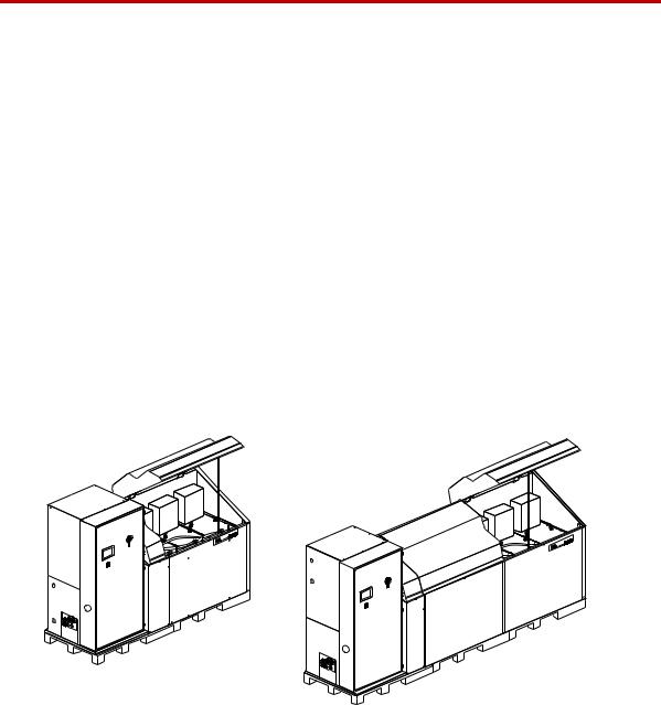
Models 505.60/.90 HPU
Models 505.120/.150/.180 HPU
EU Declarations
EC Declaration of
Conformity (Machinery
Directive 2006/42/EC
Annex II 1A)
If applicable, a Declaration of Conformity is supplied with the machinery; an example of the Declaration of Conformity is provided at the end of this manual.
Model 505.60 - 505.180 SilentFlo™ HPU |
Introduction 15 |
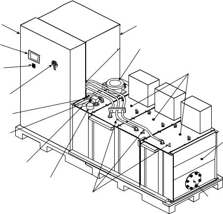
Model 505.60 HPU Component Identification
Model 505.60 HPU Component Identification
Main |
|
Electrical |
Heat Exchanger and |
Enclosure |
Manifold Enclosure |
User |
|
Interface |
Filter Assembly |
Panel |
|
Emergency |
Pump |
Stop Switch |
Assemblies |
Power
Disconnect
Switch
Level/Temperature
Switch
Level/Temperature |
|
|
Transducer |
|
Reservoir |
|
|
|
Fluid Level Gage |
|
|
|
Filler Cap |
|
|
Output |
Commoning |
|
Pressure |
|
|
Expansion Plate |
|
|
Controls |
|
|
|
Component Locations (505.90 Shown)
16 Introduction |
Model 505.60 - 505.180 SilentFlo™ HPU |
Model 505.60 HPU Component Identification
|
Component Descriptions |
|
|
Component |
Description |
|
|
Commoning Expansion |
Allows the HPU to be commoned with another HPU. |
Plate |
|
|
|
Electrical Enclosure |
Houses the HPU’s electrical and control components. The wye-delta starters |
|
for the Model 505.60/.90 HPUs are located in the electrical enclosure. The |
|
wye-delta starters for the Model 505.120/.150/.180 HPUs are located in the |
|
pump assemblies. The main power lines enter the electrical enclosure at its top. |
|
The power disconnect switch removes electrical power whenever the |
|
enclosure’s door is opened. |
|
|
Filler Cap |
Vents the hydraulic fluid reservoir. This is where you add hydraulic fluid. |
|
|
Filter |
Filters particles out of the hydraulic fluid as it is returned to the HPU. |
|
|
Fluid Level Gage |
Indicates the reservoir hydraulic fluid level. |
|
|
Heat Exchanger |
Cools the hydraulic fluid using a highly efficient, stainless steel oil-to-water |
|
heat exchanger. The heat exchanger removes most of the heat generated by the |
|
HPU. |
|
|
Level/Temperature |
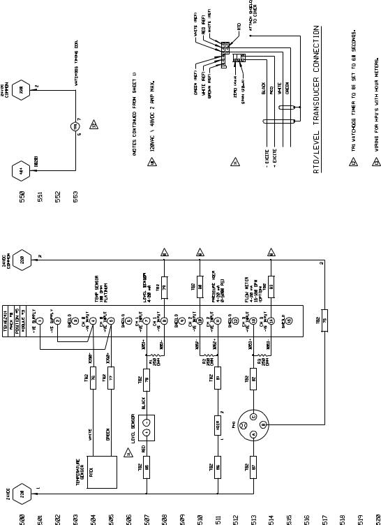
Senses the hydraulic fluid level and temperature, and produces an analog |
Transducer |
signal for display purposes. |
|
|
Low Level/Temperature |
Senses the hydraulic fluid level and temperature. Control interlocks |
Switch |
automatically shut the HPU down if the fluid level drops too low or the |
|
hydraulic fluid temperature rises above the sensor’s setting. |
|
|
Manifold |
Combines the output of the individual pumps to deliver the full output of the |
|
HPU through a single port. The manifold provides solenoid control of the high/ |
|
low pressure output from the individual pumps. It also contains relief valves |
|
for each pump circuit and a bypass circuit to maintain the hydraulic |
|
temperature during low flow conditions. |
|
|
Output Pressure Controls |
Sets the output pressure of each pump assembly. |
|
|
Power Disconnect Switch |
Disconnects the incoming power from the HPU. The switch is a lockable, |
|
mechanical latch. Power is removed whenever the door to the electrical |
|
enclosure is open. The switch will not allow the door to be opened when in the |
|
ON (|) position. Incoming power lines to the switch are live unless power is |
|
removed externally. |
|
|
Pump Assemblies |
Produces the pressurized hydraulic fluid for system use. Each pump assembly |
|
includes a motor, pump, and electrical enclosure for connecting with the main |
|
starter. |
|
|
Reservoir |
Holds the hydraulic fluid and houses the pump and motor. |
|
|
User Interface Panel |
Configures and controls the operation of the hydraulic power unit and indicates |
|
the current status of several sensors. |
|
|
Model 505.60 - 505.180 SilentFlo™ HPU |
Introduction 17 |
HPU Functional Description
HPU Functional Description
Pump assemblies
Manifold
Filtering
Heat exchanger
Pump assemblies draw hydraulic fluid from the reservoir and pressurize it to a maximum preset pressure. Each pump assembly contains a variable volume pump, a motor, and an electrical enclosure. Each pump assembly has a flow capacity that contributes to the total hydraulic flow capacity of the HPU.
The manifold combines the pressurized hydraulic output of the discrete pump assemblies, and provides the hydraulic connection to your hydraulic system. The manifold contains the high/low pressure solenoid valve and a nonadjustable relief valve. Check valves are located within the manifold to prevent pressurized hydraulic fluid from being forced back through the pumps.
The hydraulic power unit uses solenoid-operated valves to control when highpressure is available to the hydraulic circuit. Start/low/high control settings are selected at the operator interface on the electrical enclosure’s front panel.
The HPU is designed to start in low pressure to reduce the amperage needed for starting, which will extend the life of the pump and motor. When operating at this setting, low-pressure hydraulic fluid circulates back to the reservoir through the manifold. The direct fluid path back to the reservoir limits pressure and flow available out to the external hydraulic circuit. When high pressure is selected, the unit forces pressurized hydraulic fluid out to the hydraulic circuit.
As hydraulic fluid returns to the reservoir, it is filtered by a full flow element. This ensures that all hydraulic fluid is filtered, whether it travels out through the circuit or returns by way of the unit’s manifold under low pressure. Filter cleanliness is automatically monitored. A warning registered on the unit’s operator interface signals when the filter needs to be changed.
Hydraulic fluid temperature is maintained with a high–efficiency stainless steel heat exchanger that cools the fluid. A regulating valve monitors the temperature of the hydraulic fluid and adjusts the flow of water through the plates. The flow of cooling water regulates the temperature of the hydraulic fluid. If the hydraulic fluid temperature exceeds the maximum preset temperature, a switch opens and shuts down the HPU. When the HPU is shut off, the flow of water is automatically stopped by a shutoff solenoid valve.
Options Available for the HPU
Accumulator option
Run-on-demand option
Accumulators can be added to the hydraulic output lines to damp pressure line fluctuations. This option accommodates one pressure line accumulator.
The run-on-demand (ROD) option will turn individual pumps on and off as needed to accommodate the system’s demand for hydraulic fluid. The PLC monitors the fluid flow; when flow changes beyond preset limits for a preset time, a pump will be turned on or off as needed.
18 Introduction |
Model 505.60 - 505.180 SilentFlo™ HPU |
Options Available for the HPU
The ROD option allows the HPU to turn individual pump motors on and off as your system flow demand changes. A minimum flow reserve is maintained and pump usage is equalized by sequentially turning on pumps starting with the pump with the least amount of run time, and turning the pumps off in reverse order. The cycling of these pumps is controlled by a PLC that takes into account various system parameters such as system hydraulic fluid flow (both real time and trends), the number of pumps currently running, and user configurable on/off delay settings.
Model 505.60 - 505.180 SilentFlo™ HPU |
Introduction 19 |
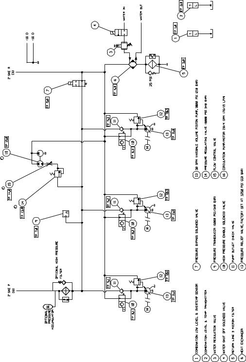
Model 505.60/.90 HPU Hydraulic Schematic
Model 505.60/.90 HPU Hydraulic Schematic
The hydraulic schematic shows the functional layout of HPU models with two or three pump assemblies (505.60/.90).
20 Introduction |
Model 505.60 - 505.180 SilentFlo™ HPU |
Model 505.120/.150/.180 HPU Hydraulic Schematic
Model 505.120/.150/.180 HPU Hydraulic Schematic
The hydraulic schematic shows the functional layout of HPU models with four to six pump assemblies (505.120/.150/.180).
Model 505.60 - 505.180 SilentFlo™ HPU |
Introduction |
21 |
Model 505.60 HPU Electrical Control
Model 505.60 HPU Electrical Control
The HPU can be controlled locally using the front panel controls, or remotely through a controller via the J1 connector. A PLC (programmable logic controller) manages the electrical systems within the HPU. The electrical system includes the following:
•A user interface panel that contains a touch screen to program preferences and operational settings. The screens on the user interface panel provide quick indication of the unit’s condition, including motors status, running time displays for each motor, hydraulic fluid level and temperature, and filter condition.
•Wye-delta starting reduces the initial current rush when the motor starters are engaged.
•Thermal overloads protect the individual HPU motors from excessive current draw.
•A latchable Emergency Stop button prevents inadvertent starts.
•Interlocks protect the HPU against low hydraulic fluid level, overtemperature, and dirty filters.
•A Reset button brings the unit back into operation after a fault has been detected and corrected.
•A dirty filter signal will not shut the unit down, but will prevent the unit from starting.
•The power disconnect switch on the door of the main electrical enclosure ensures that power is removed whenever the door is opened. This device is both an ETL and TÜV-certified, lockable, main-disconnect switch.
Note The electrical schematics for the HPU are located on the following pages. The difference between the Model 505.60/.90 and Model 505.120-180 is the number of pump assemblies.
22 Introduction |
Model 505.60 - 505.180 SilentFlo™ HPU |

Model 505.60/.90 Electrical Schematic
Model 505.60/.90 Electrical Schematic
The electrical schematic shows the electrical layout of the Model 505.60/.90
HPU.
Model 505.60 - 505.180 SilentFlo™ HPU |
Introduction |
23 |
Model 505.60/.90 Electrical Schematic
24 Introduction |
Model 505.60 - 505.180 SilentFlo™ HPU |
Model 505.60/.90 Electrical Schematic
Model 505.60 - 505.180 SilentFlo™ HPU |
Introduction 25 |
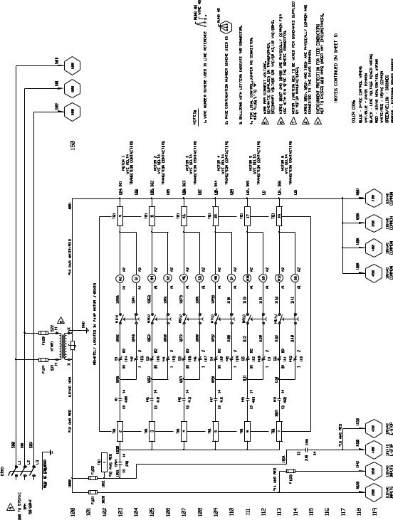
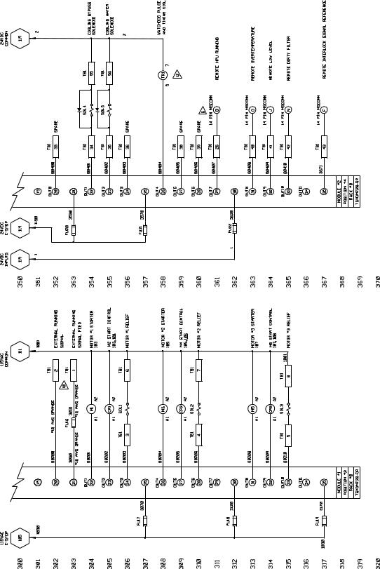
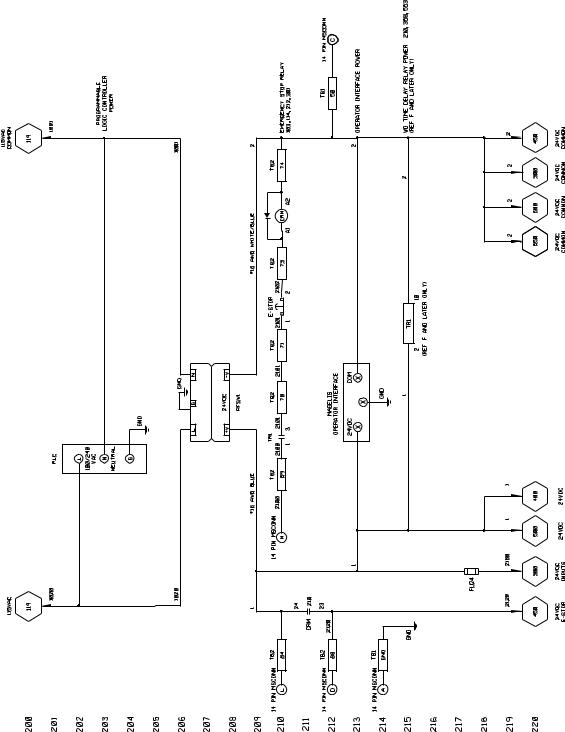
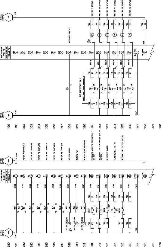
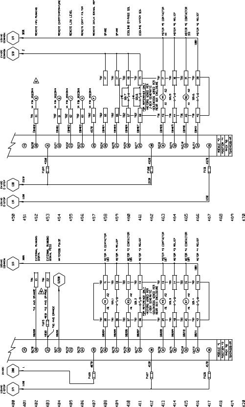
Model 505.120/.150/.180 Electrical Schematic
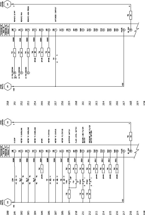
Model 505.120/.150/.180 Electrical Schematic
The electrical schematic shows the electrical layout of the Model 505.120/.150/
.180 HPU.
26 |
Introduction |
Model 505.60 - 505.180 SilentFlo™ HPU |
Model 505.120/.150/.180 Electrical Schematic
Model 505.60 - 505.180 SilentFlo™ HPU |
Introduction 27 |
Model 505.120/.150/.180 Electrical Schematic
28 Introduction |
Model 505.60 - 505.180 SilentFlo™ HPU |
Model 505.120/.150/.180 Electrical Schematic
Model 505.60 - 505.180 SilentFlo™ HPU |
Introduction 29 |
Model 505.120/.150/.180 Electrical Schematic
30 Introduction |
Model 505.60 - 505.180 SilentFlo™ HPU |
Loading...