


 Loading...
m
be certain.
SWIFT® 20 (Ultra) Sensor
Product Information
Spinning Wheel Integrated Force Transducer
For Small or High Performance Vehicles
100-037-800 L
Copyright information Trademark information
© 1999–2011 MTS Systems Corporation. All rights reserved.
MTS, SWIFT, TestStar, and TestWare are registered trademarks of MTS Systems Corporation within the United States. These trademarks may be protected in other countries.
Microsoft, Windows, Windows for Workgroups, Windows 95, and Windows NT are registered trademarks of Microsoft Corporation. Apple and Macintosh are registered trademarks of Apple Computer, Inc. UNIX is a registered trademark of The Open Group. LabVIEW is a registered trademark of National Instruments Corporation. All other trademarks or service marks are property of their respective owners.
Publication information |
Manual Part Number |
Publication Date |
|
|
|
|
151956-00 B |
February 1999 |
|
|
|
|
100-037-800 A |
12 June 2000 |
|
|
|
|
100-037-800 B |
17 July 2000 |
|
|
|
|
100-037-800 C |
9 May 2001 |
|
|
|
|
100-037-800 D |
December 2004 |
|
|
|
|
100-037-800 E |
February 2005 |
|
|
|
|
100-037-800 F |
April 2005 |
|
|
|
|
100-037-800 G |
May 2005 |
|
|
|
|
100-037-800 H |
October 2005 |
|
|
|
|
100-037-800 J |
January 2006 |
|
|
|
|
100-037-800 K |
November 2008 |
|
|
|
|
100-037-800 L |
December 2011 |
|
|
|

Contents
Technical Support |
7 |
|
|
|
|
|
|
|
|
|
|
|
|
|
|
||
How to Get Technical Support |
7 |
|
|
|
|
|
||
Before You Contact MTS 7 |
|
|
|
|
|
|
|
|
If You Contact MTS by Phone |
9 |
|
|
|
|
|
||
Problem Submittal Form in MTS Manuals |
10 |
|
|
|
||||
Preface 11 |
|
|
|
|
|
|
|
|
|
|
|
|
|
|
|
|
|
Before You Begin |
11 |
|
|
|
|
|
|
|
Conventions |
12 |
|
|
|
|
|
||
Documentation Conventions |
12 |
|
|
|
|
|
|
|
Hardware Overview |
15 |
|
|
|
|
|
|
|
|
|
|
|
|||||
Spinning Applications (Test Track) |
16 |
|
|
|||||
Non-spinning Applications (Simulation Lab) |
17 |
|
||||||
Construction |
18 |
|
|
|
|
|
||
Design Features |
22 |
|
|
|
|
|
||
Coordinate System |
23 |
|
|
|
|
|||
Specifications |
25 |
|
|
|
|
|
||
Calibration |
29 |
|
|
|
|
|
|
|
Low-Profile Transducer Interface |
31 |
|
|
|||||
Low-Profile TI Front Panel 34 |
|
|
|
|||||
Low-Profile TI Rear Panel |
41 |
|
|
|
||||
Induction Power Source |
42 |
|
|
|
||||
Low-Profile TI Jumpers |
43 |
|
|
|
||||
Interfacing with RPC |
44 |
|
|
|
|
|||
Software Utilities 45 |
|
|
|
|
|
|
|
|
|
|
|
|
|
|
|
||
Introduction |
46 |
|
|
|
|
|
||
TISTATUS - Low-Profile Transducer Interface Status |
47 |
|||||||
TIXFER - Low-Profile Transducer Interface Transfer |
48 |
|||||||
TISHUNT - Low-Profile Transducer Interface Shunt |
51 |
|||||||
Setting Up Shunt Calibration Reference Values |
55 |
|
||||||
TISETZERO – Low-Profile Transducer Interface Set Zero Method 56
SWIFT 20 Sensors |
Contents |
3 |

Error Messages |
57 |
|
|
|
|
|
|
|
|
||
Shunt Error Status 58 |
|
|
|
|
|
|
|
|
|||
Setting up the Low-Profile Transducer Interface |
59 |
|
|
||||||||
|
|
|
|
|
|
|
|
|
|||
Select a Zero Method |
60 |
|
|
|
|
|
|
|
|||
Calibration File Elements |
61 |
|
|
|
|
|
|||||
Upload the Calibration File |
64 |
|
|
|
|
|
|||||
Edit the Calibration File |
66 |
|
|
|
|
|
|
||||
Download the Calibration File |
70 |
|
|
|
|
||||||
Installing the Transducer |
73 |
|
|
|
|
|
|
|
|
|
|
|
|
||||||||||
Transducers Designed to Operate with a Low-Profile TI but Using a Mini TI |
73 |
||||||||||
Test Track Vehicle for Slip Ring Sensor 74 |
|
|
|
|
|||||||
Attaching SWIFT Components to the Wheel Assembly |
77 |
|
|||||||||
Attaching SWIFT and Wheel Assembly to the Vehicle |
80 |
|
|||||||||
Installing the Low-Profile Transducer Interface Electronics |
82 |
||||||||||
Setting up the SWIFT Sensor for Data Collection |
85 |
|
|
||||||||
Verifying the Quality of the Zero Procedure |
95 |
|
|
|
|||||||
Collecting Data |
98 |
|
|
|
|
|
|
|
|
||
Road Simulator |
100 |
|
|
|
|
|
|
|
|
||
Attaching SWIFT Components to the Fixturing |
102 |
|
|
||||||||
Zeroing the Low-Profile Transducer Interface 105 |
|
|
|||||||||
Communication Configurations |
106 |
|
|
|
|
||||||
Cable Configurations |
108 |
|
|
|
|
|
|
||||
SWIFT TI to PC Host (9-pin) 108 |
|
|
|
|
|
|
|
|
|||
SWIFT Low-Profile TI to PC Host (25-pin) |
108 |
|
|
|
|
|
|||||
SWIFT Low-Profile TI to SWIFT Low-Profile TI |
109 |
|
|
|
|
||||||
Termination Jumper |
110 |
|
|
|
|
|
|
|
|
|
|
Analyzing SWIFT Data |
111 |
|
|
|
|
|
|
|
|
|
|
|
|
|
|
|
|
|
|
|
|
|
|
The Data |
112 |
|
|
|
|
|
|
|
|
|
|
Fx Data (Longitudinal Force) |
113 |
|
|
|
|
||||||
Fz Data (Vertical Force) |
115 |
|
|
|
|
|
|||||
Mx Data (Overturning Moment) |
116 |
|
|
|
|
||||||
My Data (Brake Moment) |
119 |
|
|
|
|
|
|||||
Acceleration and Braking Events Example |
120 |
|
|
|
|||||||
Slalom Curve Driving Example |
122 |
|
|
|
|
||||||
4 |
Contents |
SWIFT 20 Sensors |

Maintenance 123
Transducer 124
Low-Profile Transducer Interface 125
Cables 126
Troubleshooting 127
Assembly Drawings |
141 |
|
|
|
|
Cable Drawings |
142 |
|
SWIFT 20A Mechanical Parts |
156 |
|
SWIFT 20T Mechanical Parts |
163 |
|
Common Parts |
170 |
|
SWIFT 20 Sensors |
Contents |
5 |
6 |
Contents |
SWIFT 20 Sensors |

Technical Support
How to Get Technical Support
Start with your manuals
Technical support methods
MTS web site
www.mts.com
Telephone
The manuals supplied by MTS provide most of the information you need to use and maintain your equipment. If your equipment includes MTS software, look for online help and README files that contain additional product information.
If you cannot find answers to your technical questions from these sources, you can use the internet, e-mail, telephone, or fax to contact MTS for assistance.
MTS provides a full range of support services after your system is installed. If you have any questions about a system or product, contact MTS in one of the following ways.
The MTS web site gives you access to our technical support staff by means of a Technical Support link:
www.mts.com > Contact MTS > Service & Technical Support
techsupport@mts.com
MTS Call Center 800-328-2255
Weekdays 7:00 A.M. to 5:00 P.M., Central Time
Fax 952-937-4515
Please include “Technical Support” in the subject line.
Technical support outside the U.S.
For technical support outside the United States, contact your local sales and service office. For a list of worldwide sales and service locations and contact information, use the Global MTS link at the MTS web site:
www.mts.com > Global MTS > (choose your region in the right-hand column) > (choose the location closest to you)
Before You Contact MTS
Know your site number and system number
MTS can help you more efficiently if you have the following information available when you contact us for support.
The site number contains your company number and identifies your equipment type (material testing, simulation, and so forth). The number is usually written on a label on your MTS equipment before the system leaves MTS. If you do not have or do not know your MTS site number, contact your MTS sales engineer.
Example site number: 571167
When you have more than one MTS system, the system job number identifies which system you are calling about. You can find your job number in the papers sent to you when you ordered your system.
Example system number: US1.42460
SWIFT 20 Sensors |
Technical Support |
7 |
Know information from prior technical assistance
Identify the problem
Know relevant computer information
Know relevant software information
If you have contacted MTS about this problem before, we can recall your file. You will need to tell us the:
•MTS notification number
•Name of the person who helped you
Describe the problem you are experiencing and know the answers to the following questions:
•How long and how often has the problem been occurring?
•Can you reproduce the problem?
•Were any hardware or software changes made to the system before the problem started?
•What are the model numbers of the suspect equipment?
•What model controller are you using (if applicable)?
•What test configuration are you using?
If you are experiencing a computer problem, have the following information available:
•Manufacturer’s name and model number
•Operating software type and service patch information
•Amount of system memory
•Amount of free space on the hard drive in which the application resides
•Current status of hard-drive fragmentation
•Connection status to a corporate network
For software application problems, have the following information available:
•The software application’s name, version number, build number, and if available, software patch number. This information is displayed briefly when you launch the application, and can typically be found in the “About” selection in the “Help” menu.
•It is also helpful if the names of other non-MTS applications that are running on your computer, such as anti-virus software, screen savers, keyboard enhancers, print spoolers, and so forth are known and available.
8 |
Technical Support |
SWIFT 20 Sensors |
If You Contact MTS by Phone
Identify system type
Be prepared to troubleshoot
Write down relevant information
After you call
Your call will be registered by a Call Center agent if you are calling within the United States or Canada. Before connecting you with a technical support specialist, the agent will ask you for your site number, name, company, company address, and the phone number where you can normally be reached.
If you are calling about an issue that has already been assigned a notification number, please provide that number. You will be assigned a unique notification number about any new issue.
To assist the Call Center agent with connecting you to the most qualified technical support specialist available, identify your system as one of the following types:
•Electromechanical materials test system
•Hydromechanical materials test system
•Vehicle test system
•Vehicle component test system
•Aero test system
Prepare yourself for troubleshooting while on the phone:
•Call from a telephone when you are close to the system so that you can try implementing suggestions made over the phone.
•Have the original operating and application software media available.
•If you are not familiar with all aspects of the equipment operation, have an experienced user nearby to assist you.
Prepare yourself in case we need to call you back:
•Remember to ask for the notification number.
•Record the name of the person who helped you.
•Write down any specific instructions to be followed, such as data recording or performance monitoring.
MTS logs and tracks all calls to ensure that you receive assistance and that action is taken regarding your problem or request. If you have questions about the status of your problem or have additional information to report, please contact MTS again and provide your original notification number.
SWIFT 20 Sensors |
Technical Support |
9 |
Problem Submittal Form in MTS Manuals
Use the Problem Submittal Form to communicate problems you are experiencing with your MTS software, hardware, manuals, or service which have not been resolved to your satisfaction through the technical support process. This form includes check boxes that allow you to indicate the urgency of your problem and your expectation of an acceptable response time. We guarantee a timely response—your feedback is important to us.
The Problem Submittal Form can be accessed:
•In the back of many MTS manuals (postage paid form to be mailed to MTS)
•www.mts.com > Contact Us > Problem Submittal Form (electronic form to be e-mailed to MTS)
10 Technical Support |
SWIFT 20 Sensors |
Preface
Before You Begin
Safety first!
Other MTS manuals
Before you attempt to use your MTS product or system, read and understand the Safety manual and any other safety information provided with your system. Improper installation, operation, or maintenance of MTS equipment in your test facility can result in hazardous conditions that can cause severe personal injury or death and damage to your equipment and specimen. Again, read and understand the safety information provided with your system before you continue. It is very important that you remain aware of hazards that apply to your system.
In addition to this manual, you may receive additional MTS manuals in paper or electronic form.
If you have purchased a test system, it may include an MTS System Documentation CD. This CD contains an electronic copy of the MTS manuals that pertain to your test system, including hydraulic and mechanical component manuals, assembly drawings and parts lists, and operation and preventive maintenance manuals. Controller and application software manuals are typically included on the software CD distribution disc(s).
SWIFT 20 Sensors |
Preface 11 |

Conventions
Conventions
Documentation Conventions
Hazard conventions
Notes
Special terms
Illustrations
Electronic manual conventions
The following paragraphs describe some of the conventions that are used in your MTS manuals.
As necessary, hazard notices may be embedded in this manual. These notices contain safety information that is specific to the task to be performed. Hazard notices immediately precede the step or procedure that may lead to an associated hazard. Read all hazard notices carefully and follow the directions that are given. Three different levels of hazard notices may appear in your manuals. Following are examples of all three levels.
Note For general safety information, see the safety information provided with your system.

 DANGER
Danger notices indicate the presence of a hazard with a high level of risk which, if ignored, will result in death, severe personal injury, or substantial property damage.

 WARNING
Warning notices indicate the presence of a hazard with a medium level of risk which, if ignored, can result in death, severe personal injury, or substantial property damage.

 CAUTION
Caution notices indicate the presence of a hazard with a low level of risk which, if ignored, could cause moderate or minor personal injury, equipment damage, or endanger test integrity.
Notes provide additional information about operating your system or highlight easily overlooked items. For example:
Note Resources that are put back on the hardware lists show up at the end of the list.
The first occurrence of special terms is shown in italics.
Illustrations appear in this manual to clarify text. It is important for you to be aware that these illustrations are examples only and do not necessarily represent your actual system configuration, test application, or software.
This manual is available as an electronic document in the Portable Document File (PDF) format. It can be viewed on any computer that has Adobe Acrobat Reader installed.
12 Preface |
SWIFT 20 Sensors |
Conventions
Hypertext links The electronic document has many hypertext links displayed in a blue font. All blue words in the body text, along with all contents entries and index page numbers, are hypertext links. When you click a hypertext link, the application jumps to the corresponding topic.
SWIFT 20 Sensors |
Preface 13 |
Conventions
14 Preface |
SWIFT 20 Sensors |
Hardware Overview
Important This manual includes information on the Low-Profile Transducer Interface (TI). For SWIFT transducers designed to operate with the newer Mini TI, there is a separate manual that documents the Mini TI, (MTS part number 100214316). For example information in this manual regarding shunt verification, zeroing procedures, or software utilities will pertain to the Low-Profile TI. If you have the Mini TI as a transducer interface, refer to its product manual for related information.
Overview The MTS Spinning Wheel Integrated Force Transducer (SWIFT®) is a lightweight, easy-to-use transducer that enables you to conduct faster, less expensive data acquisition and road simulation testing.
The transducer is designed for use both on the test track and in the test laboratory. It attaches to the test vehicle or an MTS Series 329 Road Simulator using an adapter and a modified wheel rim.
You can achieve excellent data correlation using the same transducer and vehicle on the test track and on a road simulator. It is available in various sizes and materials to fit various vehicle and loading requirements.
Data |
Test Track
Laboratory Simulation
S20-25
Contents |
Spinning Applications (Test Track) 16 |
||
|
Non-spinning Applications (Simulation Lab) 17 |
||
|
Construction |
18 |
|
|
Design Features |
22 |
|
|
Coordinate System |
23 |
|
|
Specifications |
25 |
|
Calibration 29
Low-Profile Transducer Interface 31
Low-Profile TI Front Panel |
34 |
Low-Profile TI Rear Panel |
41 |
Low-Profile TI Jumpers 43 |
|
Interfacing with RPC 44
SWIFT 20 Sensors |
Hardware Overview 15 |
Spinning Applications (Test Track)
Spinning Applications (Test Track)
The SWIFT sensor can be used for road load data acquisition (RLDA) applications:
•Durability
•Noise, Vibration and Harshness (NVH)
•Ride and Handling
•Tire Performance
The transducer is durable enough to withstand harsh road testing and data acquisition environments. The transducer is splash resistant and suitable for use in conditions where the test vehicle will encounter occasional standing or running water, or will be exposed to precipitation. However, it should not be submerged.
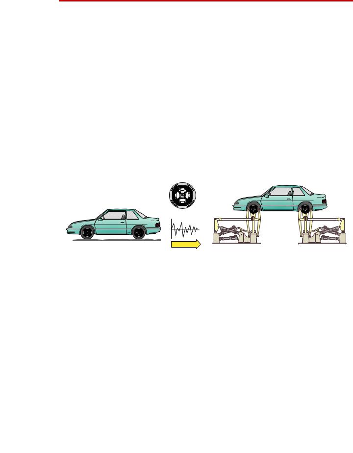
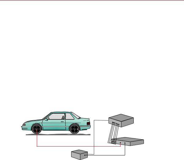
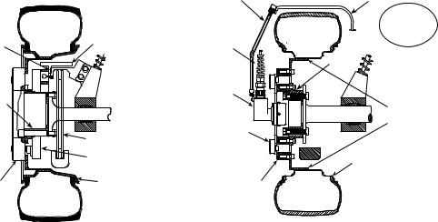
In a typical spinning application, the transducer is mounted on a modified rim of a tire on a test vehicle, as shown in the following figure. Data is transmitted from the spinning wheel to the Transducer Interface (TI) electronics via a slip ring mounted on the transducer.The TI, power supply, and data recorder can be located inside the vehicle or in the trunk.
Customer Supplied
|
|
Data Recorder |
|
Output |
|
|
Signals |
Transducer Interface |
|
|
(TI) |
Transducer Signals |
|
|
Customer Supplied |
|
|
12 Vdc Power Supply |
|
S20-26 |
Spinning Application (Test Track)
16 Hardware Overview |
SWIFT 20 Sensors |
Non-spinning Applications (Simulation Lab)
Non-spinning Applications (Simulation Lab)
The SWIFT sensor can be fully integrated into the simulation process, since it is an optimal feedback transducer for use with MTS Remote Parameter Control®
(RPC®) software. The transducer takes data at points where fixturing inputs are located rather than at traditional instrumentation points along the vehicle’s suspension. Using the SWIFT sensor saves you instrumentation time, and fewer iterations are required to achieve good simulation accuracy.
Measuring spindle loads allows engineers to generate generic road profiles. Generic road profiles are portable across various vehicle models, do not require new test track load measurements for each vehicle, and eliminate additional RLDA tasks.
Four of the six loads measured by the transducer directly correlate to the MTS Model 329 Road Simulator inputs: vertical force, longitudinal force, lateral force, and braking input.
The same transducers used to collect road data at the test track can be mounted directly in the wheel adapters of the MTS Model 329 Road Simulator. For durability testing, an aluminum SWIFT sensor can be used for iterations within the RPC process. The aluminum SWIFT sensor should then be removed for the durability cycles, to preserve its fatigue life. It can be replaced by an adapter plate, available from MTS, to duplicate the mass and center of gravity of the actual SWIFT sensor. If a SWIFT sensor is to be used during full durability tests, we suggest using the titanium model, which has a higher fatigue rating.
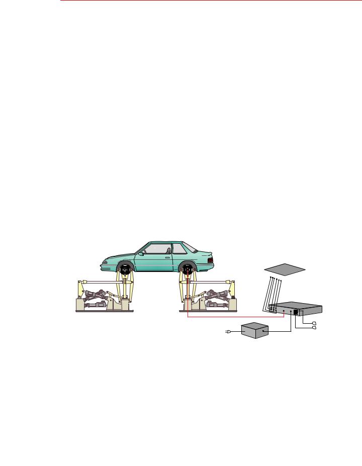
In a typical non-spinning application, a SWIFT sensor is mounted on a road simulation test fixture, as shown in the following figure.
Customer Supplied
Data Recorder
Output
Signals Transducer Interface
(TI)
Transducer Signals |
|
|
PC |
12 Vdc Power Supply |
Communication |
|
|
(with 4 connections) |
S20-27 |
Non-spinning Application (Laboratory Simulation)
SWIFT 20 Sensors |
Hardware Overview 17 |
Construction
Construction
The SWIFT sensor has one-piece construction for outstanding fatigue life, low hysteresis, and high stiffness. Its compact package has a minimal effect on inertia calculations, and a minimal dynamic effect on the test vehicle.
The transducer can be used for developing conventional durability tests on the MTS Model 329 Road Simulator. Normally, the transducer is replaced with an equivalent wheel adapter after the simulation drive signals are developed and prior to the start of the test.
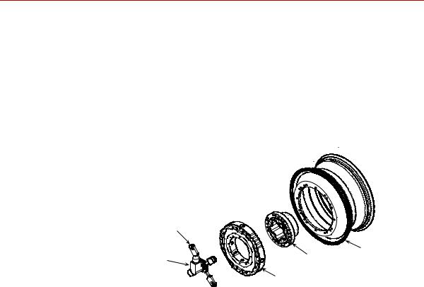
The SWIFT sensor includes several mechanical and electrical components.
Slip Ring
Bracket
Slip Ring |
Hub Adapter Modified Rim |
Encoder |
|
|
Transducer |
|
S20-57 |
Slip Ring Assembly
Transducer The transducer attaches directly to a modified wheel rim. On the test track, it spins with the wheel. It does not spin on a road simulator. The transducer is available in two materials: aluminum for spinning applications where the priority is on light weight, and titanium for non-spinning or higher force applications, where the priority is on durability.
The transducer’s unibody design means there are no multiple parts welded or screwed together.
The transducer has four beams with strain gages that measure six orthogonal outputs:
Fx—longitudinal force
Fy—lateral force
Fz—vertical force
Mx—overturning moment
My—acceleration and brake torque
Mz—steering moment
It has onboard conditioning and amplifiers to improve the signal-to-noise ratio.
18 Hardware Overview |
SWIFT 20 Sensors |
Construction
Hub adapter The hub adapter attaches to the inner diameter of the transducer, allowing you to place it at the original position of the spindle face of the vehicle. The hub adapter enables you to maintain the original position of the tire on the vehicle while the transducer is attached to the vehicle (the tire will not protrude from the vehicle).
|
Transducer |
|
Anti-rotate |
Interface |
|
Cable Bracket |
||
Device |
||
|
Hub |
Adapter |
Brake Rotor |
Telemetry Bearing |
with Hub Electronics |
Transducer |
Wheel Rim |
|
Anti-rotate Device |
Customer-supplied |
(Bend to fit vehicle) |
Attachment Bracket |
|
Attach to |
|
|
vehicle |
|
Transducer |
suspension |
|
|
||
Interface |
Hub |
|
Cable |
||
Adapter |
||
|
||
Slip |
|
|
Ring |
|
|
|
Customer-supplied |
|
|
Rim Adapter Flange |
|
Slip Ring |
|
|
Bracket |
|
|
|
Wheel Rim |
|
Transducer |
|
Telemetry Model |
Slip Ring Model |
S20-49 |
Components Set Up for Test Track
Slip ring bracket The slip ring bracket is used to attach the slip ring to the transducer. It has internal wiring that provides excitation power to the strain gage bridges and brings signals out from the transducer to the slip ring.
Encoder An encoder measures the angular position of the transducer. The SWIFT sensor uses an optical encoder that counts off “ticks” to measure the angular position as the wheel rotates. In applications using a slip ring, the integral encoder measures 2048 (512 plus quadrature) points per revolution (ppr) with a resolution of 0.18 degrees and an accuracy of 0.18 degrees.
Slip ring The slip ring allows you to output the transducer bridge signals and angular position to the TI. A transducer data cable attaches from the slip ring to the back panel of the TI. The slip ring is not typically used for non-spinning applications.
Anti-rotate device The anti-rotate device is attached to the stator portion of the slip ring and the vehicle’s suspension (or other non-rotating point). It is able to move up and down with the vehicle. Its primary function is to provide a fixed reference point for the optical encoder. Its secondary function is to prevent the cable from rotating with the wheel and becoming tangled or breaking.
The anti-rotate device is mainly used for road data collection. Although it can also be used for short periods of time on a road simulator. MTS does not recommend this use. Due to the extreme fatigue loading characteristics of durability testing on road simulators, we suggest that you either remove the slip ring assembly before installing the vehicle on a road simulator, or use it only for iteration passes, then promptly remove it.
SWIFT 20 Sensors |
Hardware Overview 19 |

Construction
The slip ring anti-rotate device should be configured such that no loading occurs to the slip ring throughout all loading and suspension travel. This means that when you attach the anti-rotate device to the vehicle, you must consider all possible motion of the suspension. The anti-rotate device should not bump against the wheel well at any time; any jarring of the anti-rotate arm will damage the slip ring. For steering axles, the anti-rotate bracket must be mounted to part of the unsprung suspension that steers with the tire, such as the brake caliper. For additional anti-rotate device mounting recommendations, refer to the Anti-Rotate Customer/User Assembly drawing at the back of this manual.
|
Cable Conduit |
|
|
|
Alignment Fixture |
Bracket |
Example of |
Tire must not |
Vehicle |
|
|
hit bracket when |
||
|
|
Anti-Rotate |
loaded or rotating. |
Fender |
|
|
Bracket Attached |
|
|
|
|
to Brake Caliper |
|
|
|
Example of |
|
|
Anti-Rotate |
|
Cable |
Bracket Attached |
|
to Strut |
||
Conduit |
||
|
||
Bracket |
|
Center line of Wheel
Anti-Rotate Bracket must be stiff (preferably steel or stiff aluminum tubing).
Suspension/ |
Unsprung Mass |

 Bracket must not
hit fender at extreme end of
suspension travel
Anti-Rotate
Assembly
Slip Ring
Assembly
Telemetry Model |
Slip Ring Model |
S20-55 |
|
Non-spinning connector housing or connector bracket
The non-spinning connector housing or the non-spinning connector bracket (both shown below) provide a connection between the SWIFT and the TI electronics for non-spinning use. Both assemblies incorporate rugged connectors suitable for durability testing. The non-spinning connector housing can also include an optional connector with built-in, tri-axial accelerometers.
|
|
Non-Spinning |
|
Connector Bracket |
|
Shunt A |
Shunt B |
|
|
Non-Spinning |
Spinning |
|
Cable Assembly |
Slip Ring |
Accelerometer |
Load |
Bracket |
|
||
(optional) |
|
|
|
S20-54 |
S20-58 |
|
|
|
|
Connector Housing |
Non-Spinning |
|
|
|
|
Connector Bracket |
|
20 Hardware Overview |
SWIFT 20 Sensors |
Construction
Transducer Interface The TI comes in two versions: a Low-Profile TI and the newer Mini TI.
(TI) Information on the Low-Profile TI can be found in this manual. Information on the Mini TI can be found in a separate product manual (MTS part number 100214316).
The Low-Profile TI conditions the power supply, and uses previously stored calibration values to convert the eight bridge outputs and the encoder signal to six non-rotating analog outputs (Fx, Fy, Fz, Mx, My, Mz) plus an angle output (or angular velocity with the Mini TI). The force and moment outputs have a value of 10 V full scale, unless a different full-scale output is requested by a customer. The angle output is a 0–5 V sawtooth output.
Low-profile TI
Mini TI
Additional Additional components that are supplied with your SWIFT sensor include shunt components and transducer data cables, TI power cable, a SWIFT Transducer Interface
Utilities disk, and the calibration file. MTS can also provide a 12 V DC power converter for use in the test laboratory.
SWIFT 20 Sensors |
Hardware Overview 21 |

Construction
Design Features
Flexure isolation
Thermal stability
Low hysteresis
Low noise
Low cross talk
Velocity information
The SWIFT sensor has a very stiff outer ring and flexured beam isolation which render it relatively insensitive to stiffness variations in matings with rims and road simulator fixtures.
Flexure isolation minimizes thermal expansion stresses. With flexure isolation, if the inner hub experiences thermal expansion the beams are allowed to expand out, resulting in lower compressive stress on the beams.
The entire sensor is machined from a solid, specially forged billet of high strength aluminum or titanium. The absence of bolted joints permits an efficient transfer of heat across the sensor structure, minimizing temperature differentials in the gaged area.
As mentioned earlier, flexure isolation allows thermal expansion with minimal stresses.
The transducer is designed to accommodate the high temperature environments that occur during severe driving and braking events. Individual temperature compensation of each strain gage bridge minimize temperature induced variations in accuracy. Since minimal electronics reside on the SWIFT sensor, it can easily tolerate high temperatures. The temperature rating for the SWIFT sensor is 125° C (257° F) at the spindle hub.
Temperature compensation is done on each bridge for better performance in transient or non-uniform temperature occurrences.
The SWIFT sensor has very low hysteresis, since the sensing structure is constructed with no bolted joints. Micro slippage in bolted joints contributes most of the hysteresis in highly stressed structures. Hysteresis errors due to micro-slip at joints can contribute to unresolvable compounding errors in coordinate transformation of the rotating sensor.
On-board amplification of the transducer bridges minimizes noise contribution prior to data transmission via low noise slip ring.
The advanced design of the SWIFT sensor means that it has very low cross talk. The alignment of the sensing element is precision machined. This alignment is critical to achieving minimum cross talk error between axes and minimum errors in coordinate transformation (from a rotating to a nonrotating coordinate system). Any small amount of cross talk present is compensated by the TI.
Angular position output is available from the TI when it is used in the spinning mode with the encoder. For the Low-Profile TI, this angular output can be used to calculate wheel velocity. In non-spinning applications, accelerometers can be integrated into the transducer connector housing.
The Mini TI has a user selectable angle or angular velocity output.
Note MTS does not supply any conditioning electronics for accelerometers. Ask your MTS consultant for more information about this option.
22 Hardware Overview |
SWIFT 20 Sensors |
Coordinate System
Coordinate System
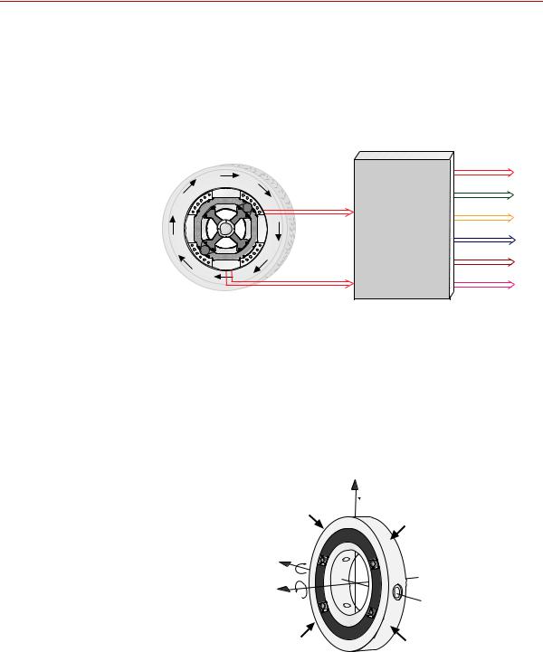
In the transducer, independent strain gage bridges measure forces and moments about three orthogonal axes. The signals are amplified to reduce the signal-to- noise ratio. An encoder signal indicates angular position, which is used to convert raw force and moment data from the rotating transducer to a vehiclebased coordinate system. The force and moment and encoder information is sent to the transducer interface (TI).
|
Output signals |
|
|
+ 10 Volts |
|
|
Fx |
|
Bridge |
Fy |
|
Outputs |
||
Transducer |
Fz |
|
Interface |
Mx |
|
|
||
|
My |
|
Angular |
Mz |
|
S20-06 |
||
Position |
||
|
The TI performs cross talk compensation and converts the rotating force and moment data to a vehicle coordinate system. The result is six forces and moments that are measured at the spindle: Fx, Fy, Fz, Mx, My, and Mz. A seventh (angle) output is available for tire uniformity information, angular position, or to determine wheel speed (depending on the data acquisition configuration).
The coordinate system shown below was originally loaded into the TI settings by
MTS. It uses the right-hand rule.
+Fz
 +Mz
+Mz
+Fx |
+Mx |
|
|
+Fy |
+My |
|
Forces acting on outer ring S20-07
The SWIFT coordinate system is transducer-based, with the origin located at the center of the transducer. The lateral offset of the transducer is illustrated in the reference drawings at the end of this manual. Positive loads are defined as applied to the outer ring of the transducer.
SWIFT 20 Sensors |
Hardware Overview 23 |
Coordinate System
The direction of positive forces follows the right hand rule:
•Vertical force (Fz) is positive up
•Lateral force (Fy) is positive out of the vehicle
•Longitudinal force (Fx) is positive fore or aft of the vehicle depending on which side of the vehicle the SWIFT is mounted
You can change to the MTS Model 329 Road Simulator convention (lateral load into the vehicle is always positive) or to any coordinate system by changing the polarities in the calibration file. For instructions on how to change the coordinate system polarities, see the chapter, “Setting up the Transducer Interface” in this manual or refer to “Transducer Interface Setup” in the Mini TI manual.
The Mini TI has the capability to offset the coordinate system. For example you can offset the coordinate system such that the coordinate system is at the center of the rim instead of the default coordinate system location at the center of the transducer. The Mini TI manual has additional information.
24 Hardware Overview |
SWIFT 20 Sensors |

Specifications
Specifications
SWIFT 20 Transducer Performance |
|
|
Parameter |
Specification |
|
Use |
|
|
SWIFT 20 A (aluminum) for |
low weight, high sensitivity |
|
SWIFT 20 T (titanium) for |
high fatigue life, durability |
|
|
|
|
Maximum usable rpm |
|
2,200 |
|
|
|
Maximum speed |
240 kph (150 mph) |
|
|
|
|
fits rim size (usable range) |
12–15 inch* |
|
Maximum hub bolt circle diameter |
4.5 inch (114.3 mm) |
|
accommodates M12 or 1/2 inch studs |
|
|
Input voltage required |
10–17 VDC |
|
|
|
|
Input power required per transducer |
30 W maximum (22 W typical) |
|
|
|
|
Output voltage ± full scale calibrated load |
±10 V † |
|
|
Aluminum |
Titanium |
SAE J328 rated load capacity |
4.3 kN (965 lbf) |
7.0 kN (1,580 lbf) |
Standard Maximum Calibrated Load Rating‡ |
|
|
Longitudinal force (Fx) |
±21 kN (±4,720 lbf) |
±30 kN (±6,745 lbf) |
Lateral force range (Fy) |
±16 kN (±3,595 lbf) |
±25 kN (±5,620 lbf) |
Vertical force range (Fz) |
±21 kN (±4,720 lbf) |
±30 kN (±6,745 lbf) |
Overturning moment (Mx) |
±4 kN•m (±35,405 lbf•in) |
±6 kN•m (±53,105 lbf•in) |
Driving/braking moment (My) |
±5 kN•m (±44,255 lbf•in) |
±8.5 kN•m (±75,230 lbf•in) |
Steering moment (Mz) |
±4 kN•m (±35,405 lbf•in) |
±6 kN•m (±53,105 lbf•in) |
Resolution (analog system) |
|
Infinite |
Noise level (peak-to-peak 0-500Hz) |
15 N (3.4 lbf) |
25 N (5.6 lbf) |
Performance accuracy |
|
|
Nonlinearity |
1.0% full scale |
|
Hysteresis |
0.5% full scale |
|
Modulation§ |
≤3.0% reading |
|
Cross talk# |
1.5% full scale |
|
Maximum operating temperature |
|
|
Low level amplifiers |
70°C (158°F) |
|
Transducer interface |
50°C (122°F) |
|
|
|
|
*A special flange configuration is required for a 12 inch wheel. Larger diameter rims can be used, providing that overall clearance from brake calipers and suspension components is maintained.
†Load impedance >1 kΩ; 0.01 µF (maximum) load capacitance.
‡The actual calibrated range may be different based on individual customer requirements. Consult the calibration range sheet that accompanies each transducer for the correct calibration range.
§Typical value on most steel rims. Aluminum rims typically have slightly higher modulation, but at a lower added weight.
#Each SWIFT sensor is calibrated on an MTS calibration machine. MTS provides complete documentation of calibration values for each SWIFT unit
SWIFT 20 Sensors |
Hardware Overview 25 |
Specifications
|
|
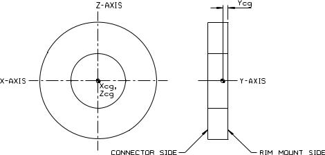
Transducer Center-of-Gravity |
|
|
|||
Transducer Center-of-Gravity and Inertia Specifications |
|||||||
|
|
Material |
|
|
|
|
|
|
|
|
|
|
|
|
|
|
|
Aluminum |
|
|
Titanium |
|
|
|
|
|
|
|
|
|
|
|
Xcg |
0.0 mm |
0.000 in |
|
0.0 mm |
0.000 in |
|
|
Ycg |
19.2 mm |
0.755 in |
|
19.2 mm |
0.755 in |
|
|
Zcg |
0.0 mm |
0.000 in |
|
0.0 mm |
0.000 in |
|
|
Ixx |
180 kg·cm2 |
62 lbm·in2 |
|
290 kg·cm2 |
99 lbm·in2 |
|
|
Iyy |
353 kg·cm2 |
121 lbm·in2 |
|
569 kg·cm2 |
195 lbm·in2 |
|
|
Izz |
180 kg·cm2 |
62 lbm·in2 |
|
290 kg·cm2 |
99 lbm·in2 |
|
|
Low-Profile Transducer Interface (part 1 of 2) |
||||||
Parameter |
|
|
Specification |
|
|
||
|
|
|
|
|
|
|
|
Physical |
|
|
|
|
|
|
|
Height |
|
|
31.75 mm (1.25 in) |
||||
Width |
|
|
431.8 mm (17 in) |
||||
Depth |
|
|
215.9 mm (8.5 in.)* |
||||
Weight |
|
|
1.68 kg (3 lb 11.1 oz) |
||||
Rack Mounting Kit |
|
|
Optional |
|
|
||
|
|
|
|
|
|
|
|
Environmental |
|
|
|
|
|
|
|
Ambient temperature |
|
|
0° C (32° F) to 50° C (122° F) |
||||
Relative humidity |
|
|
0 to 85%, non-condensing |
||||
|
|
|
|
|
|
|
|
26 Hardware Overview |
SWIFT 20 Sensors |

|
Specifications |
|
Low-Profile Transducer Interface (part 2 of 2) |
|
|
Parameter |
Specification |
|
|
|
|
Power Requirements |
|
|
Input voltage |
10–17 V DC |
|
Supply current |
2 A typical, 3 A maximum at 12 V DC |
|
Fuse |
3 A fast-blow |
|
|
|
|
Angular velocity |
|
|
Encoder limit |
2,200 rpm maximum |
|
Processing limit |
10,000 rpm maximum |
|
Encoder resolution |
2048 counts per revolution |
|
|
(512 pulses with quadrature) |
|
|
|
|
Time delay (encoder tick to main output stable) |
12 µs (typical) |
|
|
|
|
Transducer cable length |
100 ft maximum |
|
|
|
|
Shunt cable length |
100 ft maximum |
|
|
|
|
Analog outputs |
|
|
Voltage |
±10 V range† (force and moment outputs) |
|
Capacitive load |
0–5 V sawtooth (angle output) |
|
0.01 µF maximum |
||
Current |
6 mA maximum |
|
Noise at output, with typical gains |
7 mVpp, DC - 500 Hz (typical) |
|
|
15 mVpp, DC - 500 Hz (maximum) |
|
Bandwidth (bridge input to main output)
–3 dB at 30.1 kHz (typical) 90 degree at 16.6 kHz (typical)
*Add 25.4 mm (1.0 in) for ground lugs.
†Standard from MTS. Other full scale voltages can be evaluated and may be provided at special request.
Low-Profile Transducer Interface Communications (part 1 of 2) |
|
Parameter |
Specification |
|
|
Communications Channel # 1 |
|
(Remote Host Connections) |
|
Baud rates |
19,200 Kbits/s |
Parity |
None |
Stop bits |
1 |
Data bits |
8 |
Isolated RS-232/RS-485 interface power |
+5 V DC @ 200 mA maximum |
supply |
|
Electrical interface |
Isolated RS-232 or RS-485 remote host connection |
|
Isolated RS-485 TI to TI connection |
Maximum number of devices that can be part |
32 with RS-232 remote host* |
of a RS-485 multidrop chain |
31 with RS-485 remote host |
Maximum cable length
SWIFT 20 Sensors |
Hardware Overview 27 |

Specifications
Low-Profile Transducer Interface Communications (part 2 of 2)
Parameter |
Specification |
For RS-232 host: |
50 ft from host to the first (nearest) TI, |
|
and |
|
300 ft from the first TI to the last SWIFT TI in the RS- |
|
485 multidrop chain |
For RS-485 host: |
300 ft from host to the last (furthest) TI in the RS-485 |
|
multidrop chain |
*Includes all compatible devices, such as an MTS 407 controller. A maximum of only nine transducer interfaces can be connected, because the addresses are limited to 1–9.
28 Hardware Overview |
SWIFT 20 Sensors |

Calibration
Calibration
Important The following sections include information related to the LowProfile Transducer Interface (TI). For SWIFT transducers designed to operate with the newer Mini TI, there is a separate manual that documents the Mini TI software utilities (MTS part number 100214316).
Each transducer is calibrated by MTS before shipment. The transducer and Low-
Profile TI may be returned to MTS for repair and recalibration as required.
Calibration is performed at MTS on a special fixture that is capable of applying multiple loads to the transducer. During calibration, raw signals are measured. The calibration gains and cross talk compensation values are computed from this raw data. These gains are recorded in a calibration file.
A unique calibration file is supplied for each transducer. The serial number of the Low-Profile TI associated with the transducer is listed at the top of the calibration file. A label with the serial number of the Low-Profile TI box (and the SWIFT sensor with which it was originally calibrated) is located at the back of each Low-Profile TI box.
The calibration file is loaded into the Low-Profile TI non-volatile RAM by MTS before the transducer is shipped. A copy of the file is also provided on a diskette.
MTS verifies the calibration by applying loads to the transducer, measuring the main outputs and checking for accuracy. Final calibration reports are provided with each transducer.
Shunt calibration At the end of the calibration process, a shunt calibration is performed. During a shunt calibration, a resistance is introduced into the bridge circuit. The difference between the shunted and unshunted voltage is the delta shunt reference value for each bridge. That value is saved in the calibration file, which is downloaded from a PC or laptop computer and stored in non-volatile memory in the Low-Profile TI.
At any time afterward, pressing the Shunt button on the front of the Low-Profile TI causes each of the strain gage bridges to be shunted in sequence, and the measured shunt voltage (delta shunt measured value) is compared to the reference value.
An acceptable tolerance range is also loaded into the Low-Profile TI memory during system calibration. One tolerance value is used for all bridges. This value is loaded as a percentage of allowable deviation from the delta shunt values. For example, if the FX1 bridge has a shunt delta reference value of –3.93, and the tolerance is set at 2 (percent), the acceptable range for the measured value would be –3.85 to –4.01.
SWIFT 20 Sensors |
Hardware Overview 29 |

Calibration
When you press the Shunt button, the associated Shunt LED lights. As the LowProfile TI automatically switches through the series of bridges, it verifies that the outputs are within the accepted tolerance range. If all bridge shunt values fall within the tolerance range, the Shunt LED on the front panel will go off (after several seconds). If any bridge fails to fall within the shunt tolerance range, the LED will blink, indicating that the shunt calibration has failed. See the chapter, “Troubleshooting,” on page 127, for more information on dealing with shunt calibration failures.
ShuntTolerance=2
FX1ShuntDeltaRef=-3.91836
FX2ShuntDeltaRef=-3.91896
FY1ShuntDeltaRef=-3.92366
FY2ShuntDeltaRef=-3.91639
FY3ShuntDeltaRef=-3.91824
FY4ShuntDeltaRef=-3.92494
FZ1ShuntDeltaRef=-3.92282
FZ2ShuntDeltaRef=-3.92673
FX1ShuntDeltaMeas=-3.91854
FX2ShuntDeltaMeas=-3.9192
FY1ShuntDeltaMeas=-3.92412
FY2ShuntDeltaMeas=-3.91572
FY3ShuntDeltaMeas=-3.91815
FY4ShuntDeltaMeas=-3.92464
FZ1ShuntDeltaMeas=-3.9227
FZ2ShuntDeltaMeas=-3.92646
Example of Calibration File Shunt Data
The above example shows shunt data from the calibration file. This data may be transferred, using the TIXFER program, from the transducer interface RAM to a computer or from a computer to the transducer interface RAM. Note that items marked ShuntDeltaMeas are uploaded from RAM, but not downloaded from the computer. (For more information on TIXFER, see the chapter, “Software Utilities.”
Shunt verification You can check the electrical integrity of a transducer at any time by pressing the Shunt switch. Subsequent shunt commands compare the current feedback values against those stored in the Low-Profile TI. You may set the tolerance values for each Low-Profile TI by editing the calibration file (see the chapter, “Setting up the Transducer Interface”, for instructions).
If the current feedback values from a shunt calibration are outside the tolerance, the Shunt LED blinks to indicate a failure.
30 Hardware Overview |
SWIFT 20 Sensors |
Loading...