


 Loading...
MTS Material Test System Operation
100-196-370 D |
be certain. |
© 2013 MTS Systems Corporation. All rights reserved.
MTS, TestStar, and TestWare registered trademarks of MTS Systems Corporation within the United States. These trademarks may be protected in other countries.
All other trademarks or service marks are property of their respective owners.
Contents
1.0 Preface |
5 |
1.1.0 Before You Begin............................................................................................................................ |
6 |
1.2.0 Documentation Conventions........................................................................................................... |
6 |
2.0 Technical Support |
9 |
2.1.0 How to Get Technical Support...................................................................................................... |
10 |
2.2.0 Before You Contact MTS.............................................................................................................. |
10 |
2.3.0 If You Contact MTS by Phone...................................................................................................... |
12 |
2.4.0 Problem Submittal Form in MTS Manuals................................................................................... |
13 |
3.0 Introduction |
15 |
3.1.0 Manual Overview.......................................................................................................................... |
16 |
3.2.0 Typical Test System Configuration............................................................................................... |
16 |
3.2.1.0 Load Frame Test Controller........................................................................................... |
20 |
3.2.2.0 Servohydraulic and Mechanical Components................................................................ |
21 |
3.3.0 System Control Theory................................................................................................................. |
22 |
3.4.0 Interlocks....................................................................................................................................... |
24 |
4.0 Safety |
25 |
4.1.0 Overview....................................................................................................................................... |
26 |
4.1.1.0 Safety Information Overview......................................................................................... |
26 |
4.1.2.0 Hazard Placard Placement.............................................................................................. |
26 |
4.2.0 Safety Practices............................................................................................................................. |
27 |
4.2.1.0 General Safety Practices................................................................................................. |
27 |
4.2.2.0 Safety Practices Before Operating the System............................................................... |
27 |
4.2.3.0 Safety Practices While Operating the System ............................................................... |
31 |
5.0 Installation Guidelines |
35 |
5.1.0 Installation Guidelines................................................................................................................... |
36 |
5.2.0 Facility Preparation....................................................................................................................... |
36 |
5.3.0 Electrical Power Distribution........................................................................................................ |
38 |
5.4.0 Grounding Requirements.............................................................................................................. |
39 |
5.5.0 Test Controller and Console Requirements................................................................................... |
39 |
5.6.0 Cooling Water Requirements........................................................................................................ |
40 |
MTS Material Test System Operation 3
5.7.0 Connecting the System Components............................................................................................. |
40 |
5.8.0 System Startup............................................................................................................................... |
41 |
6.0 Getting Started |
43 |
6.1.0 Overview....................................................................................................................................... |
44 |
6.2.0 Define the Test Configuration....................................................................................................... |
44 |
6.2.1.0 Load Unit Setup............................................................................................................. |
44 |
6.2.2.0 Select and Set Up the Data Acquisition Equipment....................................................... |
45 |
6.2.3.0 Set Up the Counter......................................................................................................... |
45 |
6.2.4.0 Set Up the Underpeak Detector...................................................................................... |
45 |
6.3.0 Define the Test Parameters............................................................................................................ |
46 |
6.3.1.0 Select Appropriate Range............................................................................................... |
46 |
6.3.2.0 Define Test Program....................................................................................................... |
46 |
6.3.3.0 Calculate Error Detection Level..................................................................................... |
47 |
6.3.4.0 Calculate Upper and Lower Limit Detector Levels....................................................... |
48 |
6.3.5.0 Calculate Underpeak Detector Levels............................................................................ |
50 |
6.4.0 Select Test Setup Methods............................................................................................................ |
52 |
6.4.1.0 Servo Loop Adjustments................................................................................................ |
52 |
6.5.0 Determine the Crosshead Position................................................................................................ |
55 |
7.0 Operation |
57 |
7.1.0 Operation Overview...................................................................................................................... |
58 |
7.2.0 Initial Setup................................................................................................................................... |
58 |
7.3.0 Set Detector Levels....................................................................................................................... |
59 |
7.4.0 Adjust Displacement Servo Loop (optional)................................................................................. |
60 |
7.5.0 Install the Specimen...................................................................................................................... |
61 |
7.5.1.0 Specimen Installation with Model 370 Load Frame...................................................... |
61 |
7.5.2.0 Specimen Installation with 318, 331, and 359 Load Frames......................................... |
63 |
7.6.0 Adjust Load Servo Loop............................................................................................................... |
65 |
7.7.0 Set Up the Program, Detectors, Counter, and Data Acquisition................................................... |
67 |
7.8.0 Run the Test................................................................................................................................... |
68 |
8.0 Routine Maintenance |
69 |
8.1.0 Maintenance Overview.................................................................................................................. |
70 |
9.0 Decommission |
75 |
9.1.0 Decommission Test System........................................................................................................... |
76 |
4 MTS Material Test System Operation

1.0 Preface
Topics: |
|
|
• |
Before You Begin..................................................................................................................................... |
6 |
• |
Documentation Conventions.................................................................................................................... |
6 |
MTS Material Test System Operation 5

1.0 Preface
1.1.0 Before You Begin
Safety first!
Before you use your MTS product or system, read and understand the safety information provided with your system. Improper installation, operation, or maintenance can result in hazardous conditions that can cause severe personal injury or death, or damage to your equipment and specimen. Again, read and understand the safety information provided with your system before you continue. It is very important that you remain aware of hazards that apply to your system.
Other MTS manuals
In addition to this manual, you may receive additional manuals in paper or electronic form.
You may also receive an MTS System Documentation CD. It contains an electronic copy of the manuals that pertain to your test system.
Controller and application software manuals are typically included on the software CD distribution disc(s).
1.2.0 Documentation Conventions
The following paragraphs describe some of the conventions that are used in your MTS manuals.
Hazard conventions
Hazard notices may be embedded in this manual. These notices contain safety information that is specific to the activity to be performed. Hazard notices immediately precede the step or procedure that may lead to an associated hazard. Read all hazard notices carefully and follow all directions and recommendations.Three different levels of hazard notices may appear in your manuals. Following are examples of all three levels.
(for general safety information, see the safety information provided with your system.)
DANGER:
Danger notices indicate the presence of a hazard with a high level of risk which, if ignored, will result in death, severe personal injury, or substantial property damage.
WARNING:
Warning notices indicate the presence of a hazard with a medium level of risk which, if ignored, can result in death, severe personal injury, or substantial property damage.
CAUTION:
Caution notices indicate the presence of a hazard with a low level of risk which, if ignored, could cause moderate or minor personal injury or equipment damage, or could endanger test integrity.
6 MTS Material Test System Operation

1.0 Preface
Other special text conventions
Important:
Important notices provide information about your system that is essential to its proper function. While not safety-related, if the important information is ignored, test results may not be reliable, or your system may not operate properly.
Note:
Notes provide additional information about operating your system or highlight easily overlooked information.
Recommended:
Recommended notes provide a suggested way to accomplish a task based on what MTS has found to be most effective.
Tip:
Tips provide helpful information or a hint about how to most efficiently accomplish a task.
Access:
Access provides the route you should follow to a referenced item in the software.
Example:
Examples show specific scenarios relating to your product and appear with a shaded background.
Special terms
The first occurrence of special terms is shown in italics.
Illustrations
Illustrations appear in this manual to clarify text. They are examples only and do not necessarily represent your actual system configuration, test application, or software.
Electronic manual conventions
This manual is available as an electronic document in the Portable Document File (PDF) format. It can be viewed on any computer that has Adobe Acrobat Reader installed.
Hypertext links
The electronic document has many hypertext links displayed in a blue font. All blue words in the body text, along with all contents entries and index page numbers, are hypertext links. When you click a hypertext link, the application jumps to the corresponding topic.
MTS Material Test System Operation 7

2.0 Technical Support
Topics: |
|
|
• How to Get Technical Support............................................................................................................... |
10 |
|
• Before You Contact MTS....................................................................................................................... |
10 |
|
• |
If You Contact MTS by Phone............................................................................................................... |
12 |
• |
Problem Submittal Form in MTS Manuals............................................................................................. |
13 |
MTS Material Test System Operation 9

2.0 Technical Support
2.1.0 How to Get Technical Support
Start with your manuals
The manuals supplied by MTS provide most of the information you need to use and maintain your equipment. If your equipment includes software, look for online help and README files that contain additional product information.
Technical support methods
MTS provides a full range of support services after your system is installed. If you have any questions about a system or product, contact Technical Support in one of the following ways.
Web site |
www.mts.com > Contact Us (upper-right corner) > In the Subject field, choose |
|
To escalate a problem; Problem Submittal Form |
Worldwide: tech.support@mts.com |
|
|
Europe: techsupport.europe@mts.com |
Telephone |
Worldwide: 1 800 328 2255 - toll free in U.S.; +1 952 937 4000 - outside U.S. |
|
Europe: +800 81002 222, International toll free in Europe |
Outside the U.S.
For technical support outside the United States, contact your local sales and service office. For a list of worldwide sales and service locations and contact information, use the Global MTS link at the MTS web site:
www.mts.com > Global Presence > Choose a Region
2.2.0 Before You Contact MTS
MTS can help you more efficiently if you have the following information available when you contact us for support.
Know your site number and system number
The site number contains your company number and identifies your equipment type (such as material testing or simulation). The number is typically written on a label on your equipment before the system leaves MTS. If you do not know your MTS site number, contact your sales engineer.
Example site number: 571167
When you have more than one MTS system, the system job number identifies your system. You can find your job number in your order paperwork.
Example system number: US1.42460
10 MTS Material Test System Operation
2.0 Technical Support
Know information from prior technical assistance
If you have contacted MTS about this problem before, we can recall your file based on the:
•MTS notification number
•Name of the person who helped you
Identify the problem
Describe the problem and know the answers to the following questions:
•How long and how often has the problem occurred?
•Can you reproduce the problem?
•Were any hardware or software changes made to the system before the problem started?
•What are the equipment model numbers?
•What is the controller model (if applicable)?
•What is the system configuration?
Know relevant computer information
For a computer problem, have the following information available:
•Manufacturer’s name and model number
•Operating software type and service patch information
•Amount of system memory
•Amount of free space on the hard drive where the application resides
•Current status of hard-drive fragmentation
•Connection status to a corporate network
Know relevant software information
For software application problems, have the following information available:
•The software application’s name, version number, build number, and (if available) software patch number. This information can typically be found in the About selection in the Help menu.
•The names of other applications on your computer, such as:
•Anti-virus software
•Screen savers
•Keyboard enhancers
•Print spoolers
•Messaging applications
MTS Material Test System Operation 11

2.0 Technical Support
2.3.0 If You Contact MTS by Phone
A Call Center agent registers your call before connecting you with a technical support specialist. The agent asks you for your:
•Site number
•Name
•Company name
•Company address
•Phone number where you can be reached
If your issue has a notification number, please provide that number. A new issue will be assigned a unique notification number.
Identify system type
To enable the Call Center agent to connect you with the most qualified technical support specialist available, identify your system as one of the following types:
•Electrodynamic material test system
•Electromechanical material test system
•Hydromechanical material test system
•Vehicle test system
•Vehicle component test system
•Aero test system
Be prepared to troubleshoot
Prepare to perform troubleshooting while on the phone:
•Call from a telephone close to the system so that you can implement suggestions made over the phone.
•Have the original operating and application software media available.
•If you are not familiar with all aspects of the equipment operation, have an experienced user nearby to assist you.
Write down relevant information
In case Technical Support must call you:
•Verify the notification number.
•Record the name of the person who helped you.
•Write down any specific instructions.
12 MTS Material Test System Operation

2.0 Technical Support
After you call
MTS logs and tracks all calls to ensure that you receive assistance for your problem or request. If you have questions about the status of your problem or have additional information to report, please contact Technical Support again and provide your original notification number.
2.4.0 Problem Submittal Form in MTS Manuals
Use the Problem Submittal Form to communicate problems with your software, hardware, manuals, or service that are not resolved to your satisfaction through the technical support process. The form includes check boxes that allow you to indicate the urgency of your problem and your expectation of an acceptable response time. We guarantee a timely response—your feedback is important to us.
You can access the Problem Submittal Form at www.mts.com > Contact Us (upper-right corner) > In the
Subject field, choose To escalate a problem; Problem Submittal Form
MTS Material Test System Operation 13

3.0 Introduction
Topics: |
|
|
• |
Manual Overview................................................................................................................................... |
16 |
• Typical Test System Configuration......................................................................................................... |
16 |
|
• |
System Control Theory.......................................................................................................................... |
22 |
• |
Interlocks................................................................................................................................................ |
24 |
MTS Material Test System Operation 15
3.0 Introduction
3.1.0 Manual Overview
This manual provides operating guidelines, installation guidelines, and safety practices for operation of an MTS Test System. This manuals deals primarily with the hardware components used to configure a typical MTS load frame based materials testing system: the load frame, the grips and fixtures used to secure the specimen during testing, and the MTS Hydraulic Power Unit. It also contains information on the MTS controller and a general description of the test system control theory.
This manual does not contain information on the software used to create and run specific testing applications such as low cycle fatigue or monotonic tension. For this information, refer to your software manuals; for example TestSuite or TestWorks.
An MTS test system can be designed for a wide variety of testing applications. To provide maximum flexibility for operation, the information in this manual is written for a typical system.
In addition to studying this manual, MTS recommends you become acquainted with the system by reading the introductory sections of the product manuals.
3.2.0 Typical Test System Configuration
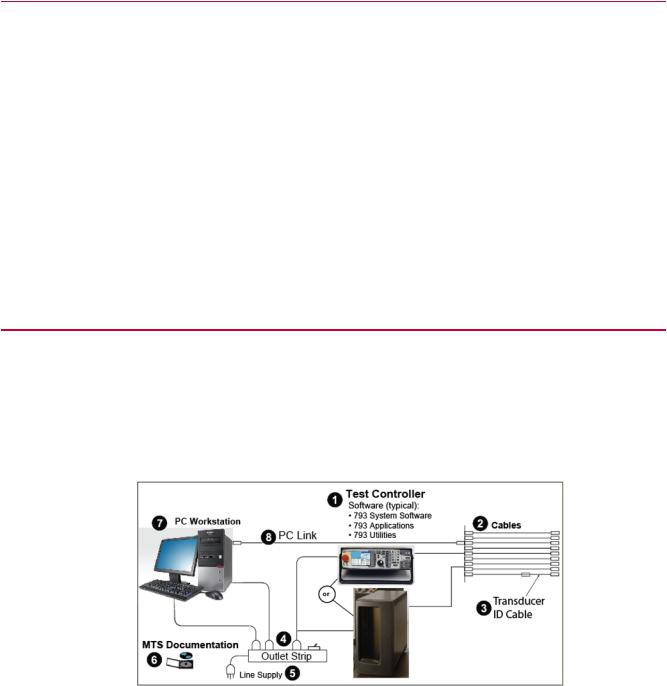
An MTS Test System can be designed for a wide variety of testing applications.To provide maximum flexibility for operation, the information in this manual is written for the typical system that includes as a minimum configuration a test controller, load frame, and hydraulic power unit.
The following illustrations show the common system components and uses the MTS Landmark load frame for illustration purposes. All MTS load frames have similar components. Some load frames will have a t-slot tables as a baseplate to accommodate various fixtures and actuator and column positioning.
Figure 1: Test Controller and Components
16 MTS Material Test System Operation
3.0 Introduction
Item |
Description |
||
1 |
Test Controller Software (Typical) |
||
|
• |
793 |
System Software |
|
• |
793 |
Applications |
|
• |
793 |
Utilities |
2 |
Cables |
|
|
3 |
Transducer ID Cable |
||
4 |
Outlet Strip |
||
5 |
Line Supply |
||
6 |
MTS Documentation |
||
7 |
PC Workstation |
||
8 |
PC Link |
||
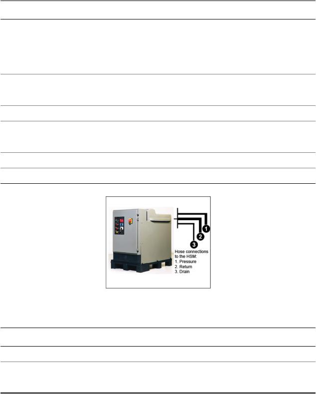
Figure 2: Hydraulic Power Unit
Table 1: Hose connections to the HSM
Item |
Description |
1 |
Pressure |
2 |
Return |
3 |
Drain |
MTS Material Test System Operation 17

3.0 Introduction
Figure 3: Hydraulic Service Manifold
Table 2: Hose connections from the HPU and to the actuators
Item |
Description |
1 |
Pressure |
2 |
Return |
3 |
Drain |
|
Figure 4: Load Frame |
Item |
Description |
1 |
Servovalve |
18 MTS Material Test System Operation
3.0 Introduction
Item |
Description |
|
2 |
Hydraulic service manifold |
|
3 |
Hose connections: |
|
|
• |
Pressure |
|
• |
Return |
|
• |
Drain |
4 |
Hand set (some models) |
|
5 |
Actuator speed switch (some models) |
|
6 |
E-Stop button |
|
7 |
Hydraulic lift lock controls |
|
8 |
Grip controls |
|
9 |
Linear actuator |
|
10 |
Load cell |
|
Additional testing accessories are also available. For information on optional accessories, refer to the individual product manuals.
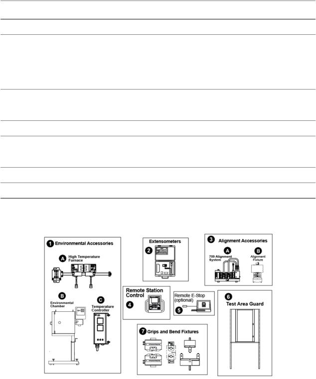
Figure 5: Testing Accessories
MTS Material Test System Operation 19

3.0 Introduction |
|
Item |
Description |
1 |
Environmental Accessories |
|
1A. High temperature furnace |
|
1B. Environmental chamber |
|
1C. Temperature controller |
2 |
Extensometers |
3 |
Alignment accessories |
|
3A. High temperature furnace |
|
3B. Environmental chamber |
4 |
Remote station control |
5 |
Remote E-Stop (optional) |
6 |
Test area guard |
7 |
Grips and bend fixtures |
3.2.1.0 Load Frame Test Controller
The test controller can be either a FlexTest SE Basic, FlexTest SE Plus, FlexTest GT, or FlexTest 40/60/100/200.
Note:
Because the FlexTest 40 is the most common test controller used on the MTS Landmark System, this manual will primarily focus on that controller.
The FlexTest 40, FlexTest SE Plus, and FlexTest SE 2-Channel are single station PC-based digital controllers. The FlexTest 60/100/200 controllers are PC-based multi-station digital controllers. In more complex testing situations, the multi-station controller controls many channels on a number of independent stations; with one or more of the stations being a load frame based test system. These test controllers consist of:
•A PC running Series 793 Software (except the FlexTest SE Basic).
•A chassis equipped with Series 493 or Series 494 electronics.
•A handset for load frame control during specimen loading and unloading. The handset is also used for setup and can initiate tests at the load frame.
•The Station Manager application running on the PC as the primary test interface.
•A software application (such as MultiPurpose TestWare) to provide the command and data acquisition functions of running a test.
The FlexTest SE Basic is nonautomated and operates from the front panel controls.
20 MTS Material Test System Operation
3.0 Introduction
3.2.2.0 Servohydraulic and Mechanical Components
The following paragraphs briefly describe the servohydraulic and mechanical components that are typical supplied with the MTS Landmark System.
Load frame
There are a variety of load frames that can be supplied with the system. The load frame is the mechanical foundation of the test system in which the load cell transducer, specimen fixturing or grips, and hydraulic actuator are mounted.
The load frame can be configured with hydraulic-controlled crosshead locks and lifts that allow convenient crosshead positioning during specimen installation. (Manual crosshead locks and lifts and manual crosshead locks and hydraulic lifts are also available on some models.)
Load frames come in a variety of configurations, but all have the same basic components described below. Some examples are:
•Basic two-column floor-standing frames for general material testing such as the MTS Landmark Load Frame
•Table-top frames for biomechanical and biomaterials testing such as the MTS Bionix Load Frame
•T-slot baseplate frames for general component testing such as the MTS Model 322 Load Frame
•Frames specifically designed for high cycle elastomer testing such as the MTS Model 331.02 and 331.05 Load Frames.
•Frames with high mass base designs for shock absorber testing such as the MTS Model 84X and 85x Load Frames
Hydraulic actuator
The hydraulic actuator is typically mounted in the base of the load frame; some load frames can have crosshead mounted actuators. It is the force-generating and/or positioning device in the system. Hydraulic fluid is applied to either side of the actuator's piston to cause its piston rod to extend or retract.
Servovalve(s)
The servovalve converts a control signal (from the test controller) to control the direction and amount of fluid flow to the actuator. This regulated hydraulic fluid flow controls the displacement or force being applied to the test specimen.
Hydraulic service manifold
The hydraulic service manifold contains the required hydraulic porting to accommodate the servovalve(s), an actuator, and the crosshead lifts.The actuator and servovalve(s) are mounted to the manifold.The manifold includes a low hydraulic flow feature that lets you limit the velocity of the actuator for specimen installation.
Accumulators
The accumulators suppress line-pressure fluctuations. The pressure-line accumulators provide fluid storage so a constant line pressure can be maintained at the servovalve(s) for maximum performance.The return-line accumulator minimizes return-line pressure fluctuations.
MTS Material Test System Operation 21

3.0 Introduction
Hydraulic power supply
The hydraulic power unit (HPU) provides pressurized hydraulic fluid to the servovalve. An HPU typically includes a reservoir for the hydraulic fluid, a pump to pressurize the hydraulic fluid, a motor to run the pump, a heat exchanger to cool the hydraulic fluid, and sensors to monitor the level, pressure, and temperature of the hydraulic fluid.
Transducer(s)
The load cell transducer, mounted underneath the load frame crosshead, is used to measure the polarity and magnitude of the force that is applied to the specimen.
The extensometer is a sensor attached to a specimen that measures a dimensional change (gage length or strain) that occurs in the specimen while being tested. Extensometers use a Wheatstone bridge circuit to detect the dimensional changes.
The LVDT (linear variable differential transformer) transducer is mounted inside the hydraulic actuator. The LVDT is used to measure the axial position (or displacement) of the actuator piston rod. Encoders are used in axial/torsional systems to measure rotation.
Specimen fixtures or grips
Either fixtures or grips are used to hold the specimen in alignment with the force train during the test. The force train is comprised of the servohydraulic and mechanical components which receive the forces applied by the hydraulic actuator.
Environmental products
Optional environmental products can be incorporated into the test system configuration. These include temperature chambers, furnaces, and associated temperature controllers. When using products to control specimen temperature, be sure to use other products (for example grips and extensometers) that can withstand the test temperatures.
Test area enclosure
MTS recommends the use of test area enclosures. Protective enclosures such as cages or shields should be used when you work with hazardous test specimens (for example, brittle or fragmenting materials or materials that are internally pressurized). If a test area enclosure is not purchased form MTS< it is the customer’s responsibility to ensure a safe working environment,
3.3.0 System Control Theory
The test system uses a control technique referred to as “closed-loop control.” The theory of this control technique and the various control modes and interlock detection methods that can be used are described in the following subsections.
Closed loop control
In a test system, the test controller (for example the MTS FlexTest 40) provides closed-loop control of the system’s mechanical and hydraulic components.
22 MTS Material Test System Operation
3.0 Introduction
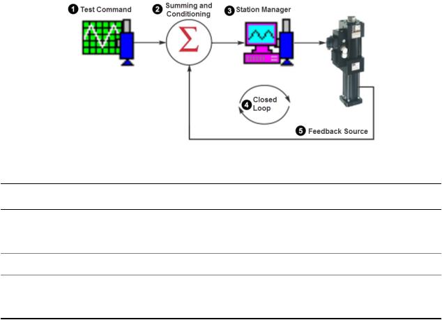
Table 3: Simple Control diagram
Item |
Description |
1 |
Test command |
2 |
Summing and conditioning |
3 |
Station manager |
4 |
Closed loop |
5 |
Feedback source |
When reduced to its basic form, a Series 793 test system typically includes these elements. (The command can also be provided by a function generator or MultiPurpose TestWare).
The configuration of the devices provides a means of comparing a command (programmer output) signal with a feedback (transducer output) signal to generate a signal that controls the servovalve. The servovalve controls hydraulic flow to the actuator which moves the actuator piston rod. The actuator piston rod applies the force required to load or displace the specimen being tested.
The control method is referred to as “closed-loop control” because the process of command, feedback, comparison, and servovalve control is totally a function of the control circuitry and occurs without operator interaction.
In closed-loop control, the programmer is used to generate the command signal. The controller provides the necessary circuitry for the comparison of the command signal and the feedback signal. The controller also contains the circuits that generate the servovalve control signal and condition the transducer output.
Control modes
Typical control modes that can be used to control the test include load, displacement, and strain.
The control mode uses the controller's summing junction to compare the command signal and the conditioned feedback signal to produce a DC error signal. The polarity and magnitude of the DC error signal causes the valve driver circuit to produce a signal that opens the servovalve spool in a direction and by an amount necessary to allow fluid to flow into the actuator and cause the desired force, displacement, or strain. As the command and feedback change, the summing junction continuously generates a DC error signal that drives the servovalve to create the desired actuator response.
MTS Material Test System Operation 23

3.0 Introduction
3.4.0 Interlocks
The test controller incorporates interlock circuitry that can automatically stop a test when a system problem, specimen failure, or an operator error could result in unwanted or unexpected actuator movement. The test controller interlock circuitry will cause one of two interlocks to occur in response to specific conditions encountered during testing. These interlocks are:
•Hydraulic Interlock – stops the program and removes hydraulic pressure from the system.
•Program Interlock – stops the current test program when certain test parameters are not met or are exceeded.
Because specimen installation procedures and testing situations can be adversely affected by the sudden loss of actuator pressure that accompanies a hydraulic interlock, the operator might choose to enable or disable the interlock detectors during system setup. Disabling the interlock detectors allow the operator to prevent a hydraulic shutdown if an interlock condition occurs. the following table lists the possible types of interlock conditions for the test controller.
Table 4: Interlocks
Condition |
Cause |
Type of Interlock |
|
Emergency Stop |
Emergency Stop or E-Stop button pressed |
Hydraulic |
|
Program Aux |
Open circuit at the Prog Intlk rear panel connector |
Program |
|
Hydraulic event |
Fault in the performance of hydraulic components |
Hydraulic |
|
Mechanical event |
Fault in the performance of mechanical components |
Hydraulic |
|
End-of Count |
Completion of a preset number of cycles in the current |
Hydraulic or Program |
|
|
test program |
|
|
Underpeak |
Selected signal fails to reach a preset minimum or |
Hydraulic with indicator |
|
|
maximum level |
option |
1 |
|
|
|
|
Error |
When the control channel's DC error signal exceeds |
Hydraulic with indicator |
|
|
a preset maximum level |
option |
2 |
|
|
|
|
Upper LimitLower Limit |
Transducer feedback signal exceeds a preset |
Hydraulic with indicator |
|
|
minimum or maximum level |
option |
3 |
|
|
|
|
1These interlocks can be set to indicate only. For further information on configuring these interlocks, refer to the test controller documentation.
2These interlocks can be set to indicate only. For further information on configuring these interlocks, refer to the test controller documentation.
3These interlocks can be set to indicate only. For further information on configuring these interlocks, refer to the test controller documentation.
24 MTS Material Test System Operation
Loading...