


 Loading...
m
be certain.
Series 646 Hydraulic Collet Grips
Product Information
Model 646.10
Model 646.25
011-558-204 H
Copyright information Trademark information
© 1991, 2001, 2004, 2008, 2009 MTS Systems Corporation. All rights reserved.
MTS is a registered trademark of MTS Systems Corporation within the United States. This trademark may be protected in other countries.
Molykote is a registered trademark of Dow Chemical Corporation. All other trademarks or service marks are property of their respective owners.
Publication information |
MANUAL PART NUMBER |
PUBLICATION DATE |
|
|
|
|
011-558-204 B |
May 1991 |
|
|
|
|
011-558-204 C |
February 2001 |
|
|
|
|
011-558-204 D |
June 2001 |
|
|
|
|
011-558-204 E |
April 2004 |
|
|
|
|
011-558-204 F |
March 2008 |
|
|
|
|
011-558-204 G |
April 2009 |
|
|
|
|
011-558-204 H |
August 2012 |
|
|
|
2 |
Manual Template 4.3 |

Contents
Technical Support |
5 |
|
|
|
||
|
|
|
||||
How to Get Technical Support |
5 |
|
||||
Before You Contact MTS |
5 |
|
|
|||
If You Contact MTS by Phone |
7 |
|
||||
Problem Submittal Form in MTS Manuals |
8 |
|||||
Preface 9 |
|
|
|
|
|
|
|
|
|
|
|||
Before You Begin 9 |
|
|
|
|||
Conventions |
10 |
|
|
|
|
|
Documentation Conventions |
10 |
|
||||
Introduction |
13 |
|
|
|
|
|
|
||||||
Series 646 Hydraulic Collet Grips Component Identification 14 |
||||||
About Series 646 Hydraulic Collet Grips |
16 |
|||||
About Gripping Specimens |
16 |
|
||||
Collet Sets |
16 |
|
|
|
|
|
Spiral Washers |
16 |
|
|
|
||
Couplings |
17 |
|
|
|
|
|
Specifications |
18 |
|
|
|
|
|
Series 646 Hydraulic Collet Grips Dimensions 18
Model 646 Grip with Furnace Extensions Dimensions 19
Series 646 |
Hydraulic Collet Grips Force and Torque Capacities 20 |
Series 646 |
Hydraulic Collet Grips Specifications—Round Specimens 22 |
Series 646 |
Hydraulic Collet Grips Specifications—Flat Specimens 23 |
Series 646 |
Hydraulic Collet Grips Specifications—Threaded Specimens 24 |
Safety Information 25
General Safety Practices: Grips and Fixtures 25
General Precautions for Environmental Components 30
Hazard Placard Placement 30
Series 646 Hydraulic Collet Grips |
Contents |
3 |

Installation |
33 |
|
|
|
|
|
|
|
|
|
|
|
|
||||
646 Hydraulic Grip Lift Points |
33 |
|
|
|
||||
About Axial Grip Installation |
34 |
|
|
|
|
|||
Axial Grip Installation Procedure |
36 |
|
|
|
||||
About Axial-Torsional Grip Installation |
40 |
|
||||||
Axial Torsional Grip Installation Procedure |
41 |
|||||||
Grip Alignment |
45 |
|
|
|
|
|
|
|
How to Preload the Spiral Washers |
45 |
|
|
|||||
Grip Water Cooling Assembly Configurations for Servohydraulic Frames 48 |
||||||||
Operation 51 |
|
|
|
|
|
|
|
|
|
|
|
|
|
||||
Determine the Gripping Pressure |
52 |
|
|
|
||||
Grip Alignment Markings |
54 |
|
|
|
|
|
||
Installing a Collet for a Round Specimen |
55 |
|||||||
Installing a Collet for a Flat Specimen |
56 |
|
||||||
Installing a Collet for a Threaded Specimen |
57 |
|||||||
Installing a Round or Flat Specimen |
59 |
|
|
|||||
Installing a Threaded Specimen |
60 |
|
|
|
||||
Adjust Water Cooling Flow |
62 |
|
|
|
|
|||
Removing Specimen 63 |
|
|
|
|
|
|
||
Maintenance |
65 |
|
|
|
|
|
|
|
|
|
|
|
|
|
|||
Hydraulic Hoses and Fittings |
65 |
|
|
|
|
|||
Collets |
65 |
|
|
|
|
|
|
|
Water Cooling Components |
65 |
|
|
|
|
|||
Daily Inspections |
65 |
|
|
|
|
|
|
|
4 |
Contents |
Series 646 Hydraulic Collet Grips |

Technical Support
How to Get Technical Support
Start with your manuals
Technical support methods
www.mts.com
Telephone
The manuals supplied by MTS provide most of the information you need to use and maintain your equipment. If your equipment includes software, look for online help and README files that contain additional product information.
If you cannot find answers to your technical questions from these sources, you can use the Internet, e-mail, telephone, or fax to contact MTS for assistance.
MTS provides a full range of support services after your system is installed. If you have any questions about a system or product, contact Technical Support in one of the following ways.
The web site provides access to our technical support staff by means of an onlineform:
www.mts.com > Contact MTS > Service & Technical Support button
tech.support@mts.com
MTS Call Center 800-328-2255
Weekdays 7:00 A.M. to 5:00 P.M., Central Time
Fax 952-937-4515
Please include “Technical Support” in the subject line.
Outside the U.S. For technical support outside the United States, contact your local sales and service office. For a list of worldwide sales and service locations and contact information, use the Global MTS link at the MTS web site:
www.mts.com > Global MTS > (choose your region in the right-hand column) > (choose the location closest to you)
Before You Contact MTS
Know your site number and system number
MTS can help you more efficiently if you have the following information available when you contact us for support.
The site number contains your company number and identifies your equipment type (such as material testing or simulation). The number is typically written on a label on your equipment before the system leaves MTS. If you do not know your MTS site number, contact your sales engineer.
Example site number: 571167
When you have more than one MTS system, the system job number identifies your system. You can find your job number in your order paperwork.
Example system number: US1.42460
Series 646 Hydraulic Collet Grips |
Technical Support |
5 |
Know information from prior technical assistance
Identify the problem
Know relevant computer information
Know relevant software information
If you have contacted MTS about this problem before, we can recall your file based on the:
•MTS notification number
•Name of the person who helped you
Describe the problem and know the answers to the following questions:
•How long and how often has the problem occurred?
•Can you reproduce the problem?
•Were any hardware or software changes made to the system before the problem started?
•What are the equipment model numbers?
•What is the controller model (if applicable)?
•What is the system configuration?
For a computer problem, have the following information available:
•Manufacturer’s name and model number
•Operating software type and service patch information
•Amount of system memory
•Amount of free space on the hard drive where the application resides
•Current status of hard-drive fragmentation
•Connection status to a corporate network
For software application problems, have the following information available:
•The software application’s name, version number, build number, and (if available) software patch number. This information can typically be found in the About selection in the Help menu.
•The names of other applications on your computer, such as:
–Anti-virus software
–Screen savers
–Keyboard enhancers
–Print spoolers
–Messaging applications
6 |
Technical Support |
Series 646 Hydraulic Collet Grips |
If You Contact MTS by Phone
A Call Center agent registers your call before connecting you with a technical support specialist. The agent asks you for your:
•Site number
•Name
•Company name
•Company address
•Phone number where you can be reached
Identify system type
Be prepared to troubleshoot
Write down relevant information
After you call
If your issue has a notification number, please provide that number. A new issue will be assigned a unique notification number.
To enable the Call Center agent to connect you with the most qualified technical support specialist available, identify your system as one of the following types:
•Electromechanical material test system
•Hydromechanical material test system
•Vehicle test system
•Vehicle component test system
•Aero test system
Prepare to perform troubleshooting while on the phone:
•Call from a telephone close to the system so that you can implement suggestions made over the phone.
•Have the original operating and application software media available.
•If you are not familiar with all aspects of the equipment operation, have an experienced user nearby to assist you.
In case Technical Support must call you:
•Verify the notification number.
•Record the name of the person who helped you.
•Write down any specific instructions.
MTS logs and tracks all calls to ensure that you receive assistance for your problem or request. If you have questions about the status of your problem or have additional information to report, please contact Technical Support again and provide your original notification number.
Series 646 Hydraulic Collet Grips |
Technical Support |
7 |
Problem Submittal Form in MTS Manuals
Use the Problem Submittal Form to communicate problems with your software, hardware, manuals, or service that are not resolved to your satisfaction through the technical support process. The form includes check boxes that allow you to indicate the urgency of your problem and your expectation of an acceptable response time. We guarantee a timely response—your feedback is important to us.
Access the Problem Submittal Form:
•In the back of many MTS manuals (postage paid form to be mailed to MTS)
•www.mts.com > Contact Us > Problem Submittal Form button (electronic form to be e-mailed to MTS)
8 |
Technical Support |
Series 646 Hydraulic Collet Grips |

Preface
Before You Begin
Safety first!
Other MTS manuals
Before you use your MTS product or system, read and understand the Safety manual and any other safety information provided with your system. Improper installation, operation, or maintenance can result in hazardous conditions that can cause severe personal injury or death, or damage to your equipment and specimen. Again, read and understand the safety information provided with your system before you continue. It is very important that you remain aware of hazards that apply to your system.
In addition to this manual, you may receive additional manuals in paper or electronic form.
You may also receive an MTS System Documentation CD. It contains an electronic copy of the manuals that pertain to your test system, such as:
•Hydraulic and mechanical component manuals
•Assembly drawings
•Parts lists
•Operation manual
•Preventive maintenance manual
Controller and application software manuals are typically included on the software CD distribution disc(s).
Series 646 Hydraulic Collet Grips |
Preface |
9 |

Conventions
Conventions
Documentation Conventions
Hazard conventions
Notes
Special terms
Illustrations
Electronic manual conventions
The following paragraphs describe some of the conventions that are used in your MTS manuals.
Hazard notices may be embedded in this manual. These notices contain safety information that is specific to the activity to be performed. Hazard notices immediately precede the step or procedure that may lead to an associated hazard. Read all hazard notices carefully and follow all directions and recommendations. Three different levels of hazard notices may appear in your manuals. Following are examples of all three levels.
Note For general safety information, see the safety information provided with your system.

 DANGER
Danger notices indicate the presence of a hazard with a high level of risk which, if ignored, will result in death, severe personal injury, or substantial property damage.

 WARNING
Warning notices indicate the presence of a hazard with a medium level of risk which, if ignored, can result in death, severe personal injury, or substantial property damage.

 CAUTION
Caution notices indicate the presence of a hazard with a low level of risk which, if ignored, could cause moderate or minor personal injury or equipment damage, or could endanger test integrity.
Notes provide additional information about operating your system or highlight easily overlooked items. For example:
Note Resources that are put back on the hardware lists show up at the end of the list.
The first occurrence of special terms is shown in italics.
Illustrations appear in this manual to clarify text. They are examples only and do not necessarily represent your actual system configuration, test application, or software.
This manual is available as an electronic document in the Portable Document File (PDF) format. It can be viewed on any computer that has Adobe Acrobat Reader installed.
10 |
Preface |
Series 646 Hydraulic Collet Grips |
Conventions
Hypertext links The electronic document has many hypertext links displayed in a blue font. All blue words in the body text, along with all contents entries and index page numbers, are hypertext links. When you click a hypertext link, the application jumps to the corresponding topic.
Series 646 Hydraulic Collet Grips |
Preface |
11 |
Conventions
12 |
Preface |
Series 646 Hydraulic Collet Grips |

Introduction
Contents
What you need to know
Related products
MTS Series 646 Hydraulic Collet Grips grasp and hold a specimen in place during testing, and provide a constant, hydraulically actuated gripping force regardless of the applied test loads. They are designed to perform in a wide variety of testing applications including high and low cycle fatigue, tension, and compression testing.
Series 646 Hydraulic Collet Grips Component Identification 14 About Series 646 Hydraulic Collet Grips 16
Specifications 18
646 Hydraulic Collet Grip
646 Hydraulic Collet Grip
Series 646 Hydraulic Collet Grips
This manual assumes that you know how to use your system controller. See the appropriate manual for information about performing any controller-related step in this manual’s procedures. You are expected to know how to do the following:
•Turn hydraulic pressure on and off.
•Select a control mode.
•Manually adjust the actuator position.
•Monitor a sensor signal.
•Zero a sensor output.
The grips are usually controlled with a dedicated hydraulic supply. See the Series 685 Hydraulic Grip Supply Product Information manual (MTS part number 015- 205-001).
Series 646 Hydraulic Collet Grips |
Introduction |
13 |

Series 646 Hydraulic Collet Grips Component Identification
Shim
Spiral
Washers
Threaded
Mounting 

Stud
 Force Transducer (attached to the load unit crosshead)
Upper Grip
Adapter
Plate
Upper
 Coupling
|
|
|
|
|
|
|
|
|
|
|
|
|
|
|
|
|
|
|
|
|
|
|
|
|
|
|
|
|
|
|
|
|
|
|
|
|
|
|
|
|
|
|
|
|
|
|
|
|
|
|
|
|
|
|
|
|
|
|
|
|
|
|
|
|
|
|
|
|
|
|
|
|
|
|
|
|
|
|
|
|
|
|
|
|
|
|
|
|
|
|
|
|
|
|
|
|
|
|
|
|
|
|
|
|
|
|
|
|
|
|
|
|
|
|
|
|
|
|
|
|
|
|
|
|
|
|
|
|
|
|
|
|
|
|
|
|
|
|
|
|
|
|
|
|
|
|
|
|
|
|
|
|
|
|
|
|
|
|
|
|
|
|
|
|
|
|
|
|
|
|
|
|
|
|
|
|
|
|
|
|
|
|
|
|
|
|
|
|
|
|
|
|
|
|
|
|
|
|
|
|
|
|
|
|
|
|
|
|
|
|
|
|
|
|
|
|
|
|
|
|
|
|
|
|
|
|
|
|
|
|
|
|
|
|
|
|
|
|
|
|
|
|
|
|
|
|
|
|
|
|
|
|
|
|
|
|
|
|
|
|
|
|
|
|
|
|
|
|
|
|
|
|
|
|
|
|
|
|
|
|
|
|
|
|
|
|
|
|
|
|
|
|
|
|
|
|
|
|
|
|
|
|
|
|
|
|
|
|
|
|
|
|
|
|
|
|
|
|
|
|
|
|
|
|
|
|
|
|
|
|
|
|
|
|
|
|
|
|
|
|
|
|
|
|
|
|
|
|
|
|
|
|
|
|
|
|
|
|
|
|
|
|
|
|
|
|
|
|
|
|
|
|
|
|
|
|
|
|
|
|
|
|
|
|
|
|
|
|
|
|
|
|
|
|
|
|
|
|
|
|
|
|
|
|
|
|
|
|
|
|
|
|
|
|
|
|
|
|
|
|
|
|
|
|
|
|
|
|
|
|
|
|
|
|
|
|
|
|
|
|
|
|
|
|
|
|
|
|
|
|
|
|
|
|
|
|
|
|
|
|
|
|
|
|
|
|
|
|
|
|
|
|
|
|
|
|
|
|
|
|
|
|
|
|
|
|
|
|
|
|
|
|
|
|
|
|
|
|
|
|
|
|
|
|
|
|
Collets |
|
Hydraulic Pressure |
|
|
||||||||||||||||||||||||||||||||||
|
and Return Ports |
|
|
|||||||||||||||||||||||||||||||||||
|
|
|
|
|
|
|
|
|
|
|
|
|||||||||||||||||||||||||||
|
|
|
|
|
|
|
|
|
|
|
|
|
|
|
|
|
|
|
|
|
|
|
|
|
|
|
|
|
|
|
|
|
|
|
|
|
|
|
|
|
|
|
|
|
|
|
|
|
|
|
|
|
|
|
|
|
|
|
|
|
|
|
|
|
|
|
|
|
|
|
|
|
|
|
|
|
|
|
|
|
|
|
|
|
|
|
|
|
|
|
|
|
|
|
|
|
|
|
|
|
|
|
|
|
|
|
|
|
|
|
|
|
|
|
|
|
|
|
|
|
|
|
|
|
|
|
|
|
|
|
|
|
|
|
|
|
|
|
|
|
|
|
|
|
|
|
|
|
|
|
|
|
|
|
|
|
|
|
|
|
|
|
|
|
|
|
|
|
|
|
|
|
|
|
|
|
|
|
|
|
|
|
|
|
|
|
|
|
|
|
|
|
|
|
|
|
|
|
|
|
|
|
|
|
|
|
|
|
|
|
|
|
|
|
|
|
|
|
|
|
|
|
|
|
|
|
|
|
|
|
|
|
|
|
|
|
|
|
|
|
|
|
|
|
|
|
|
|
|
|
|
|
|
|
|
|
|
|
|
|
|
|
|
|
|
|
|
|
|
|
|
|
|
|
|
|
|
|
|
|
|
|
|
|
|
|
|
|
|
|
|
|
|
|
|
|
|
|
|
|
|
|
|
|
|
|
|
|
|
|
|
|
|
|
|
|
|
|
|
|
|
|
|
|
|
|
|
|
|
|
|
|
|
|
|
|
|
|
|
|
|
|
|
|
|
|
|
|
|
|
|
|
|
|
|
|
|
|
|
|
|
|
|
|
|
|
|
|
|
|
|
|
|
|
|
|
|
|
|
|
|
|
|
|
|
|
|
|
|
|
|
|
|
|
|
|
|
|
|
|
|
|
|
|
|
|
|
|
|
|
|
|
|
|
|
|
|
|
|
|
|
|
|
|
|
|
|
|
|
|
|
|
|
|
|
|
|
|
|
|
|
|
|
|
|
|
|
|
|
|
|
|
|
|
|
|
|
|
|
|
|
|
|
|
|
|
|
|
|
|
|
|
|
|
|
|
|
|
|
|
|
|
|
|
|
|
|
|
|
|
|
|
|
|
|
|
|
|
|
|
|
|
|
|
|
|
|
|
|
|
|
|
|
|
|
|
|
|
|
|
|
|
|
|
|
|
|
|
|
|
|
|
|
|
|
|
|
|
|
|
|
|
|
|
|
|
|
|
|
|
|
|
|
|
|
|
|
|
|
|
|
|
|
|
|
|
|
|
|
|
|
|
|
|
|
|
|
|
|
|
|
|
|
|
|
|
|
|
|
|
|
|
|
|
|
|
|
|
|
|
|
|
|
|
|
|
|
|
|
|
|
|
|
|
|
|
|
|
|
|
|
|
|
|
|
|
|
|
|
|
|
|
|
|
|
|
|
|
|
|
|
|
|
|
|
|
|
|
|
|
|
|
|
|
|
|
|
|
|
|
|
|
|
|
|
|
|
|
|
|
|
|
|
|
|
|
|
|
|
|
|
|
|
|
|
|
|
|
|
|
|
|
|
|
|
|
|
|
|
|
|
|
|
|
|
|
|
|
|
|
|
|
|
|
|
|
|
|
|
|
|
|
|
|
|
|
|
|
|
|
|
|
|
|
|
|
|
|
|
|
Threaded |
|
|
Mounting Stud |
Lower Grip |
Lower |
|
|
Coupling |
Spiral |
Actuator |
|
Washers |
|
|
Rod |
|
|
Shim |
|
|
|
|
|
|
Load Unit |
|
|
Base Plate |
|
Axial Grip Mounting |
|
Axial/Torsional Grip Mounting |
14 |
Introduction |
Series 646 Hydraulic Collet Grips |
|
Hydraulic Grip Components |
ITEM |
DESCRIPTION |
|
|
Load unit crosshead and |
Provides the structure to mount the grips and other components in the force |
base plate |
train. It is also the reaction mass for the force train. The crosshead and base |
|
plate are connected with columns. |
|
|
Force transducer |
Measures the axial forces applied to the specimen. An axial-torsional version |
|
also measures the rotational forces applied to the specimen. |
|
The force transducer can be located in the base or the crosshead of the load |
|
unit. |
|
|
Hydraulic pressure |
Ports the hydraulic fluid to and from the grips. The hydraulic fluid comes from |
and return lines |
a dedicated hydraulic grip supply that produces 45 MPa (6500 psi). Each grip |
|
has two hydraulic lines connected to it, a hydraulic pressure line and a |
|
hydraulic return line. |
|
|
Upper and lower grips |
Clamps a specimen in place. The grips house the collets and the hydraulic |
|
components that operate the grips. |
|
|
Collet |
Contacts and holds the specimen in place. Collets are available for flat, round, |
|
and threaded specimens. |
|
|
Actuator rod |
Applies axial forces to a specimen. The actuator is a hydraulically powered |
|
device that provides linear displacement of (or forces into) a specimen. For |
|
axial-torsional systems, the actuator applies both axial and torsional forces to |
|
the specimen. |
|
The actuator rod can be located in the base or the crosshead of the load unit. |
|
|
Axial attachment kit |
Includes the required components to install the grips. Each grip model/load |
|
unit model combination has a unique attachment kit. |
|
|
Shims |
Allows further rotation of the grips to change the orientation of the spiral |
|
washers so the appropriate opening is set. When axial grips are installed, the |
|
upper and lower grips might not be aligned after being screwed onto the |
|
mounting studs. Shims can be added so that the amount of rotation can be |
|
changed. The shims are available in thicknesses that correspond with 1/8 to 1/2 |
|
turns of rotation. |
|
|
Spiral washers |
Ensures preloading without inducing offsets in the force train. They provide a |
|
backlash-free union of threaded components. |
|
|
Mounting stud |
Mounts the grips to the other components in the force train. Connector studs |
|
are threaded rods that connect the grips with an actuator rod or force |
|
transducer. |
|
|
Adapter plate |
Allows axial-torsional grips to be mounted to a force transducer. The adapter |
|
provides the thread needed to use the couplings. |
|
|
Upper and lower |
Clamps the grips to the to the actuator and force transducer. The couplings |
couplings |
have left and right handed threads that preload the grip connection and |
|
prevents backlash in the force train. |
|
|
Series 646 Hydraulic Collet Grips |
Introduction |
15 |
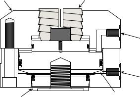
About Series 646 Hydraulic Collet Grips
The Series 646 Hydraulic Collet Grips are mounted in a load unit to secure the specimen under test. Hydraulic pressure to the grips is supplied by an external hydraulic grip supply.
Grip Housing |
Collet |
|
|
Hydraulic |
|
Release |
|
Port |
|
Hydraulic |
|
Pressure |
|
Port |
Grip Piston |
Preload Chamber |
Grip Cross Section
About Gripping Specimens
The grips provide a constant, hydraulically actuated gripping force regardless of the applied test loads. When hydraulic pressure is applied, it pulls the grip housing towards the piston, forcing the collet to clamp the specimen. The pressure applied to the preload chamber locks all moving grip parts in position. This eliminates backlash when cycling between tension and compression.
The specimen gripping force is adjustable to prevent specimen damage by the grips or specimen slippage during the test. Each grip (upper and lower) is independently actuated.
Collet Sets
The grips require collet inserts to accommodate the type of specimen. Various specimen geometries may be easily accommodated by changing only the collet sets. Three types of collets are available; round, flat, and threaded.
Spiral Washers
The optional Model 601 Spiral Washers are commonly used when installing axial grips. They provide fatigue-resistant connections between elements of the force train and minimize the effects of backlash.
The spiral washers are placed over the connector studs and adjusted to place a constant preload on the stud. The spiral washers also minimize the possibility of backlash due to loose-fitting or worn stud threads. When cyclic loads below the tensile force level of the preload are applied to the connections, the load is
16 |
Introduction |
Series 646 Hydraulic Collet Grips |

distributed between the surfaces of the spiral washers and the stud in a ratio of the relative stiffness of the parts. The spiral washers have a large surface area and therefore greater stiffness. They react to most of the load and keep the stress in the stud below its fatigue runout level.
Couplings
Special upper and lower couplings clamp the grips to the actuator and force transducer for axial-torsional grips. Each coupling has two different thread patterns; a right hand thread with a pitch of 3 mm and a left hand thread with a 2 mm pitch. Half of the coupling matches the thread of the grip and the other half matches the thread of the actuator or force transducer adapter. Each coupling is marked to indicate which direction to tighten it and how much torque to lock it down.
Series 646 Hydraulic Collet Grips |
Introduction |
17 |

Specifications
Specifications
Contents |
Series 646 |
Hydraulic Collet Grips Dimensions 18 |
|
Series 646 |
Hydraulic Collet Grips Force and Torque Capacities 20 |
|
Series 646 |
Hydraulic Collet Grips Specifications—Round Specimens 22 |
|
Series 646 |
Hydraulic Collet Grips Specifications—Flat Specimens 23 |
Series 646 Hydraulic Collet Grips Specifications—Threaded Specimens 24
Series 646 Hydraulic Collet Grips Dimensions
The following sections provide the dimensions of the Series 646 Hydraulic Collet
Grips.
Series 646 Collet Grip Dimensions
MODEL |
|
A |
B |
C |
CONNECTOR STUD |
|
|
|
|
|
|
646.10 |
Axial |
107.4 mm |
171.5 mm |
4.0–7.2 mm |
M27 x 2 |
|
|
(4.23 in) |
(6.75 in) |
(0.16–0.28 in) |
(1-14) |
|
|
|
|
|
|
646.25 |
Axial |
171.7 mm |
254 mm |
4.6–9.4 mm |
36 x 2 |
|
|
(6.76 in) |
(10.0 in) |
(0.18–0.37 in) |
(1 1/2-12) |
|
|
|
|
|
|
646.10 |
Axial/Torsional |
107.4 mm |
171.5 mm |
36.5–39.6 mm |
M68 x 2* |
|
|
(4.23 in) |
(6.75 in) |
(1.44–1.56 in) |
- |
|
|
|
|
|
|
646.25 |
Axial/Torsional |
171.7 mm |
254 mm |
54.1–58.9 mm |
M92 x 3* |
|
|
(6.76 in) |
(10.0 in) |
(2.13–2.32 in) |
- |
*Left Handed Threads
18 |
Introduction |
Series 646 Hydraulic Collet Grips |

Specifications
Model 646 Grip with Furnace Extensions Dimensions
Mounting holes in the base of each grip are threaded in either SI International (millimeter) or U.S. Customary (inch) thread dimensions, as shown for dimension “A” in the pervious table.
PARAMETER |
DIMENSION* |
A (mounting threads) |
M27 x 2mm or 1 in–14 |
|
|
B |
172 mm (6.77 in) |
|
|
C |
224 mm (8.80 in) |
|
|
D |
115 mm (4.52 in) |
|
|
E (wrench flats) |
29 mm (1.125 in) |
|
|
F (travel) |
3.2 mm (0.125 in) |
|
|
G (specimen adapter wrench flats) |
32 mm (1.25 in) |
|
|
H (maximum diameter) |
38 mm (1.5 in) |
|
|
Weight (each grip) |
18.5 kg (40.8 lb) |
*SI International (U.S. Customary)
|
|
|
|
|
|
|
|
|
|
|
|
|
|
|
19 |
|
|
|
|
|
|
|
|
|
|
|
|
|
|
|
|
|
|
|
|
|
|
|
|
|
|
|
|
|
|
|
|
|
|
|
|
|
|
|
|
|
|
|
|
|
|
|
|
|
|
|
|
|
|
|
|
|
|
|
|
|
|
|
|
|
|
|
|
|
|
|
|
|
|
|
|
|
|
|
|
|
|
|
|
|
|
|
|
|
|
|
|
|
|
|
|
|
|
|
|
|
|
|
|
|
|
|
|
|
|
|
|
|
|
|
|
|
|
|
|
|
|
|
|
|
|
|
|
|
|
|
|
|
|
|
|
|
|
|
|
|
|
|
|
|
|
|
|
|
|
|
|
|
|
|
|
|
|
|
|
|
|
|
|
|
|
|
|
|
|
|
|
|
|
|
|
|
|
|
|
|
|
|
|
|
|
|
|
|
|
|
|
|
|
|
|
|
|
|
|
|
|
|
|
|
|
|
|
|
|
|
|
|
|
|
|
|
|
|
|
|
|
|
|
|
|
|
|
|
|
|
|
|
|
|
|
|
|
|
|
|
|
|
|
|
|
|
|
|
|
|
|
|
|
|
|
|
|
|
|
|
|
|
|
|
|
|
|
|
|
|
|
Series 646 Hydraulic Collet Grips |
|
|
|
|
|
|
Introduction |
||||||||
|
|
|
|
|
|
||||||||||

Specifications
Series 646 Hydraulic Collet Grips Force and Torque Capacities
The amount of torque the grips can produce is reduced with biaxial operation. The amount of torque is affected by the amount of axial force and the size of the specimen. The following graphs illustrate the axial-torsional performance envelope of the Model 646.10 and Model 646.25 Hydraulic Collet Grips.
Series 646 Collet Grip Specifications
MODEL |
|
AXIAL CAPACITY* |
TORSIONAL CAPACITY* |
WEIGHT |
646.10 |
Axial |
100 kN (22 kip) |
– |
18 kg (40 lb) |
|
|
|
|
|
646.25 |
Axial |
250 kN (55 kip) |
– |
72 kg (160 lb) |
|
|
|
|
|
646.10 |
Axial/Torsional |
100 kN (22 kip) |
1100 N·m (10,000 lbf·in) |
18 kg (40 lb) |
|
|
|
|
|
646.25 |
Axial/Torsional |
250 kN (55 kip) |
2200 N·m (20,000 lbf·in) |
72 kg (160 lb) |
*Ratings are at 45 MPa (6500 psi).
|
10000 |
|
|
|
|
|
|
|
|
|
|
|
9000 |
|
|
|
|
|
|
|
|
|
Specimen |
|
|
|
|
|
|
|
|
|
|
|
|
|
8000 |
|
|
|
|
|
|
|
|
|
Diameter |
|
|
|
|
|
|
|
|
|
|
|
|
|
7000 |
|
|
|
|
|
|
|
|
|
6 mm dia |
|
|
|
|
|
|
|
|
|
|
.25" dia |
|
|
|
|
|
|
|
|
|
|
|
|
|
(in-lbs) |
6000 |
|
|
|
|
|
|
|
|
|
.375 " dia |
|
|
|
|
|
|
|
|
|
15 mm dia |
||
|
|
|
|
|
|
|
|
|
|
|
.5" dia |
Torque |
5000 |
|
|
|
|
|
|
|
|
|
.75" dia |
|
|
|
|
|
|
|
|
|
|
||
|
|
|
|
|
|
|
|
|
|
|
|
|
4000 |
|
|
|
|
|
|
|
|
|
20 mm dia |
|
|
|
|
|
|
|
|
|
|
|
1" dia |
|
3000 |
|
|
|
|
|
|
|
|
|
30 mm dia |
|
2000 |
|
|
|
|
|
|
|
|
|
|
|
1000 |
|
|
|
|
|
|
|
|
|
|
|
0 |
|
|
|
|
|
|
|
|
|
|
|
2000 |
4000 |
6000 |
8000 |
10000 |
12000 |
14000 |
16000 |
18000 |
20000 |
22000 |
Force (lbs)
Model 646.10 Maximum Torque versus Axial Load
20 |
Introduction |
Series 646 Hydraulic Collet Grips |
Specifications
|
20000 |
|
|
|
|
|
|
|
|
|
Specimen |
|
|
|
|
|
|
|
|
|
|
|
|
|
|
|
|
|
|
|
|
|
|
|
Diameter |
|
15000 |
|
|
|
|
|
|
|
|
|
.25 " dia |
|
|
|
|
|
|
|
|
|
|
.375" dia |
|
|
|
|
|
|
|
|
|
|
|
|
|
lbs) |
|
|
|
|
|
|
|
|
|
|
.5" dia |
|
|
|
|
|
|
|
|
|
|
.75" dia |
|
- |
|
|
|
|
|
|
|
|
|
|
20 mm dia |
(in |
10000 |
|
|
|
|
|
|
|
|
|
|
|
|
|
|
|
|
|
|
|
|
||
Torque |
|
|
|
|
|
|
|
|
|
|
|
|
|
|
|
|
|
|
|
|
|
|
|
|
5000 |
|
|
|
|
|
|
|
|
|
|
|
0 |
|
|
|
|
|
|
|
|
|
|
|
2000 |
4000 |
6000 |
8000 |
10000 |
12000 |
14000 |
16000 |
18000 |
20000 |
22000 |
Force (lbs)
Model 646.25 Maximum Torque versus Axial Load
Note The Series 646.25 Axial-Torsional Grips are capable of holding full torque and full load with specimen sizes greater than 24.6 mm (0.97 in).
Series 646 Hydraulic Collet Grips |
Introduction |
21 |
Loading...