


 Loading...
m
be certain.
Series 609 Alignment Fixture
Product Information
015-031-901 E

Copyright information Trademark information
Publication information
© 1993, 1999, 2001, 2008 MTS Systems Corporation. All rights reserved.
MTS is a registered trademark of MTS Systems Corporation within the United States. This trademark may be protected in other countries.
Manual Part Number |
Publication Date |
|
|
150319-01 A |
August 1993 |
|
|
015-031-901 B |
September 1999 |
|
|
015-031-901 C |
February 2001 |
|
|
015-031-901 D |
November 2001 |
|
|
015-031-901 E |
March 2008 |
|
|
2 |
Manual Template 4.3 |

Contents
Technical Support |
5 |
|
|
|
How to Get Technical Support |
5 |
|||
Before You Contact MTS |
5 |
|
||
If You Contact MTS by Phone |
6 |
|||
Problem Submittal Form in MTS Manuals 7 |
||||
Preface 9 |
|
|
|
|
|
|
|
||
Before You Begin 9 |
|
|
||
Conventions |
10 |
|
|
|
Documentation Conventions |
10 |
|||
Introduction |
13 |
|
|
|
|
|
|
|
|
Misalignment |
15 |
|
|
|
About Concentric Misalignment 15 |
||||
Adjust Concentric Alignment |
16 |
|||
About Angular Misalignment |
17 |
|||
Adjust Angular Alignment |
18 |
|||
Safety Information |
21 |
|
|
|
|
|
|||
Hazard Placard Placement |
21 |
|||
Installation |
23 |
|
|
|
|
|
|
|
|
Series 609 Alignment Fixture Product Information |
Contents |
3 |

Specimen Preparation |
29 |
|
|
|
|
|
|
|
About Gaged Specimens 29 |
|
|
|
|
|
|
|
|
Round Thick Diameter Specimens |
31 |
|
|
|
|
|
||
Calculating Bending Strain—Round Thick Diameter Specimens |
32 |
|
||||||
Round Thin Diameter Specimens |
34 |
|
|
|
|
|
||
Calculating Bending Strain—Round Thin Diameter Specimens |
35 |
|
||||||
Flat Thick Specimens |
37 |
|
|
|
|
|
|
|
Calculating Bending Strain—Flat Thick Specimens |
38 |
|
|
|
||||
Flat Thin Specimens |
40 |
|
|
|
|
|
|
|
Calculating Bending Strain—Flat Thin Specimens |
41 |
|
|
|
||||
Notched Round Thick Diameter Specimens |
42 |
|
|
|
|
|||
Calculating Bending Strain—Notched Round Thick Diameter Specimens |
43 |
|||||||
Notched Round Thin Diameter Specimens |
44 |
|
|
|
|
|||
Calculating Bending Strain—Notched Round Thin Diameter Specimens |
45 |
|||||||
Notched Flat Thick Specimens |
48 |
|
|
|
|
|
||
Calculating Bending Strain—Notched Flat Thick Specimens |
49 |
|
|
|||||
Notched Thin Flat Specimens |
51 |
|
|
|
|
|
|
|
Calculating Bending Strain—Notched Thin Flat Specimens |
52 |
|
|
|||||
Alignment Procedure |
55 |
|
|
|
|
|
|
|
|
|
|
|
|
|
|
|
|
Installing a Gaged Specimen |
56 |
|
|
|
|
|
|
|
Adjust the Concentric Alignment |
58 |
|
|
|
|
|
||
Adjust the Angular Alignment |
63 |
|
|
|
|
|
|
|
Check the Alignment |
67 |
|
|
|
|
|
|
|
4 |
Contents |
Series 609 Alignment Fixture Product Information |

How to Get Technical Support
Technical Support
How to Get Technical Support
Start with your manuals
Technical support methods
MTS web site
www.mts.com
Telephone
Fax
The manuals supplied by MTS provide most of the information you need to use and maintain your equipment. If your equipment includes MTS software, look for online help and README files that contain additional product information.
If you cannot find answers to your technical questions from these sources, you can use the internet, e-mail, telephone, or fax to contact MTS for assistance.
MTS provides a full range of support services after your system is installed. If you have any questions about a system or product, contact MTS in one of the following ways.
The MTS web site gives you access to our technical support staff by means of a Technical Support link:
www.mts.com > Contact Us > Service & Technical Support
techsupport@mts.com
MTS Call Center 800-328-2255
Weekdays 7:00 A.M. to 5:00 P.M., Central Time
952-937-4515
Please include “Technical Support” in the subject line.
Before You Contact MTS
Know your site number and system number
MTS can help you more efficiently if you have the following information available when you contact us for support.
The site number contains your company number and identifies your equipment type (material testing, simulation, and so forth). The number is usually written on a label on your MTS equipment before the system leaves MTS. If you do not have or do not know your MTS site number, contact your MTS sales engineer.
Example site number: 571167
When you have more than one MTS system, the system job number identifies which system you are calling about. You can find your job number in the papers sent to you when you ordered your system.
Example system number: US1.42460
Series 609 Alignment Fixture Product Information |
Technical Support |
5 |
If You Contact MTS by Phone
Know information from If you have contacted MTS about this problem before, we can recall your file. prior technical You will need to tell us the:
assistance
•MTS notification number
•Name of the person who helped you
Identify the problem Describe the problem you are experiencing and know the answers to the following questions:
•How long and how often has the problem been occurring?
•Can you reproduce the problem?
•Were any hardware or software changes made to the system before the problem started?
Know relevant computer information
•What are the model numbers of the suspect equipment?
•What model controller are you using (if applicable)?
•What test configuration are you using?
If you are experiencing a computer problem, have the following information available:
•Manufacturer’s name and model number
Know relevant software information
•Operating software type and service patch information
•Amount of system memory
•Amount of free space on the hard drive in which the application resides
•Current status of hard-drive fragmentation
•Connection status to a corporate network
For software application problems, have the following information available:
•The software application’s name, version number, build number, and if available, software patch number. This information is displayed briefly when you launch the application, and can typically be found in the “About” selection in the “Help” menu.
•It is also helpful if the names of other non-MTS applications that are running on your computer, such as anti-virus software, screen savers, keyboard enhancers, print spoolers, and so forth are known and available.
If You Contact MTS by Phone
Your call will be registered by a Call Center agent if you are calling within the United States or Canada. Before connecting you with a technical support specialist, the agent will ask you for your site number, name, company, company address, and the phone number where you can normally be reached.
6 |
Technical Support |
Series 609 Alignment Fixture Product Information |
Problem Submittal Form in MTS Manuals
Identify system type
Be prepared to troubleshoot
Write down relevant information
After you call
If you are calling about an issue that has already been assigned a notification number, please provide that number. You will be assigned a unique notification number about any new issue.
To assist the Call Center agent with connecting you to the most qualified technical support specialist available, identify your system as one of the following types:
•Electromechanical materials test system
•Hydromechanical materials test system
•Vehicle test system
•Vehicle component test system
•Aero test system
Prepare yourself for troubleshooting while on the phone:
•Call from a telephone when you are close to the system so that you can try implementing suggestions made over the phone.
•Have the original operating and application software media available.
•If you are not familiar with all aspects of the equipment operation, have an experienced user nearby to assist you.
Prepare yourself in case we need to call you back:
•Remember to ask for the notification number.
•Record the name of the person who helped you.
•Write down any specific instructions to be followed, such as data recording or performance monitoring.
MTS logs and tracks all calls to ensure that you receive assistance and that action is taken regarding your problem or request. If you have questions about the status of your problem or have additional information to report, please contact MTS again and provide your original notification number.
Problem Submittal Form in MTS Manuals
Use the Problem Submittal Form to communicate problems you are experiencing with your MTS software, hardware, manuals, or service which have not been resolved to your satisfaction through the technical support process. This form includes check boxes that allow you to indicate the urgency of your problem and your expectation of an acceptable response time. We guarantee a timely response—your feedback is important to us.
The Problem Submittal Form can be accessed:
•In the back of many MTS manuals (postage paid form to be mailed to MTS)
•www.mts.com > Contact Us > Problem Submittal Form (electronic form to be e-mailed to MTS)
Series 609 Alignment Fixture Product Information |
Technical Support |
7 |
Problem Submittal Form in MTS Manuals
8 |
Technical Support |
Series 609 Alignment Fixture Product Information |

Before You Begin
Preface
Before You Begin
Safety first!
Other MTS manuals
Before you attempt to use your MTS product or system, read and understand the Safety manual and any other safety information provided with your system. Improper installation, operation, or maintenance of MTS equipment in your test facility can result in hazardous conditions that can cause severe personal injury or death and damage to your equipment and specimen. Again, read and understand the safety information provided with your system before you continue. It is very important that you remain aware of hazards that apply to your system.
In addition to this manual, you may receive additional MTS manuals in paper or electronic form.
If you have purchased a test system, it may include an MTS System Documentation CD. This CD contains an electronic copy of the MTS manuals that pertain to your test system, including hydraulic and mechanical component manuals, assembly drawings and parts lists, and operation and preventive maintenance manuals. Controller and application software manuals are typically included on the software CD distribution disc(s).
Series 609 Alignment Fixture Product Information |
Preface |
9 |

Conventions
Conventions
Documentation Conventions
Hazard conventions
Notes
Special terms
Illustrations
Electronic manual conventions
The following paragraphs describe some of the conventions that are used in your MTS manuals.
As necessary, hazard notices may be embedded in this manual. These notices contain safety information that is specific to the task to be performed. Hazard notices immediately precede the step or procedure that may lead to an associated hazard. Read all hazard notices carefully and follow the directions that are given. Three different levels of hazard notices may appear in your manuals. Following are examples of all three levels.
Note For general safety information, see the safety information provided with your system.

 DANGER
Danger notices indicate the presence of a hazard with a high level of risk which, if ignored, will result in death, severe personal injury, or substantial property damage.

 WARNING
Warning notices indicate the presence of a hazard with a medium level of risk which, if ignored, can result in death, severe personal injury, or substantial property damage.

 CAUTION
Caution notices indicate the presence of a hazard with a low level of risk which, if ignored, could cause moderate or minor personal injury, equipment damage, or endanger test integrity.
Notes provide additional information about operating your system or highlight easily overlooked items. For example:
Note Resources that are put back on the hardware lists show up at the end of the list.
The first occurrence of special terms is shown in italics.
Illustrations appear in this manual to clarify text. It is important for you to be aware that these illustrations are examples only and do not necessarily represent your actual system configuration, test application, or software.
This manual is available as an electronic document in the Portable Document File (PDF) format. It can be viewed on any computer that has Adobe Acrobat Reader installed.
10 |
Preface |
Series 609 Alignment Fixture Product Information |
Documentation Conventions
Hypertext links The electronic document has many hypertext links displayed in a blue font. All blue words in the body text, along with all contents entries and index page numbers, are hypertext links. When you click a hypertext link, the application jumps to the corresponding topic.
Series 609 Alignment Fixture Product Information |
Preface |
11 |
Documentation Conventions
12 |
Preface |
Series 609 Alignment Fixture Product Information |
Introduction
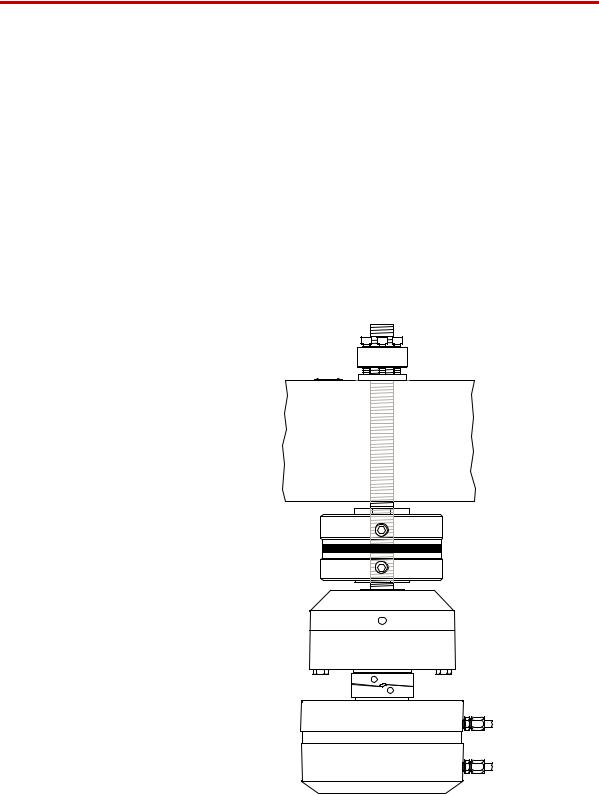
The MTS Series 609 Alignment Fixture improves alignment between the upper and lower grips of your load unit. Improving alignment reduces bending strains in your specimen, which produces more accurate test results. This section discusses the consequences of having misaligned grips and the two types of adjustments that can compensate for misalignment problems:
•One set of adjustments compensates for concentric misalignment.
•One set of adjustments compensates for angular misalignment.
In a typical installation, the Series 609 Alignment Fixture is installed between the force transducer and crosshead.
Contents Misalignment 15
About Concentric Misalignment 15
About Angular Misalignment 17
A 0
 Force Capacity
C 0
Model 609 Alignment Fixture
Series 609 Alignment Fixture Product Information |
Introduction |
13 |
What you need to know
Related products
MTS Systems Corporation assumes that you know how to use your controller. See the appropriate manual for information about performing any controllerrelated step in the procedures in this manual. You are expected to know how to do the following procedures:
•Turn hydraulic pressure on and off.
•Select a control mode.
•Manually adjust the actuator position.
•Install a specimen.
•Define a simple test.
•Run a test.
The Series 609 Alignment Fixture is related to other products. See the following product information manuals for product-specific information and procedures.
•Your load unit manual has information about installing the force transducer.
•Your grip manual has information about installing the grips.
•An option for the alignment fixture is an alignment software package which is used with the fixture. See the Using 709 Easy Alignment manual.
14 |
Introduction |
Series 609 Alignment Fixture Product Information |
Misalignment
Misalignment
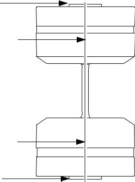
In uniaxial testing, perfectly aligned grips produce uniform axial tensile strains in a specimen. For grips to be perfectly aligned, their loading axes must be concentric.
Mounting Surface
Loading Axis
Equal Strain |
|
|
|
Equal Strain |
||||||
|
|
|
|
|
|
|
|
|
|
|
|
|
|
|
|
|
|
|
|
|
|
|
|
|
|
|
|
|
|
|
|
|
Loading Axis
Mounting Surface
Perfectly Aligned Grips Produce Uniform Axial Strains
Misalignment between the grips produces nonuniform axial strains in a specimen. Some areas will have higher than average strains; other areas lower than average strains. Bending strain is the difference between the average strain and areas with higher or lower than average strains.
Many ASTM procedures limit maximum bending strains because they cause specimens to exhibit much lower strengths than if all axial strains were uniform.
The alignment fixture lets you reduce bending strains by improving concentric and angular alignment between the upper and lower grips.
Grips can have concentric and angular misalignments. Both can occur together and have a combined effect on the bending strains that appear in the specimen.
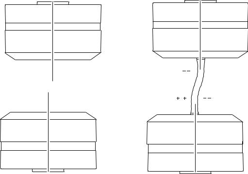
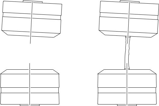
About Concentric Misalignment
Concentric misalignment shifts the vertical axes of the grips laterally away from each other. This puts an “S” shaped bend in the specimen.
A specimen with an “S” bend has a zero bending strain in the middle of its gage section. It has higher than average bending strains at the top and bottom of its
Series 609 Alignment Fixture Product Information |
Introduction |
15 |
Adjust Concentric Alignment
gage section. These higher strains are on opposite sides. It also has lower than average bending strains at the top and bottom of its gage section, opposite the higher strains.
Actual strain readings vary with the amount of tensile load applied to the specimen. With zero or low tensile force applied to the specimen, tensile strain readings can be opposite compressive strain readings. Under higher tensile force, high tensile readings can be opposite lower tensile readings.

 Higher Than Average Strain
Lower Than Average Strain
Concentric Misalignment Produces an “S” Bend
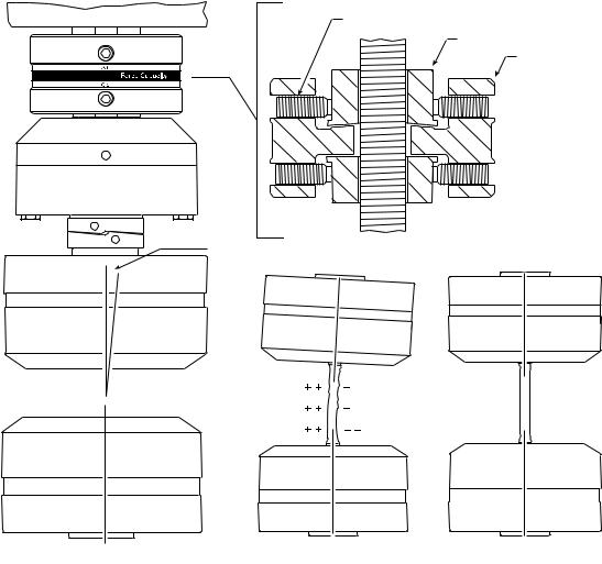
Adjust Concentric Alignment
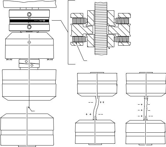
Turning the four lower adjustment screws moves the concentricity collar. Moving the collar laterally shifts the upper grip’s position. This aligns the grips’ centerlines, improving their concentric alignment.
The effect of improved concentricity on a specimen is to reduce its “S” bend and the strains that go with this bend.
As “S” bend strains fade into the background, “C” bend strains come to the foreground. (Remember that concentric and angular misalignment can occur together, putting “S” and “C” bends into the same specimen.)
For many test procedures, removing the “S” bend alone may be enough to get your bending strains within specifications.
16 |
Introduction |
Series 609 Alignment Fixture Product Information |
About Angular Misalignment

 Concentricity Collar
Concentricity Adjustment Screws
|
Before and After |
|
Misalignment |
Concentric |
|
Adjustment |
||
|
Improving Concentric Alignment
About Angular Misalignment
Angular misalignment angles the upper grip’s loading axis away from the lower grip’s loading axis. This misalignment puts a “C”-shaped bend in the specimen.
A specimen with a “C” bend has a side with higher than average strains and a side opposite with lower than average strains. The bending strain is uniform over the entire gage section.
Again, actual strain readings vary with the amount of tensile load applied to the specimen.
With zero or low tensile force applied to the specimen, you can have tensile readings on one side of the specimen and compressive strain readings on the other side of the specimen.
Under higher tensile force, you can have higher tensile readings on one side of the specimen and lower tensile readings on the other side of the specimen.
Series 609 Alignment Fixture Product Information |
Introduction |
17 |
Adjust Angular Alignment
+ + |
– |
+ + |
– |
+ + |
– – |
Angular Misalignment Produces a “C” Bend
Adjust Angular Alignment
Turning the four upper adjustment screws against the angularity collar moves the housing. The mating surfaces of the angularity collar and housing are spherical. This tilts the housing as it moves. This tilt gets the grips’ faces parallel, improving their angular alignment.
Improved angularity reduces the specimen’s “C” bend and the strains that go with this bend.
Removing the “C” bend can create another “S” bend which may need to be reduced.
You may have to go back and forth between reducing the “S” bend and reducing the “C” bend to get the bending strain within specifications.
18 |
Introduction |
Series 609 Alignment Fixture Product Information |
Adjust Angular Alignment
Angularity Adjustment Screws
Angularity Collar
Housing
Misalignment
Equal |
|
|
|
|
|
Equal |
Strain |
|
|
|
|
|
Strain |
|
|
|
|
|
|
|
|
|
|
|
|
|
|
|
|
|
|
|
|
|
Before and After Angular Adjustment
Improving Angular Alignment
Series 609 Alignment Fixture Product Information |
Introduction |
19 |
Adjust Angular Alignment
20 |
Introduction |
Series 609 Alignment Fixture Product Information |
Hazard Placard Placement
Safety Information
Hazard Placard Placement
Hazard placards contain specific safety information and are affixed directly to the system so they are plainly visible.
Each placard describes a system-related hazard. When possible, international symbols (icons) are used to graphically indicate the type of hazard and the placard label indicates its severity. In some instances, the placard may contain text that describes the hazard, the potential result if the hazard is ignored, and general instructions about how to avoid the hazard.
The following labels are typically located on the alignment fixture.
LABEL |
DESCRIPTION |
Model No. |
|
Serial No. |
|
Part No. |
|
|
Rev. |
PN 491909-01
Part # 049-190-901
Alignment Fixture ID label.
Contains the following information:
•Model number
•Part number
•Serial Number
•Revision
MTS Systems Corporation
14000 Technology Drive PN 491906-01
Eden Prairie, MN USA 55344
609 Alignment Fixture |
Force Capacity: |
100 kN / 22 kip |
Model No. |
|
Serial No. |
Part No. |
|
Rev. |
Part # 049-190-601
Alternate ID label.
Contains the following information:
• Model number
• Part number
• Serial Number
• Revision
Series 609 Alignment Fixture Product Information |
Safety Information |
21 |
Loading...