


315
Table of contents
 Loading...
Series 315 Load Frame
Product Information Manual
Model 315.01
Model 315.02
Model 315.03
Model 315.04
l
100-104-403 A

Copyright information © 2002 MTS Systems Corporation. All rights reserved.
Trademark information MTS is a registered trademark of MTS Systems Corporation.
Contact information MTS Systems Corporation
14000 Technology Drive
Eden Prairie, Minnesota 55344-2290 USA
Toll Free Phone: 800-328-2255 (within the U.S. or Canada)
Phone: 952-937-4000 (outside the U.S. or Canada)
Fax: 952-937-4515
E-mail: info@mts.com
http://www.mts.com
Publication information
Manual Part Number Publication Date
100-104-403 A
November 2002

Contents
Introduction 5
Component Identification 7
Functional Description 8
Specifications 10
Load Frame Dimensions 11
Floor Loading Footprint Dimensions 13
Load Frame Stiffness Calculation 14
Installation 17
Lifting and Moving Instructions 18
Connecting Cables 23
Connecting Hydraulics 24
Operation 25
Emergency Stop 25
Crush Point Hazards 26
Maintenance 27
Maintenance Intervals 28
Making Daily Inspections 29
Minimizing Rust 30
Methods for Various Surfaces 30
Checking the Accumulators’ Precharge 31
Series 315 Load Frame Contents
3

4
Contents
Series 315 Load Frame
Introduction
Contents Component Identification 7
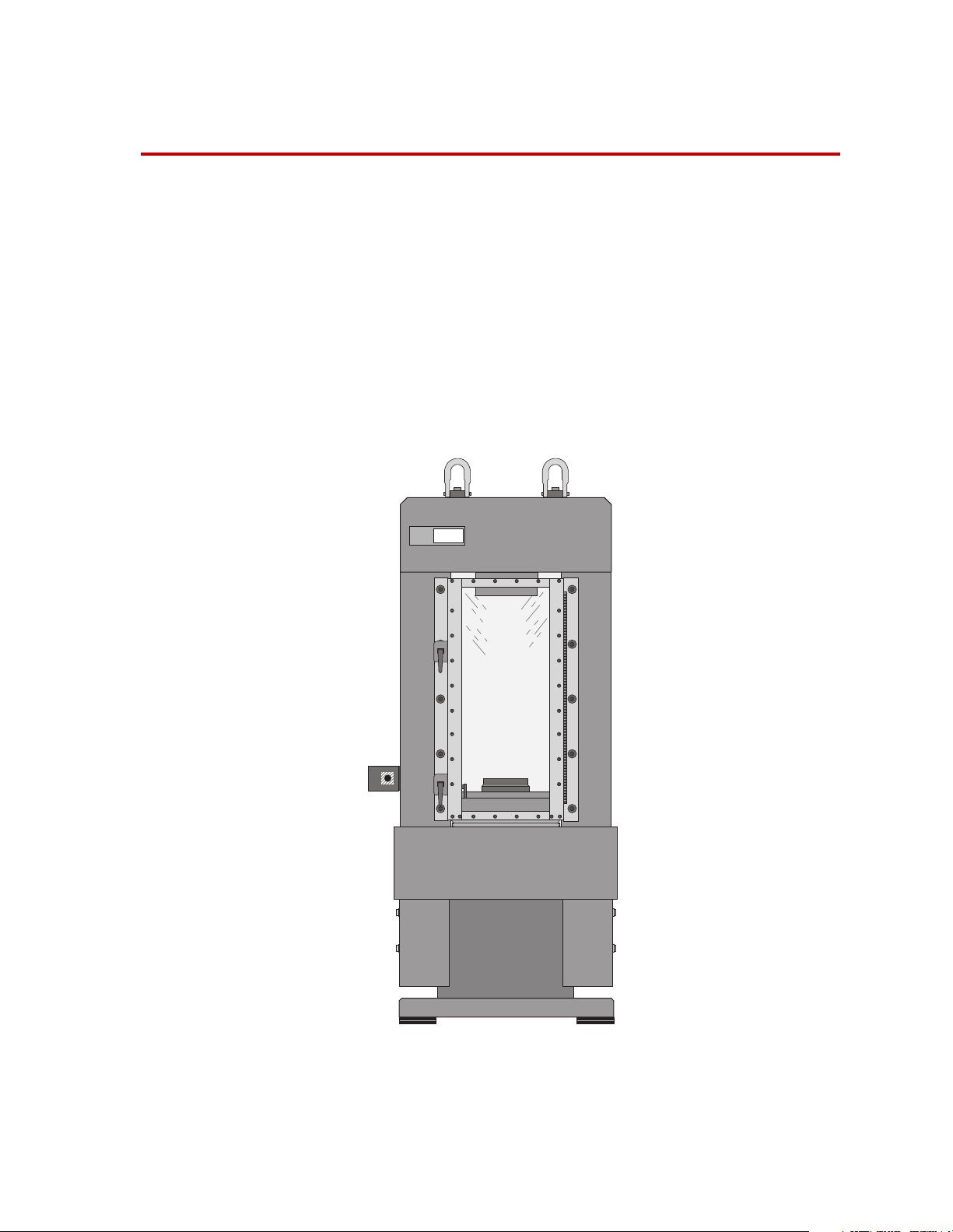
The Series 315 Load Frames are designed to perform high-velocity tension
or compression testing, high-frequency fatigue testing, as well as other
tests. The load frame must be configured with optional actuators,
servovalves, force transducers, grips, and other components from MTS
Systems Corporation.
Functional Description 8
Specifications 10
“Load Frame Stiffness Calculation” on page 14
815
Rock Mechanics
r
Test System
Series 315 Load Frame Introduction
5

What you
need to know
This manual assumes that you know how to use your system controller.
See the appropriate manual for information about performing any
controller-related step in this manual’s procedures. You are expected to
know how to do the following:
• Turn system electrical power on and off
• Turn hydraulic pressure on and off
• Manually adjust the actuator position
• Use your grips and fixtures
Related products The load frame includes other products. See the following product manuals
for product-specific information and maintenance procedures.
• The Series 111 Accumulator Product Information manual.
(part number 011-553-300)
• The Series 252 Servovalve Product Information manual
(part number 011-182-900)
• The Series 298 Actuator Manifold Product Information manual
(part number 011-563-103)
6
Introduction
Series 315 Load Frame
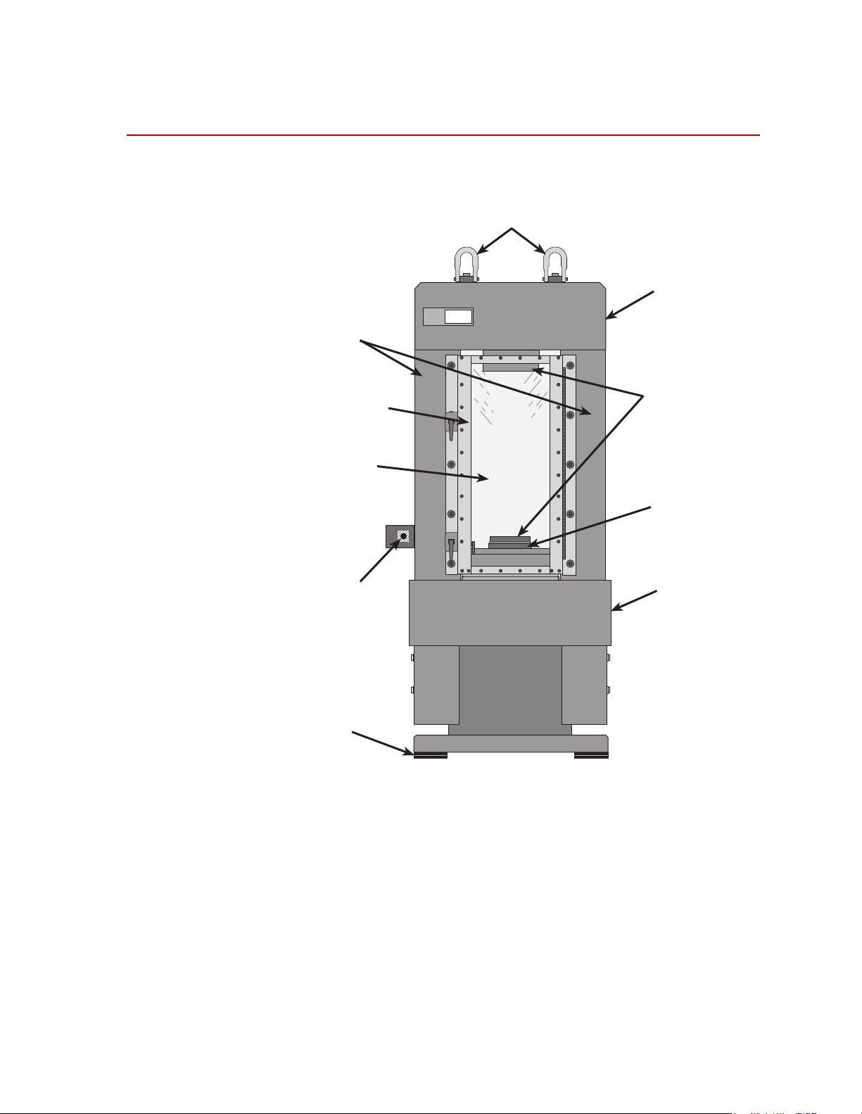
Component Identification
Retangular
Columns
Security
Door
Impact Resistant
Lexan Panel
r
Rock Mechanics
Test System
815
Hoist Rings
Rigid Fixed
Crosshead
Accessory
Attachment
Plates
Fatigue Rated,
Single-ended,
Double-acting
Actuator
Emergency Stop
Button
Vibration
Isolation Pads
Stiff Base
Plate
Series 315 Load Frame Introduction
7

Functional Description
The load frame is a stand alone testing structure. The following paragraphs
describe the components shown on the illustration in the “Component
Identification” on page 7.
Load Frame The load frame has an integrated construction that provides high stiffness,
reducing deflection energy stored in the frame — ideal for testing brittle
materials. The actuator is integrated into the base plate which decreases
frame height and increases stiffness.
The integrated construction also provides a precision, parallel alignment
between crosshead and actuator surface for proper specimen loading.
The load frame provides a large test area for uniaxial and triaxial testing.
The front security door allows easy access to test space. The impact
resistant Lexan panels in front and back allow observation of tests in
progress and helps contain specimen fragments.
Actuator The actuator is a single ended, double acting design allows testing in
compression and tension. The actuator provides a 100 mm (4 in) actuator
stroke for tests requiring large displacements.
Proprietary seal and bearing designs, which have set an industry standard
for durability, ensure long life and performance. Direct-bonded polymer
bearings reduce friction and maximize heat dissipation.
Transducers The load frame usually includes a force transducer and an LVDT (or other
Differential Pressure
∆P) Transducer
(
Internal Linear Variable
Differential Transformer
(LVDT)
displacement measurement device.
The ∆P transducer provides force readout without affecting load frame
stiffness. The ∆P transducer is accurate to within ±1% of the calibrated
range at loads above 1000kN. It provides useful measure of external loads
applied to specimens inside a triaxial cell, when conducting multiple
failure state tests per ISRM. The output signal is conditioned at the Digital
Controller for closed-loop control and data acquisition.
The LVDT is calibrated to full scale actuator travel to provide complete
positioning control. The LVDT is used for specimen positioning and
preloading, and measuring actuator displacement during the test. The
output signal is conditioned at the Digital Controller for closed-loop control
and data acquisition.
8
Introduction
Series 315 Load Frame

Servovalves Servovalves regulate the direction and flow of the hydraulic fluid to and from a
hydraulic actuator. The servovalve responds to the polarity and magnitude of the
command signal generated by the controller.
Hydraulic distribution Hydraulic distribution includes a hydraulic manifold (also called an actuator
manifold or hydraulic service manifold) which controls the hydraulic pressure to the
load frame. The manifold includes solenoid valves that control the hydraulic
pressure (off, low, or high). An actuator manifold is mounted directly to the actuator
on the load frame. A hydraulic service manifold (HSM) is located near the load
frame and connects to the actuator with hydraulic hoses.
Most hydraulic distribution systems will also include a check valve in the return line.
The purpose of this check valve is to minimize actuator drift where pressure is
present on the return line without servo control of the 315 frame.
Series 315 Load Frame Introduction
9

Specifications
Compression rating
kN 1600 2700 4600 4600
kip 350 600 1000 1000
Model 315.01 Model 315.02 Model 315.03 Model 315.04
Tension rating
*
kN 1050 1350 2300 2300
kip 240 300 500 500
Actuator displacement
mm 100 100 100 100
in 4444
Load frame spring rate
†
N/m
lb/in
Parallel alignment between
platens
mm 0.051 0.051 0.051 0.051
in 0.002 0.002 0.002 0.002
Weight
kg 2359 3855 6350 7590
lb 5200 8500 14,000 16,700
7. 0 x 10
4.0 x 10
9
7
9.0 x 10
5.0 x 10
9
7
11.0 x 10
6.3 x 10
9
7
10.5 x 10
6.0 x 10
9
7
Floor Load (using four102 x
152 mm (4 x 6 in.) vibration
isolation pads)
‡
kPa 380 614 1007 1200
psi 55 89 146 174
* Although the Load Frame assembly is capable of producing the indicated force in tension, the actual
tensile force limit is dependent on the attachment hardware (e.g., threaded connectors) that attach
the gripping fixtures to the crosshead and actuator.
† See “Load Frame Stiffness Calculation” on page 14 for the method used to determine load frame
spring rate.
‡ See the figure and table below for the floor loading footprint dimensions.
10
Introduction
Series 315 Load Frame
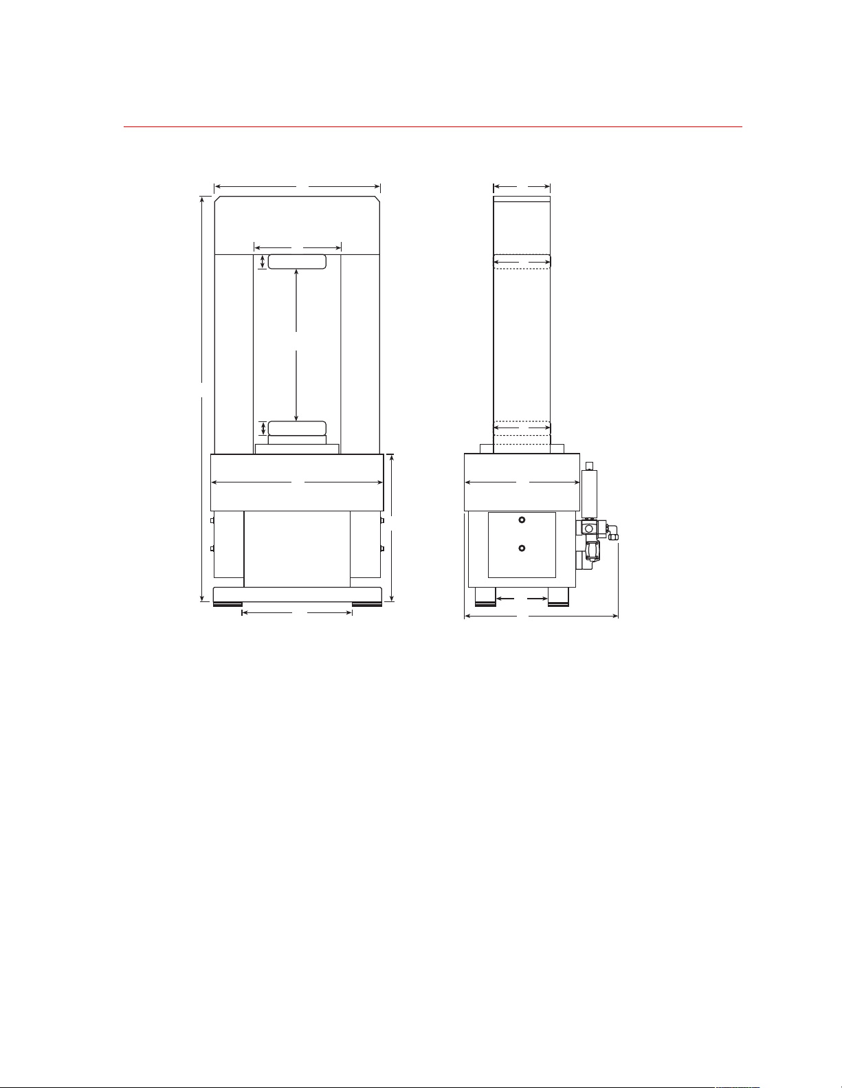
Load Frame Dimensions
D
E
H
J
L
G
A
L
J
B
C
F
M
Model 315 Load Frame Dimensions
N
K
815-315-02
Series 315 Load Frame Introduction
11
Loading...