


 Loading...
m
be certain.
Axial Extensometers
Product Information
100-006-162 E

Copyright information
© 1999, 2000, 2005, 2008, 2009 MTS Systems Corporation. All rights reserved.
Trademark information
|
MTS, TestStar, and TestWare are |
|
|
registered trademarks of MTS Systems |
|
|
Corporation within the United States. |
|
|
These trademarks may be protected in |
|
|
other countries. |
|
Publication information |
|
|
|
|
|
Manual Part Number |
Publication Date |
|
|
|
|
100-006-162 A |
August 1999 |
|
|
|
|
100-006-162 B |
January 2000 |
|
|
|
|
100-006-162 C |
December 2000 |
|
|
|
|
100-006-162 C |
February 2005* |
|
100-006-162 D |
March 2008 |
|
|
|
|
100-006-162 E |
June 2009 |
|
*Format change to smaller size to accommodate packaging. No technical content was changed.

Technical Support 5
How to Get Technical Support 5
Before You Contact MTS 6
If You Contact MTS by Phone 7
Problem Submittal Form in MTS Manuals 9
Preface 11
Before You Begin 11
Documentation Conventions 12
Introduction 15
Axial Extensometer Functional Description 17
About DC Conditioning 17
About Wheatstone Bridge 18
Transducer Calibration 19
Axial Extensometer Overtravel Protection 19
Extensometer Zero Reference 20
Axial Extensometer Accessories 20
Contents |
3 |

Configuration 23
About Quick Attachment Spring Installation 23 How to Install Anchored Springs 24
How to Install an Attachment Adapter 25 How to Install Sliding Springs 26
How to Install Extension Springs or Elastic Bands 30 How to Change Knife Edges 32
About Gage Lengths 35
How to Use Gage Length Extenders 35 How to Use Gage Length De-Extenders 37 How to Connect the Cable 38
Calibration 41
Calibration Overview 41
Certified Calibration 41 Gain 41
Delta K 42
Symmetrical versus Asymmetrical Extensometers 42 How to Use a Vernier Caliper 43
How to Use a Calibration Block 46 How to Use a Calibration Stand 47
Installation 51
Zero Extensometer Output 51
How to Mount an Extensometer 52
About Quick Attachment Springs 53
How to Adjust the Sliding Spring Length 54
How to Select an Anchor Position 56
About Metal Extension Springs 57
Extension Spring Table 58
About Elastic Bands 60
4

Technical Support
How to Get Technical Support
Start with your manuals
The manuals supplied by MTS provide most of the information you need to use and maintain your equipment. If your equipment includes MTS software, look for online help and README files that contain additional product information.
If you cannot find answers to your technical questions from these sources, you can use the internet, e-mail, telephone, or fax to contact MTS for assistance.
Technical support methods
MTS provides a full range of support services after your system is installed. If you have any questions about a system or product, contact MTS in one of the following ways.
MTS web site www.mts.com
The MTS web site gives you access to our technical support staff by means of a Technical Support link:
www.mts.com > Contact Us > Service & Technical Support
techsupport@mts.com
Telephone
MTS Call Center 800-328-2255
Weekdays 7:00 A.M. to 5:00 P.M., Central Time
Fax
952-937-4515
Please include “Technical Support” in the subject line.
Technical Support |
5 |
Before You Contact MTS
MTS can help you more efficiently if you have the following information available when you contact us for support.
Know your site number and system number
The site number contains your company number and identifies your equipment type (material testing, simulation, and so forth). The number is usually written on a label on your MTS equipment before the system leaves MTS. If you do not have or do not know your MTS site number, contact your MTS sales engineer.
Example site number: 571167
When you have more than one MTS system, the system job number identifies which system you are calling about. You can find your job number in the papers sent to you when you ordered your system.
Example system number: US1.42460
Know information from prior technical assistance
If you have contacted MTS about this problem before, we can recall your file. You will need to tell us the:
•MTS notification number
•Name of the person who helped you
Identify the problem
Describe the problem you are experiencing and know the answers to the following questions:
•How long and how often has the problem been occurring?
•Can you reproduce the problem?
•Were any hardware or software changes made to the system before the problem started?
•What are the model numbers of the suspect equipment?
•What model controller are you using (if applicable)?
•What test configuration are you using?
6 |
Technical Support |
Know relevant computer information
If you are experiencing a computer problem, have the following information available:
•Manufacturer’s name and model number
•Operating software type and service patch information
•Amount of system memory
•Amount of free space on the hard drive in which the application resides
•Current status of hard-drive fragmentation
•Connection status to a corporate network
Know relevant software information
For software application problems, have the following information available:
•The software application’s name, version number, build number, and if available, software patch number. This information is displayed briefly when you launch the application, and can typically be found in the “About” selection in the “Help” menu.
•It is also helpful if the names of other non-MTS applications that are running on your computer, such as anti-virus software, screen savers, keyboard enhancers, print spoolers, and so forth are known and available.
If You Contact MTS by Phone
Your call will be registered by a Call Center agent if you are calling within the United States or Canada. Before connecting you with a technical support specialist, the agent will ask you for your site number, name, company, company address, and the phone number where you can normally be reached.
If you are calling about an issue that has already been assigned a notification number, please provide that number. You will be assigned a unique notification number about any new issue.
Technical Support |
7 |
Identify system type
To assist the Call Center agent with connecting you to the most qualified technical support specialist available, identify your system as one of the following types:
•Electromechanical materials test system
•Hydromechanical materials test system
•Vehicle test system
•Vehicle component test system
•Aero test system
Be prepared to troubleshoot
Prepare yourself for troubleshooting while on the phone:
•Call from a telephone when you are close to the system so that you can try implementing suggestions made over the phone.
•Have the original operating and application software media available.
•If you are not familiar with all aspects of the equipment operation, have an experienced user nearby to assist you.
Write down relevant information
Prepare yourself in case we need to call you back:
•Remember to ask for the notification number.
•Record the name of the person who helped you.
•Write down any specific instructions to be followed, such as data recording or performance monitoring.
After you call
MTS logs and tracks all calls to ensure that you receive assistance and that action is taken regarding your problem or request. If you have questions about the status of your problem or have additional information to report, please contact MTS again and provide your original notification number.
8 |
Technical Support |
Problem Submittal Form in MTS Manuals
Use the Problem Submittal Form to communicate problems you are experiencing with your MTS software, hardware, manuals, or service which have not been resolved to your satisfaction through the technical support process. This form includes check boxes that allow you to indicate the urgency of your problem and your expectation of an acceptable response time. We guarantee a timely response—your feedback is important to us.
The Problem Submittal Form can be accessed:
•In the back of many MTS manuals (postage paid form to be mailed to MTS)
•www.mts.com > Contact Us > Problem Submittal Form (electronic form to be e-mailed to MTS)
Technical Support |
9 |
10 |
Technical Support |
Preface
Before You Begin
Safety first!
Before you attempt to use your MTS product or system, read and understand the Safety manual and any other safety information provided with your system. Improper installation, operation, or maintenance of MTS equipment in your test facility can result in hazardous conditions that can cause severe personal injury or death and damage to your equipment and specimen. Again, read and understand the safety information provided with your system before you continue. It is very important that you remain aware of hazards that apply to your system.
Other MTS manuals
In addition to this manual, you may receive additional MTS manuals in paper or electronic form.
If you have purchased a test system, it may include an MTS System Documentation CD. This CD contains an electronic copy of the MTS manuals that pertain to your test system, including hydraulic and mechanical component manuals, assembly drawings and parts lists, and operation and preventive maintenance manuals. Controller and application software manuals are typically included on the software CD distribution disc(s).
Preface |
11 |

Conventions
Documentation Conventions
The following paragraphs describe some of the conventions that are used in your MTS manuals.
Hazard conventions
As necessary, hazard notices may be embedded in this manual. These notices contain safety information that is specific to the task to be performed. Hazard notices immediately precede the step or procedure that may lead to an associated hazard. Read all hazard notices carefully and follow the directions that are given. Three different levels of hazard notices may appear in your manuals. Following are examples of all three levels.
Note For general safety information, see the safety information provided with your system.

 DANGER
Danger notices indicate the presence of a hazard with a high level of risk which, if ignored, will result in death, severe personal injury, or substantial property damage.

 WARNING
Warning notices indicate the presence of a hazard with a medium level of risk which, if ignored, can result in death, severe personal injury, or substantial property damage.

 CAUTION
Caution notices indicate the presence of a hazard with a low level of risk which, if ignored, could cause moderate or minor personal injury, equipment damage, or endanger test integrity.
Notes
Notes provide additional information about operating your system or highlight easily overlooked items. For example:
12 |
Preface |
Note Resources that are put back on the hardware lists show up at the end of the list.
Special terms
The first occurrence of special terms is shown in italics.
Illustrations
Illustrations appear in this manual to clarify text. It is important for you to be aware that these illustrations are examples only and do not necessarily represent your actual system configuration, test application, or software.
Electronic manual conventions
This manual is available as an electronic document in the Portable Document File (PDF) format. It can be viewed on any computer that has Adobe Acrobat Reader installed.
Hypertext links
The electronic document has many hypertext links displayed in a blue font. All blue words in the body text, along with all contents entries and index page numbers, are hypertext links. When you click a hypertext link, the application jumps to the corresponding topic.
Preface |
13 |
14 |
Preface |

Introduction
This manual describes the MTS axial extensometer family. Axial extensometers measure changes along the length of a specimen. Axial extensometers are suitable for a variety of static and dynamic testing applications including tension/compression testing, low and high cycle fatigue, creep/stress relaxation testing, and strain rate testing. Several accessories are available such as gage length extenders, gage length deextenders, knife edges, and attachment methods. Not all accessories are available for all models.
Contents
Axial Extensometer Functional Description 17
Axial Extensometer Accessories 20
l |
|
l |
MODEL |
|
MODEL |
632.11 |
|
|
|
632.13 |
|
|
|
|
l |
lMODEL632.26 |
l |
632.29F-30 |
||
MODEL |
|
Opt. 001 |
632.27 |
|
|
l |
l |
MODEL |
MODEL |
634.12 |
634.31 |
Assorted Extensometers
Introduction |
15 |
What you need to know
This manual assumes that you know how to use your system controller. See the appropriate manual for information about performing any controller-related step in this manual’s procedures. You are expected to know how to:
•Select a control mode.
•Manually adjust the actuator position.
•Zero a sensor output.
•Install a specimen.
Related documentation
This manual covers topics that are common among all axial extensometers. Specific information about a given extensometer is available from the drawings that are included with it.
Each extensometer may include the following documents:
•An installation drawing provides the specifications for your extensometer. It also includes detailed drawings and notes related to setting up and installing the extensometer.
•A Final Inspection card provides information such as the serial number, as tested excitation voltage, and other performance data.
•An Extensometer Calibration Data sheet is included when MTS calibrates the extensometer.
•You may have drawings for optional kits for your extensometer. These drawings include specifications and installation information for the given option.
•You may have a model application drawing that lists the family of extensometers for the model number you purchased. It lists the specification differences among the extensometer family. The drawing also includes the part number of the installation drawing for your extensometer and the wiring diagram of the connector.
This manual is designed to be used with these documents.
16 |
Introduction |
Axial Extensometer Functional Description
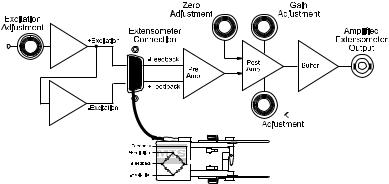
An axial extensometer is a sensor attached to a specimen that measures a dimensional change (gage length or strain) that occurs in the specimen while being tested. Extensometers use a Wheatstone bridge circuit to detect the dimensional changes. Because they are DC devices, they require a DC conditioner for signal processing. The following paragraphs describe the functions of the axial extensometers.
About DC Conditioning
The transducer requires a DC conditioner to process the transducer signal. A DC conditioner provides a DC excitation voltage to the transducer. Any changes to the gage length of the transducer change the excitation signal. The changed signal is output to the DC conditioner as feedback. The DC conditioner processes the signal and makes it available to the controller where the signal may be used.
Typical Conditioning Circuit
Introduction |
17 |
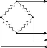
About Wheatstone Bridge
The axial transducer uses precision, resistance-type, foil strain gages bonded to a metallic element to form a Wheatstone bridge. Two knife edges on the transducer arms contact the specimen. Elongation or compression of the specimen causes movement of the transducer arms. This movement bends the metallic element, changing the resistance of the strain gages. The change in the balance of the Wheatstone bridge produces an electrical output that is proportional to the displacement of the transducer arms.
Sensor |
Feedback |
|
Bridge |
||
|
||
|
Excitation |
18 |
Introduction |
Transducer Calibration
The DC conditioner and the transducer signal must be calibrated. Calibration ensures that the transducer signal accurately represents the gage length measure by the transducer. Calibration involves adjusting the excitation voltage and gain of the DC conditioner to achieve the desired transducer signal. The purpose of calibration is to equate a specific transducer displacement to a specific voltage. When the transducer is calibrated, it is matched to a DC conditioner. If either component of the matched pair is changed, recalibration is required.
Axial Extensometer Overtravel Protection
When a specimen fails, the extensometer arms can be subjected to movement beyond the rated travel. Overtravel protection is accomplished with a pair of overtravel blocks. One block limits the tension travel and the other limits the compressive travel to the rated range of the extensometer.
Upper Arm
Overtravel |
Blocks |
Lower Arm
Zero Stop 
Introduction |
19 |
Extensometer Zero Reference
There are three zero reference methods used by MTS’s extensometers: zero pin, zero stop, and fixture. The zero reference position is important when calibrating the extensometer output signal or when mounting an extensometer to a specimen.
Zero pin
Some extensometers includes a zero pin that can be inserted into a zero reference hole. This locks the extensometer arms in the zero reference position. This is useful for specimen installation.
Zero stop
Some extensometers include a zero stop block built into the arms of the extensometer. A zero stop block works like overtravel blocks. When installing a specimen, pinch the two arms of the extensometer together. This stops the extensometer’s arms in the zero position.
Fixture
Some extensometers require special fixtures that set the arms of the extensometer into the proper zero reference positon.
Axial Extensometer Accessories
Note Not all accessories are available for all extensometers. Check with MTS Systems Corporation for a list of possible accessories for your extensometer.
Accessories available for the axial extensometers include the following:
•Gage length extenders increase the gage length of the extensometer without changing its travel. An extension bracket is mounted to one arm of an extensometer to increase the gage length.
•Gage length de-extenders decrease the gage length of the extensometer without changing its travel. De-extender hardware is mounted to both arms of an extensometer to decrease the gage length.
•Cable connectors from the extensometer can be an Amphenol or a PT connector.
•A Model 650.03 Extensometer Calibrator can help with the local calibration of any extensometer.
20 |
Introduction |
Loading...