


 Loading...
MTS Criterion® Series 40
Manual Title
ProductAd itionalInformationInformati
be certain.
100-231-445 C
Copyright information
Trademark information
Proprietary information
Software validation and verification
© 2011 -2014 MTS Systems Corporation. All rights reserved.
MTS and MTS Criterion are registered trademarks of MTS Systems Corporation within the United States. These trademarks may be protected in other countries.
Software use and license is governed by MTS’ End User License Agreement which defines all rights retained by MTS and granted to the End User. All Software is proprietary, confidential, and owned by MTS Systems Corporation and cannot be copied, reproduced, disassembled, decompiled, reverse engineered, or distributed without express written consent of MTS.
MTS software is developed using established quality practices in accordance with the requirements detailed in the ISO 9001 standards. Because MTSauthored software is delivered in binary format, it is not user accessible. This software will not change over time. Many releases are written to be backwards compatible, creating another form of verification.
The status and validity of MTS’ operating software is also checked during system verification and routine calibration of MTS hardware. These controlled calibration processes compare the final test results after statistical analysis against the predicted response of the calibration standards. With these established methods, MTS assures its customers that MTS products meet MTS’ exacting quality standards when initially installed and will continue to perform as intended over time.
Publication information |
MANUAL PART NUMBER |
PUBLICATION DATE |
|
|
|
|
100-231-445 A |
January 2011 |
|
|
|
|
100-231-445 B |
March 2012 |
|
|
|
|
100-231-445 C |
June 2014 |
|
|
|
2 |
MTS Criterion® Series 40 Product Manual |

Contents
Technical Support |
7 |
|
|
|
|
|||
|
|
|
|
|||||
|
How to Get Technical Support |
7 |
|
|||||
|
Before You Contact MTS Service Representative |
7 |
||||||
|
If You Contact MTS by Phone |
8 |
|
|||||
Preface |
11 |
|
|
|
|
|
|
|
|
|
|
|
|
|
|||
|
Before You Begin |
11 |
|
|
|
|||
Conventions |
12 |
|
|
|
|
|
|
|
|
Documentation Conventions |
12 |
|
|||||
Safety |
13 |
|
|
|
|
|
|
|
|
|
|
|
|
||||
|
General Safety Practices |
13 |
|
|
||||
|
Safety Practices Before System Operation 14 |
|
||||||
|
Safety Practices While the System Is in Operation |
17 |
||||||
|
Hazard Labels 18 |
|
|
|
|
|||
Introduction |
|
21 |
|
|
|
|
|
|
|
|
|
|
|
|
|||
|
About This Manual |
21 |
|
|
|
|||
|
Inappropriate Use |
21 |
|
|
|
|||
Description 22 |
|
|
|
|
|
|
||
|
Frame Controller |
22 |
|
|
|
|||
|
Software |
22 |
|
|
|
|
|
|
Load Frame Components |
24 |
|
|
|
|
|||
Specifications |
35 |
|
|
|
|
|
||
Common Specifications |
36 |
|
|
|
||||
Model Specifications |
37 |
|
|
|
|
|||
Dimensions |
45 |
|
|
|
|
|
||
Installation |
55 |
|
|
|
|
|
||
|
|
|
|
|||||
Frame Location and Ventilation |
56 |
|
|
|||||
Leveling the Load Frame |
57 |
|
|
|
|
|||
MTS Criterion® Series 40 Product Manual |
Contents |
3 |

Leveling the Table-Top Load Frame 57 |
|
|
|
|||
Leveling the Floor-Standing Load Frame |
58 |
|
|
|||
Installing Optional Enclosures 59 |
|
|
|
|||
Single-Column Load Frame |
59 |
|
|
|
||
Dual-Column Load Frames |
64 |
|
|
|
||
Controller Connections 69 |
|
|
|
|
||
Connecting the Main Power |
69 |
|
|
|
||
Installing Cables |
70 |
|
|
|
|
|
Accessory Mounting Dimensions |
82 |
|
|
|
||
Model C41 Accessory Mounting Dimensions |
83 |
|
||||
Model C42 Accessory Mounting Dimensions |
84 |
|
||||
Model C43 Accessory Mounting Dimensions |
86 |
|
||||
Model C44 Accessory Mounting Dimensions |
89 |
|
||||
Model C45.504W Accessory Mounting Dimensions 91 |
||||||
Model C45.504/C45.105 Accessory Mounting Dimensions 93 |
||||||
Model C45.305 Accessory Mounting Dimensions |
96 |
|||||
Model C45.605Accessory Mounting Dimensions |
98 |
|||||
Operation 101 |
|
|
|
|
|
|
|
|
|
||||
Main Power Switch (I/O) and Emergency-Stop |
103 |
|
||||
Setting Crosshead Travel Limits |
105 |
|
|
|
||
Crush Zone Hazards |
107 |
|
|
|
|
|
Fixture Mounting |
108 |
|
|
|
|
|
Load Cell Mounting |
109 |
|
|
|
|
|
Handset Control |
114 |
|
|
|
|
|
Maintenance |
117 |
|
|
|
|
|
|
|
|
|
|
|
|
Routine Maintenance Overview Checklist 117
Other service 119
Troubleshooting 121
Decommissioning 123
Appendix 125
Additional Digital I/O Information 125
4 |
Contents |
MTS Criterion® Series 40 Product Manual |

Electromechanical Load Unit Maintenance and Service Logs 127
8 Hours/Daily |
128 |
40 Hours/Weekly 129 |
|
2000 Hours |
130 |
PC Maintenance and System Inspection 130 |
|
2000 Hours |
131 |
System Checks 131 |
|
2000 Hours |
132 |
Lubrication 132 |
|
2000 Hours |
133 |
Frame and Work Area 133
Declaration of Conformity 135
MTS Criterion® Series 40 Product Manual |
Contents |
5 |

How to Get Technical Support
Technical Support
How to Get Technical Support
Start with your manuals
Technical support methods
The manuals supplied by MTS provide most of the information you need to use and maintain your equipment. If your equipment includes software, look for online help and README files that contain additional product information.
If you cannot find answers to your technical questions from these sources, you can use the Internet, e-mail, telephone, or fax to contact MTS for assistance.
MTS provides a full range of support services after your system is installed. If you have any questions about a system or product, contact Technical Support in one of the following ways.
Outside the U.S. For technical support outside the United States, contact your local sales and service office. For a list of worldwide sales and service locations and contact information, use the Global MTS link at the MTS web site:
www.mts.com > About MTS Systems > Global Presence (choose your region in the right-hand column) > (choose the location closest to you)
Before You Contact MTS Service Representative
Know your contact number and system number
Identify the problem
MTS can help you more efficiently if you have the following information available when you contact us for support.
The contact number contains your company number and identifies your equipment type (such as material testing or simulation). The number is typically written on a label on your equipment before the system leaves MTS. If you do not know your MTS contact number, contact your sales engineer.
When you have more than one MTS system, the system model number and series number identifies your system. You can find your these number in your order paperwork or directly on your equipment.
Describe the problem and know the answers to the following questions:
•How long and how often has the problem occurred?
•Can you reproduce the problem?
•Were any hardware or software changes made to the system before the problem started?
•What are the equipment model numbers?
•What is the controller model (if applicable)?
•What is the system configuration?
MTS Criterion® Series 40 Product Manual |
Technical Support |
7 |
If You Contact MTS by Phone
Know relevant |
For a computer problem, have the following information available: |
|
computer information |
• |
Manufacturer’s name and model number |
|
||
|
• |
Operating software type and service patch information |
|
• |
Amount of system memory |
|
• |
Amount of free space on the hard drive where the application resides |
|
• |
Current status of hard-drive fragmentation |
|
• |
Connection status to a corporate network |
Know relevant software information
For software application problems, have the following information available:
•The software application’s name, version number, build number, and (if available) software patch number. This information can typically be found in the About selection in the Help menu.
•The names of other applications on your computer, such as:
–Anti-virus software
–Screen savers
–Keyboard enhancers
–Print spoolers
–Messaging applications
If You Contact MTS by Phone
A Call Center agent registers your call before connecting you with a technical support specialist. The agent asks you for your:
•Contact number
•Name
•Company name
•Company address
•Phone number where you can be reached
If your issue has a notification number, please provide that number. A new issue will be assigned a unique notification number.
8 |
Technical Support |
MTS Criterion® Series 40 Product Manual |
Identify system type
Be prepared to troubleshoot
Write down relevant information
After you call
If You Contact MTS by Phone
To enable the Call Center agent to connect you with the most qualified technical support specialist available, identify your system as one of the following types:
•Electromechanical material test system
•Hydromechanical material test system
•Vehicle test system
•Vehicle component test system
•Aero test system
Prepare to perform troubleshooting while on the phone:
•Call from a telephone close to the system so that you can implement suggestions made over the phone.
•Have the original operating and application software media available.
•If you are not familiar with all aspects of the equipment operation, have an experienced user nearby to assist you.
In case Technical Support must call you:
•Verify the notification number.
•Record the name of the person who helped you.
•Write down any specific instructions.
MTS logs and tracks all calls to ensure that you receive assistance for your problem or request. If you have questions about the status of your problem or have additional information to report, please contact Technical Support again and provide your original notification number.
MTS Criterion® Series 40 Product Manual |
Technical Support |
9 |
Before You Begin
Preface
Before You Begin
Safety first!
Other MTS manuals
Before you use your MTS product or system, read and understand the Safety manual and any other safety information provided with your system. Improper installation, operation, or maintenance can result in hazardous conditions that can cause severe personal injury or death, or damage to your equipment and specimen. Again, read and understand the safety information provided with your system before you continue. It is very important that you remain aware of hazards that apply to your system.
In addition to this manual, you may receive additional manuals in paper or electronic form.
Manuals located on the product information CD will contain information that pertains to your test system, such as:
•Hydraulic and/or mechanical accessory manuals
•Assembly drawings
•Parts lists
•Operation instructions
•Preventive maintenance tasks
Controller and application software manuals are typically included on the software CD distribution disc(s).
MTS Criterion® Series 40 Product Manual |
Preface |
11 |

Conventions
Conventions
Documentation Conventions
Hazard conventions
Notes
Special terms
Illustrations
Electronic manual conventions
Hypertext links
The following paragraphs describe some of the conventions that are used in your MTS manuals.
Hazard notices may be embedded in this manual. These notices contain safety information that is specific to the activity to be performed. Hazard notices immediately precede the step or procedure that may lead to an associated hazard. Read all hazard notices carefully and follow all directions and recommendations. Three different levels of hazard notices may appear in your manuals. Following are examples of all three levels.
Note Refer to “Safety” on page 13 for general safety information.
 DANGER
Danger notices indicate the presence of a hazard with a high level of risk which, if ignored, will result in death, severe personal injury, or substantial property damage.
 WARNING
Warning notices indicate the presence of a hazard with a medium level of risk which, if ignored, can result in death, severe personal injury, or substantial property damage.
 CAUTION
Caution notices indicate the presence of a hazard with a low level of risk which, if ignored, could cause moderate or minor personal injury or equipment damage, or could endanger test integrity.
Notes provide additional information about operating your system or highlight easily overlooked items. For example:
Note Resources that are put back on the hardware lists show up at the end of the list.
The first occurrence of special terms is shown in italics.
Illustrations appear in this manual to clarify text. They are examples only and do not necessarily represent your actual system configuration, test application, or software.
This manual is available as an electronic document in the Portable Document File (PDF) format. It can be viewed on any computer that has Adobe Acrobat Reader installed.
The electronic document has many hypertext links displayed in a blue font. All blue words in the body text, along with all contents entries and index page numbers, are hypertext links. When you click a hypertext link, the application jumps to the corresponding topic.
12 Preface |
MTS Criterion® Series 40 Product Manual |

General Safety Practices
Safety
General Safety Practices
This section provides information about safety issues that pertain to electromechanical systems in general. These issues include statements to the intended use and foreseeable misuse of the system, the hazard zone, definition for the graphical hazard labeling that is affixed to your product, and other (more general) safety information that relates to the high-performance characteristics of MTS Criterion electromechanical systems.
MTS Criterion test systems are designed to generate motions and forces and impart these motions and forces into a test specimen.
When you prepare to operate the system and during system operation, ensure the following:
•Do not use or allow personnel to operate the system who are not experienced, trained, or educated in the inherent dangers associated with high-performance electromechanical machines and who are not experienced, trained, or educated with regard to the intended operation as it applies to this test system.
•Do not disable safety components or features (including limit detectors, light curtains, or proximity switches/detectors).
•Do not attempt to operate the system without appropriate personal safety gear (for example, hearing, hand, and eye protection).
•Do not use specimens that are combustible, flammable, pressurized, or explosive.
•Whenever possible, use tongs or similar device to handle specimens during specimen installation.
•Do not use humans as specimens or allow humans to ride in or on the test specimen or the test system for any purpose unless the system is man-rated and all associated safety conditions are strictly enforced.
•Do not modify the system or replace system components using parts that are not MTS component parts or effect repairs using parts or components that are not manufactured to MTS specifications.
•Do not operate the system in an explosive atmosphere.
•Do not use the system in a test area where uncontrolled access to the test system is allowed when the system is in operation.
If you have system related responsibilities (that is, if you are an operator, service engineer, or maintenance person), you should study safety information carefully before you attempt to perform any test system procedure.
MTS Criterion® Series 40 Product Manual |
Safety 13 |
Safety Practices Before System Operation
You should receive training on this system or a similar system to ensure a thorough knowledge of your equipment and the safety issues that are associated with its use. In addition, you should gain an understanding of system functions by studying the other manuals supplied with your test system. Contact MTS for information about the content and dates of training classes that are offered.
It is very important that you study the following safety information to ensure that your facility procedures and the system’s operating environment do not contribute to or result in a hazardous situation. Remember, you cannot eliminate all the hazards associated with this system, so you must learn and remain aware of the hazards that apply to your system at all times. Use these safety guidelines to help learn and identify hazards so that you can establish appropriate training and operating procedures and acquire appropriate safety equipment (such as gloves, goggles, and hearing protection).
Each test system operates within a unique environment which includes the following known variables:
•Facility variables (facility variables include the structure, atmosphere, and utilities)
•Unauthorized customer modifications to the equipment
•Operator experience and specialization
•Test specimens
Because of these variables (and the possibility of others), your system can operate under unforeseen circumstances that can result in an operating environment with unknown hazards.
Improper installation, operation, or maintenance of your system can result in hazardous conditions that can cause death, personal injury, or damage to the equipment or to the specimen. Common sense and a thorough knowledge of the system’s operating capabilities can help to determine an appropriate and safe approach to its operation.
Safety Practices Before System Operation
Read all manuals
Locate and read hazard placards/labels
Before you apply power to the test system, review and complete all of the safety practices that are applicable to your system. The goal, by doing this, is to improve the safety awareness of all personnel involved with the system and to maintain, through visual inspections, the integrity of specific system components.
Study the contents of this manual and the other manuals provided with your system before attempting to perform any system function for the first time. Procedures that seem relatively simple or intuitively obvious can require a complete understanding of system operation to avoid unsafe or dangerous situations.
Find, read, and follow the hazard placard instructions located on the equipment. These placards are placed strategically on the equipment to call attention to areas such as known crush points and electrical voltage hazards.
14 Safety |
MTS Criterion® Series 40 Product Manual |
Locate lockout/tagout points
Know facility safe procedures
Locate Emergency Stop
buttons
Know controls
Have first aid available
Know potential crush and pinch points
Know electrical hazards
Keep bystanders safely away
Wear proper clothing
Remove flammable fluids from test specimen
Check bolt ratings and torques
Safety Practices Before System Operation
Know where the lockout/tagout point is for all of the supply energies associated with your system. This includes the hydraulic, pneumatic, electric, and water supplies (as appropriate) for your system to ensure that the system is isolated from these energies when required.
Most facilities have internal procedures and rules regarding safe practices within the facility. Be aware of these safe practices and incorporate them into your daily operation of the system.
Know the location of all the system Emergency Stop buttons so that you can stop the system quickly in an emergency. Ensure that an Emergency Stop button is located within 2 meters (6 feet) of the operator at all times.
Before you operate the system for the first time, make a trial run through the operating procedures with the power off. Locate all hardware and software controls and know what their functions are and what adjustments they require. If any control function or operating adjustment is not clear, review the applicable information until you understand it thoroughly.
Accidents can happen even when you are careful. Arrange your operator schedules so that a properly trained person is always close by to render first aid. In addition, ensure that local emergency contact information is posted clearly and in sight of the system operator.
Be aware of potential crush and pinch points on your system and keep personnel and equipment clear of these areas.
When the system electrical power is turned on, minimize the potential for electrical shock hazards. Wear clothing and use tools that are properly insulated for electrical work. Avoid contact with exposed wiring or switch contacts.
Whenever possible, turn off electrical power when you work on or in proximity to any electrical system component. Observe the same precautions as those given for any other high-voltage machinery.
Keep bystanders at a safe distance from all equipment. Never allow bystanders to touch specimens or equipment while the test is running.
Do not wear neckties, shop aprons, loose clothing or jewelry, or long hair that could get caught in equipment and result in an injury. Remove loose clothing or jewelry and restrain long hair.
Remove flammable fluids from their containers or from components before you install the container or component in a test system. If desired, you can replace the flammable fluid with a non-flammable fluid to maintain the proper proportion of weight and balance.
To ensure a reliable product, fasteners (such as bolts and tie rods) used in MTS manufactured systems are torqued to specific requirements. Over torquing or under torquing a fastener can create a hazardous situation due to the high forces and pressures present in MTS test systems.
MTS Criterion® Series 40 Product Manual |
Safety 15 |
Safety Practices Before System Operation
Practice good housekeeping
Protect hoses and cables
Record changes
Provide test area guards
Do not disable safety devices
Use appropriately sized fuses
Provide adequate lighting
Provide means to access out-of-reach components
Ensure equipment is secure
Perodically run consistancy checks
On rare occasions, a fastener can fail even when it is correctly installed. Failure usually occurs during torquing, but it can occur several days later. Failure of a fastener can result in a high velocity projectile. Therefore, it is a good practice to avoid stationing personnel in line with or below assemblies that contain large or long fasteners.
Keep the floors in the work area clean. Do not leave tools, fixtures, or other items not specific to the test, lying about on the floor, system, or decking.
Protect electrical cables from excessive temperatures that can cause the cables to harden and eventually fail. Ensure that all cables have appropriate strain relief devices installed at the cable and near the connector plug. Do not use the connector plug as a strain relief.
Protect all system hoses and cables from sharp or abrasive objects that can cause the hose or cable to fail. Never walk on hoses or cables or move heavy objects over them. Consider system layout and route hoses and cables away from areas that expose them to possible damage.
When removing hydraulic hoses for equipment repair or changing testing components (for example, hydraulic grips), make sure to cap the hose ends to avoid spilling hydraulic fluid.
If you change any operating procedure, write the change and the date of the change in the appropriate manual.
Use protective guards such as cages, enclosures, and special laboratory layouts when you work with hazardous test specimens (for example, brittle or fragmenting materials or materials that are internally pressurized).
Your system might have active or passive safety devices installed to prevent system operation if the device indicates an unsafe condition. Do not disable such devices as it can result in unexpected system motion.
Whenever you replace fuses for the system or supply, ensure that you use a fuse that is appropriately sized and correctly installed. Undersized or oversized fuses can result in cables that overheat and fuses that explode. Either instance creates a fire hazard.
Ensure adequate lighting to minimize the chance of operation errors, equipment damage, and personal injury. You need to see what you are doing.
Make sure you can access system components that might be out of reach while standing on the floor. For example, ladders or scaffolding might be required to reach load cell connectors on tall load units.
Make sure the equipment is secure or provide vibration isolation. Some testing can be performed at resonant frequencies that might cause the equipment to vibrate and move during testing.
Pressing the Emergency-Stop button causes the system to automatically run a consistency check. The Emergency-Stop button should be pressed occasionally to run the constancy check.
16 Safety |
MTS Criterion® Series 40 Product Manual |
Safety Practices While the System Is in Operation
Safety Practices While the System Is in Operation
Wear appropriate personal protection
Provide test area guards
Expect specimen temperature changes
Handle chemicals safely
Know system interlocks
Know system limits
Do not disturb sensors
Ensure secure cables
Stay alert
Wear eye protection when you work with electromechanical testing machines, breakable specimens, or when anything characteristic to the specimen could break apart.
Wear ear protection when you work near electric motors, pumps, or other devices that generate high noise levels. Some systems can create sound pressure levels that exceed 70 dbA during operation.
Wear appropriate personal protection equipment (gloves, boots, suits, respirators) whenever you work with fluids, chemicals, or powders that can irritate or harm the skin, respiratory system, or eyes.
Use protective guards such as cages, enclosures, and special laboratory layouts when you work with hazardous test specimens (for example, brittle or fragmenting materials or materials that are internally pressurized).
During cyclic testing, the specimen temperature can become hot enough to cause burns. Wear personal protection equipment (gloves) when handling specimens.
Whenever you use or handle chemicals (for example, cleaning fluids, hydraulic fluid, batteries, contaminated parts, electrical fluids, and maintenance waste), refer to the appropriate MSDS documentation for that material and determine the appropriate measures and equipment required to handle and use the chemical safely. Ensure that the chemical is disposed of appropriately.
Interlock devices should always be used and properly adjusted. Interlock devices are designed to minimize the chance of accidental damage to the test specimen or the equipment. Test all interlock devices for proper operation immediately before a test. Do not disable or bypass any interlock devices as doing so could allow crosshead movement regardless of the true interlock condition.
Never rely on system limits, such as mechanical limits or software limits, to protect you or any personnel. System limits are designed to minimize the chance of accidental damage to test specimens or to equipment. Test all limits for proper operation immediately before a test. Always use these limits and adjust them properly.
Do not bump, wiggle, adjust, disconnect, or otherwise disturb a sensor (such as an accelerometer or extensometer) or its connecting cable when power is applied.
Do not change any cable connections when electrical power is applied. If you attempt to change a cable connection while the system is in operation, an open control loop condition can result. An open control loop condition can cause a rapid, unexpected system response which can result in severe personal injury, death, or damage to equipment. Also, ensure that all cables are connected after you make any changes in the system configuration.
Avoid long periods of work without adequate rest. In addition, avoid long periods of repetitious, unvarying, or monotonous work because these conditions can contribute to accidents and hazardous situations. If you are too familiar with the work environment, it is easy to overlook potential hazards that exist in that environment.
MTS Criterion® Series 40 Product Manual |
Safety 17 |
Hazard Labels
Stay clear of moving equipment/avoid crush points
Know the causes of unexpected crosshead motions
Do not use RF transmitters
Hazard Labels
Stay clear of mechanical linkages, connecting cables, and hoses that move because you can get pinched, crushed, tangled, or dragged along with the equipment. High forces generated by the system can pinch, cut, or crush anything in the path of the equipment and cause serious injury. Stay clear of any potential crush points. Most test systems can produce sudden, high-force motion. Never assume that your reactions are fast enough to allow you to escape injury when a system fails.
The high force and velocity capabilities of MTS systems can be destructive and dangerous (especially if crosshead motion is unexpected). The most likely causes of unexpected crosshead response are operator error and equipment failure due to damage or abuse (such as broken, cut, or crushed cables and hoses; shorted wires; overstressed feedback devices; and damaged components within the control loop). Eliminate any condition that could cause unexpected crosshead motion.
Keep radio frequency (RF) transmitters away from the workstation computers, remote terminals, and electronics consoles. Intense RF fields can cause erratic operation of the more sensitive circuits in the system.
The following hazard labels and icons are located on the test frame.
LABEL |
DESCRIPTION |
|
|
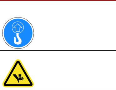
Lift the machine upright.
Moving parts present.
Moving parts can crush and cut.
Keep hands away from moving parts.
18 Safety |
MTS Criterion® Series 40 Product Manual |
Hazard Labels
LABEL |
DESCRIPTION |
|
|
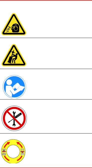
Flying objects.
Danger of eye injury.
Wear safety glasses.
Tip over hazard.
Use outriggers when machine is standalone.
Do not start, operate, or service machine until you read and understand the operator’s manual.
Failure to do so could result in serious injury.
There are no customer-serviceable parts on the MTS Criterion electromechanical frames.
To turn the pulley, manually move the crosshead upward and downward.
Pulleys can be turned by hand when power is disabled.
WEEE The Waste Electrical and Electronic Equipment (WEEE) symbol (  ) means that the controller and its electronic parts must not be disposed of as unsorted municipal waste. Proper disposal is required by approved electronic waste collection agencies. Customers in the EC region who desire to return an end-of- life controller and its electronic parts are encouraged to contact your local MTS Systems Sales/Service Offices for instructions.
MTS Criterion® Series 40 Product Manual |
Safety 19 |
About This Manual
Introduction
About This Manual
Purpose
The purpose of this manual is to help you understand your testing system, its capabilities, and operating requirements. This manual provides information for all MTS Criterion Series 40 Material Test system, from the lowest force model (1 kN), to the highest (600 kN). Read each section carefully and refer to the manual whenever you need assistance.
Inappropriate Use
Contents
Before you attempt to use the MTS Criterion Series 40 Material Test System, read and understand this manual. Improper installation or operation of this product can result in hazardous conditions that can cause severe personal injury or death, and damage your equipment and specimen.
Description 22
Load Frame Components 24
Specifications 35
MTS Criterion® Series 40 Product Manual |
Introduction 21 |

Description
Description
Every MTS Criterion Series 40 Material Test System is comprised of a load frame, electronic frame controller, and testing software.
The load frame has a rectangular shape and includes a base unit and one or two vertical columns. The two-column models have a fixed upper transverse beam. The moving crosshead is driven by precision ball screws on the load frame. The crosshead is coupled to the ball screw(s) with high-strength, precision ball nuts and rides on the ball bearings. This configuration is very efficient in minimizing friction and wear. The ball screws are preloaded. This feature removes the backlash so that position can be measured with increased accuracy over nonpreloaded ball screws.
The load frame drive is located in the frame base. The drive motor is connected to the lower end of the ball screws by a series of belts and drive pulleys. On the two-column machines, motor rotation causes synchronous rotation of the ball screws, which causes the crosshead to move up or down. On the single-column machines, motor rotation causes the rotation of the single ball screw, which causes the crosshead to move up or down.
Frame Controller
The frame controller is responsible for the following:
•Provides main data and signal processing power.
•Detects the activation of limit switches.
•Provides the interface between the software (computer) and the frame.
•Provides digital servocontrol for speed and position accuracy.
•Automatically identifies accessories, including load cells and extensometers, with the self-identify feature.
•Communicates with the handset.
•Provides programmable data acquisition rate (up to 1000 Hz maximum).
•Commands the motor.
Software
MTS testing software has various method templates available. The method templates in the General Testing Package provide a starting point in configuring test methods that conform to your testing needs. The General Testing Package is separated into four specific testing categories:
•MTS Tensile
•MTS Compression
•MTS Flex
•MTS Peel-Tear
22 Introduction |
MTS Criterion® Series 40 Product Manual |
Software
Many additional features can be purchased to meet your company’s specific needs. Some of these features might already be part of the system you ordered, or they can be added to your system as your requirements change. Refer to the testing software manual for additional information.
MTS Criterion® Series 40 Product Manual |
Introduction 23 |
Load Frame Components
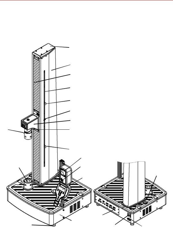
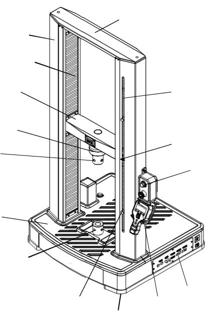
Load Frame Components
The following figures show the various components for the single-column and two-column load frames. To familiarize yourself with the various components of
your frame, refer to the figure that shows your model number.
For dimensions, see the specification tables in the “Specifications” on page 35.
Pin
Adapter
Base Adapter
Mat
Leveling Foot
Top Beam
Column Cover
Ball Screw Cover
Limit Rod
Upper Limit Stop
Limit Switch Actuator
Crosshead
Load Cell (inside)
Lower Limit Stop
System-Enabled Light
Emergency Stop
Manual Unload
Handset
Controller |
|
Base |
|
Power Switch |
Power Cord |
Model C41.103 - Rated Force Capacity 1 kN
24 Introduction |
MTS Criterion® Series 40 Product Manual |
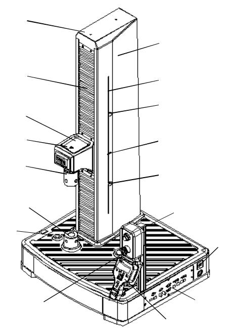
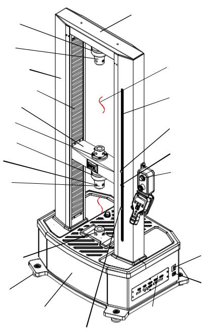
Top Beam
Ball Screw Cover
Crosshead
Load Cell
(inside)
Adapter
Pin 
Base Adapter
Manual Unload
Mat 
Base 
Emergency Stop
Leveling Foot 
Load Frame Components
Column Cover
Limit Rod
Upper Limit Stop
Limit Switch Actuator
Lower Limit Stop
System-Enabled Light
Power Switch
 Power Cord
Controller
Handset
Model C42.503 - Rated Force Capacity 5 kN
MTS Criterion® Series 40 Product Manual |
Introduction 25 |
Load Frame Components
Column Cover 
Ball Screw Cover
Crosshead 
Load Cell 
Pin 
Adapter 
Manual Unload 
Mat 
Base Adapter 
Base 
Lower Limit Stop
 Top Beam
 Limit Rod
 Upper Limit Stop
 Limit Switch Actuator
 System-Enabled Light

 Emergency Stop
 Power Switch
 Power Cord
Controller
Handset
Leveling Foot
Model C43.104 - Rated Force Capacity 10 kN
26 Introduction |
MTS Criterion® Series 40 Product Manual |

Column Cover
Ball Screw Cover
Crosshead
Load Cell
Pin 
Adapter

Load Frame Components
 Top Beam
 Limit Rod
 Upper Limit Stop
 Limit Switch Actuator
Lower Limit Stop
 System-Enabled Light
Emergency Stop
Manual Unload
 Handset
Mat
Power Switch
Base Adapter |
Power Cord |
Base
Controller
Leveling Foot 
Model C43.304 and C43.504 - Rated Force Capacity 30 kN, 50 kN
MTS Criterion® Series 40 Product Manual |
Introduction 27 |
Load Frame Components
Load Cell 
Adapter 
Column Cover 
Ball Screw Cover 
Crosshead 
Adapter 
Load Cell 
Pin 
Adapter 
Lower Test Space
Manual Unload 
Mat 
Base Adapter 
Leveling Foot
Base
Lower Limit Stop
Top Beam
 Upper Test Space
 Limit Rod
 Upper Limit Stop
 Limit Switch Actuator
 System-Enabled Light
 Emergency Stop
 Handset
 Power Switch
 Power Cord
Controller
Model C44.104 and C44.304 - Rated Force Capacity 10 kN, 30 kN
28 Introduction |
MTS Criterion® Series 40 Product Manual |
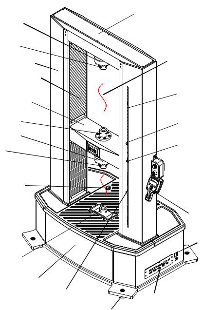
Load Cell 
Adapter 
Column Cover 
Ball Screw Cover
Crosshead 
Adapter
Load Cell 
Pin 
Adapter 

Manual Unload 
Lower Test Space 

Mat 
Base Adapter 
Base 
Lower Limit Stop
Leveling Foot
Load Frame Components
Top Beam
 Upper Test Space
 Limit Rod
 Upper Limit Stop
 Limit Switch Actuator

 System-Enabled Light
 Emergency Stop
 Handset
 Power Switch
 Power Cord
Controller
Model C45.504 and C45.105 - Rated Force Capacity 50 kN, 100 kN
MTS Criterion® Series 40 Product Manual |
Introduction 29 |
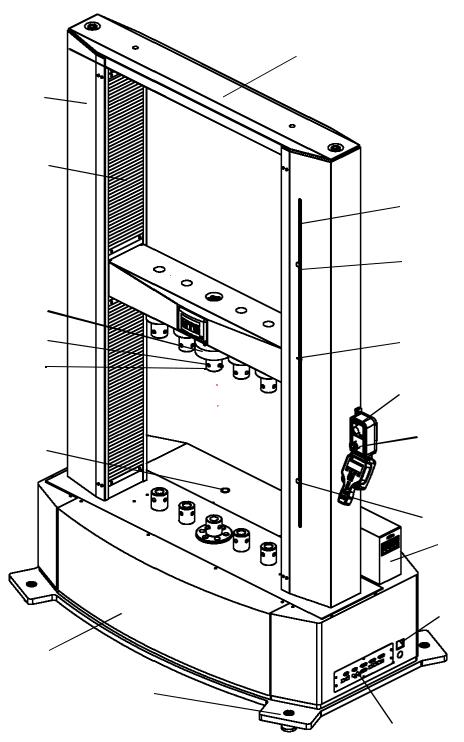
Load Frame Components
Column Cover
Ball Screw Cover 
Crosshead 
Load Cell
Pin
Adapter
Lower Test Space 

Manual Unload
Base Adapter 

Base
Leveling Foot
Top Beam
 Limit Rod
 Upper Limit Stop
 Limit Switch Actuator
 System-Enabled Light
 Emergency Stop

 Handset
 Lower Limit Stop
NI Signal
Acquisition Box
 Power Switch
 Power Cord
 Controller
Model C45.504W - Rated Force Capacity 50 kN
30 Introduction |
MTS Criterion® Series 40 Product Manual |
Loading...