


 Loading...
Series 244 Actuators Product Information
Models 244.11, 244.12, 244.20, 244.21, 244.22, 244.23,
244.31, 244.41, 244.51
011-551-304 G |
be certain. |
© 2013 MTS Systems Corporation. All rights reserved.
Original Instructions (English): 011-551-304 G
Trademark Information
MTS, be certain., Bionix, ElastomerExpress, FlatTrac, FlexTest, Just In Case, LevelPlus, MTS Criterion, MTS EM Extend, MTS Insight, MTS Landmark, RPC, ServoSensor, SWIFT, Temposonics, TestWare, TestWorks are registered trademarks of MTS Systems Corporation within the United States. Acumen, Advantage, Aero ST, Aero-90, AeroPro, Criterion, CRPC, Echo, Flat-Trac, Landmark, MAST, MicroProfiler, MPT, MTS Acumen, MTS Echo, MTS Fundamentals, MTS TestSuite, ReNew, SilentFlo, TempoGuard, TestLine, and Tytron are trademarks of MTS Systems Corporation within the United States. These trademarks may be registered in other countries. All other trademarks are property of their respective owners.
Proprietary Software
Software use and license is governed by the MTS End User License Agreement which defines all rights retained by MTS and granted to the End User. All Software is proprietary, confidential, and owned by MTS Systems Corporation and cannot be copied, reproduced, disassembled, decompiled, reverse engineered, or distributed without express written consent of MTS.
Software Verification and Validation
MTS software is developed using established quality practices in accordance with the requirements detailed in the ISO 9001 standards. Because MTS-authored software is delivered in binary format, it is not user accessible. This software will not change over time. Many releases are written to be backwards compatible, creating another form of verification. The status and validity of the MTS operating software is also checked during system verification and routine calibration of MTS hardware. These controlled calibration processes compare the final test results after statistical analysis against the predicted response of the calibration standards. With these established methods, MTS assures its customers that MTS products meet exacting quality standards when initially installed and will continue to perform as intended over time.
Manual Part Number—Publication Date—Release
011-551-304 G—October 2013
011-551-304 F—September 2008
011-551-304 E—July 2008
011-551-304 D—June 2002
011-551-304 C—May 2000
011-551-304 B—November 1998
011-551-304 A—September 1996
011-551-303 G—June 1994
011-551-303 F—July 1993
011-551-303 E—November 1991
011-551-303 D—June 1990
011-551-303 C—February 1989
011-551-303 B—February 1988
011-551-303 A—June 1987
011-551-302 A—September 1984
011-551-301 A—August 1983
011-551-300 A—December 1982
Contents |
|
Technical Support |
5 |
How to Get Technical Support................................................................................................................. |
5 |
Before You Contact MTS......................................................................................................................... |
5 |
If You Contact MTS by Phone................................................................................................................. |
7 |
Problem Submittal Form in MTS Manuals.............................................................................................. |
8 |
Preface |
9 |
Before You Begin..................................................................................................................................... |
9 |
Documentation Conventions.................................................................................................................... |
9 |
Introduction |
13 |
About the 244 Series Actuator............................................................................................................... |
14 |
What You Need to Know....................................................................................................................... |
14 |
Component Identification....................................................................................................................... |
15 |
Functional Description........................................................................................................................... |
17 |
About Actuator Mounting.......................................................................................................... |
18 |
Actuator Operation..................................................................................................................... |
19 |
LVDT Operation......................................................................................................................... |
19 |
Specifications......................................................................................................................................... |
20 |
Force Ratings.............................................................................................................................. |
20 |
Environmental and Hydraulic Fluid Recommendations........................................................................ |
21 |
Dimensions............................................................................................................................................. |
23 |
LVDT Housing Specifications............................................................................................................... |
26 |
Pedestal Base Specifications.................................................................................................................. |
29 |
Safety |
31 |
General Safety Practices: Hydraulic Power Units and Hydraulic Service Manifolds............................ |
32 |
Safety Practices Before Operating the System....................................................................................... |
33 |
Safety Practices While Operating the System ....................................................................................... |
37 |
Hazard Placard Placement...................................................................................................................... |
38 |
Labels And Icons........................................................................................................................ |
39 |
Warning Label................................................................................................................ |
39 |
Warning Label................................................................................................................ |
39 |
Caution Label................................................................................................................. |
40 |
Attached Mass Warning Label....................................................................................... |
40 |
Hydraulic Actuator ID Tag............................................................................................. |
41 |
Hydraulic Actuator ID Tag............................................................................................. |
41 |
Pressure Icon Label........................................................................................................ |
42 |
Pressure Rating Label..................................................................................................... |
42 |
Lift Hole Thread Size..................................................................................................... |
43 |
Series 244 Actuators Product Information 3
Installation |
45 |
About Installation................................................................................................................................... |
46 |
Load Units.............................................................................................................................................. |
46 |
Installing a Fixture to the Actuator......................................................................................................... |
47 |
Mounting Bolt Specifications..................................................................................................... |
48 |
Spiral Washers........................................................................................................................................ |
50 |
Installing Fixtures with Spiral Washers.................................................................................................. |
51 |
Multiple Fixtures With Different Ratings.................................................................................. |
51 |
Removing Fixtures with Spiral Washers................................................................................................ |
53 |
Multiple Fixtures With Different Ratings.................................................................................. |
54 |
LVDT Cable Connection........................................................................................................................ |
54 |
Hydraulic Connections........................................................................................................................... |
55 |
Operation |
57 |
About Operation..................................................................................................................................... |
58 |
Actuator ID............................................................................................................................................. |
58 |
Operating Considerations....................................................................................................................... |
58 |
Sideload Forces.......................................................................................................................... |
59 |
Sideload Calculation Procedure............................................................................................................. |
59 |
Sample Calculation................................................................................................................................. |
62 |
Maintenance |
65 |
Maintenance Recommendations............................................................................................................. |
66 |
4 Series 244 Actuators Product Information

Technical Support
How to Get Technical Support
Start with your manuals
The manuals supplied by MTS provide most of the information you need to use and maintain your equipment. If your equipment includes software, look for online help and README files that contain additional product information.
Technical support methods
MTS provides a full range of support services after your system is installed. If you have any questions about a system or product, contact Technical Support in one of the following ways.
Web site |
www.mts.com > Contact Us (upper-right corner) > In the Subject field, choose |
|
To escalate a problem; Problem Submittal Form |
Worldwide: tech.support@mts.com |
|
|
Europe: techsupport.europe@mts.com |
Telephone |
Worldwide: 1 800 328 2255 - toll free in U.S.; +1 952 937 4000 - outside U.S. |
|
Europe: +800 81002 222, International toll free in Europe |
Outside the U.S.
For technical support outside the United States, contact your local sales and service office. For a list of worldwide sales and service locations and contact information, use the Global MTS link at the MTS web site:
www.mts.com > Global Presence > Choose a Region
Before You Contact MTS
MTS can help you more efficiently if you have the following information available when you contact us for support.
Know your site number and system number
The site number contains your company number and identifies your equipment type (such as material testing or simulation). The number is typically written on a label on your equipment before the system leaves MTS. If you do not know your MTS site number, contact your sales engineer.
Example site number: 571167
Series 244 Actuators Product Information 5
When you have more than one MTS system, the system job number identifies your system. You can find your job number in your order paperwork.
Example system number: US1.42460
Know information from prior technical assistance
If you have contacted MTS about this problem before, we can recall your file based on the:
•MTS notification number
•Name of the person who helped you
Identify the problem
Describe the problem and know the answers to the following questions:
•How long and how often has the problem occurred?
•Can you reproduce the problem?
•Were any hardware or software changes made to the system before the problem started?
•What are the equipment model numbers?
•What is the controller model (if applicable)?
•What is the system configuration?
Know relevant computer information
For a computer problem, have the following information available:
•Manufacturer’s name and model number
•Operating software type and service patch information
•Amount of system memory
•Amount of free space on the hard drive where the application resides
•Current status of hard-drive fragmentation
•Connection status to a corporate network
Know relevant software information
For software application problems, have the following information available:
•The software application’s name, version number, build number, and (if available) software patch number. This information can typically be found in the About selection in the Help menu.
•The names of other applications on your computer, such as:
•Anti-virus software
•Screen savers
•Keyboard enhancers
•Print spoolers
•Messaging applications
6 Series 244 Actuators Product Information

If You Contact MTS by Phone
A Call Center agent registers your call before connecting you with a technical support specialist. The agent asks you for your:
•Site number
•Name
•Company name
•Company address
•Phone number where you can be reached
If your issue has a notification number, please provide that number. A new issue will be assigned a unique notification number.
Identify system type
To enable the Call Center agent to connect you with the most qualified technical support specialist available, identify your system as one of the following types:
•Electrodynamic material test system
•Electromechanical material test system
•Hydromechanical material test system
•Vehicle test system
•Vehicle component test system
•Aero test system
Be prepared to troubleshoot
Prepare to perform troubleshooting while on the phone:
•Call from a telephone close to the system so that you can implement suggestions made over the phone.
•Have the original operating and application software media available.
•If you are not familiar with all aspects of the equipment operation, have an experienced user nearby to assist you.
Write down relevant information
In case Technical Support must call you:
•Verify the notification number.
•Record the name of the person who helped you.
•Write down any specific instructions.
Series 244 Actuators Product Information 7

After you call
MTS logs and tracks all calls to ensure that you receive assistance for your problem or request. If you have questions about the status of your problem or have additional information to report, please contact Technical Support again and provide your original notification number.
Problem Submittal Form in MTS Manuals
Use the Problem Submittal Form to communicate problems with your software, hardware, manuals, or service that are not resolved to your satisfaction through the technical support process. The form includes check boxes that allow you to indicate the urgency of your problem and your expectation of an acceptable response time. We guarantee a timely response—your feedback is important to us.
You can access the Problem Submittal Form at www.mts.com > Contact Us (upper-right corner) > In the
Subject field, choose To escalate a problem; Problem Submittal Form
8 Series 244 Actuators Product Information

Preface
Before You Begin
Safety first!
Before you use your MTS product or system, read and understand the safety information provided with your system. Improper installation, operation, or maintenance can result in hazardous conditions that can cause severe personal injury or death, or damage to your equipment and specimen. Again, read and understand the safety information provided with your system before you continue. It is very important that you remain aware of hazards that apply to your system.
Other MTS manuals
In addition to this manual, you may receive additional manuals in paper or electronic form.
You may also receive an MTS System Documentation CD. It contains an electronic copy of the manuals that pertain to your test system.
Controller and application software manuals are typically included on the software CD distribution disc(s).
Documentation Conventions
The following paragraphs describe some of the conventions that are used in your MTS manuals.
Hazard conventions
Hazard notices may be embedded in this manual. These notices contain safety information that is specific to the activity to be performed. Hazard notices immediately precede the step or procedure that may lead to an associated hazard. Read all hazard notices carefully and follow all directions and recommendations. Three different levels of hazard notices may appear in your manuals. Following are examples of all three levels. (for general safety information, see the safety information provided with your system.)
Danger:
Danger notices indicate the presence of a hazard with a high level of risk which, if ignored, will result in death, severe personal injury, or substantial property damage.
Series 244 Actuators Product Information 9
Warning:
Warning notices indicate the presence of a hazard with a medium level of risk which, if ignored, can result in death, severe personal injury, or substantial property damage.
Caution:
Caution notices indicate the presence of a hazard with a low level of risk which, if ignored, could cause moderate or minor personal injury or equipment damage, or could endanger test integrity.
Other special text conventions
Important:
Important notices provide information about your system that is essential to its proper function. While not safety-related, if the important information is ignored, test results may not be reliable, or your system may not operate properly.
Note:
Notes provide additional information about operating your system or highlight easily overlooked information.
Recommended:
Recommended notes provide a suggested way to accomplish a task based on what MTS has found to be most effective.
Tip:
Tips provide helpful information or a hint about how to most efficiently accomplish a task.
Access:
Access provides the route you should follow to a referenced item in the software.
Example:
Examples show specific scenarios relating to your product and appear with a shaded background.
Special terms
The first occurrence of special terms is shown in italics.
Illustrations
Illustrations appear in this manual to clarify text. They are examples only and do not necessarily represent your actual system configuration, test application, or software.
Electronic manual conventions
This manual is available as an electronic document in the Portable Document File (PDF) format. It can be viewed on any computer that has Adobe Acrobat Reader installed.
10 Series 244 Actuators Product Information
Hypertext links
The electronic document has many hypertext links displayed in a blue font. All blue words in the body text, along with all contents entries and index page numbers, are hypertext links. When you click a hypertext link, the application jumps to the corresponding topic.
Series 244 Actuators Product Information 11

Introduction
Topics: |
|
|
• About the 244 Series Actuator............................................................................................................... |
14 |
|
• What You Need to Know........................................................................................................................ |
14 |
|
• |
Component Identification....................................................................................................................... |
15 |
• |
Functional Description........................................................................................................................... |
17 |
• |
Specifications......................................................................................................................................... |
20 |
• Environmental and Hydraulic Fluid Recommendations......................................................................... |
21 |
|
• |
Dimensions............................................................................................................................................ |
23 |
• |
LVDT Housing Specifications................................................................................................................ |
26 |
• |
Pedestal Base Specifications................................................................................................................ |
29 |
Series 244 Actuators Product Information 13
Introduction
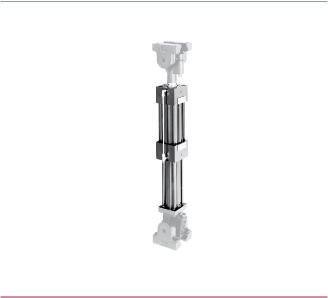
About the 244 Series Actuator
The Series 244 Actuator is a hydraulically powered device that provides displacement of (or forces into) a specimen or structure for testing.
What You Need to Know
MTS Systems Corporation assumes that you know how to use your controller. See the appropriate manual for information about performing any controller-related step in this manual’s procedure. You are expected to know how to perform the following procedures:
•Turn hydraulic pressure on and off.
•Select a control mode.
•Manually adjust the actuator position.
•Install a specimen.
•Define a simple test.
•Run a test.
14 Series 244 Actuators Product Information

Introduction
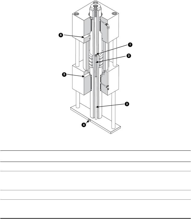
Component Identification
Series 244 Actuators Product Information 15

Introduction |
|
|
|
|
Series 244 Hydraulic Actuator Major Components |
Item |
Component |
Description |
1 |
Piston rod end |
The piston rod has a hardened steel insert that provides an |
|
|
internal thread for mounting load cells, swivels, and interface |
|
|
fixtures. The Model 244.51 Actuator has no insert; internal |
|
|
threads are machined directly into the piston rod end. |
2 |
Bearing |
The high-capacity nonmetallic bearings bond directly to the |
|
|
end caps. The non-metallic bearings are standard because of |
|
|
their high side-load tolerance and resistance to failure from |
|
|
galling and seizure. |
3 |
Cushion |
The cushions protect the actuator from the effects of |
|
|
high-speed and high-mass forces. They prevent the actuator |
|
|
from contacting the end caps. The Model 244.41 and 244.51 |
|
|
Actuators do not have hydraulic cushions. |
4 |
Extension Port/ |
High-pressure hydraulic fluid enters the cylinder through one |
|
Retraction Port |
of these control ports. As pressure is applied to one port, the |
|
|
other port is opened to a return line causing the actuator to |
|
|
extend or to retract. Fluid flow through these ports is controlled |
|
|
by the servovalve. |
5 |
Piston seal |
A reinforced Teflon seal (if equipped) on the piston provides |
|
|
a positive seal and reduces friction. Grooves on the piston |
|
|
lubricate the piston surface during short-stroke, side-loaded |
|
|
tests. For high-speed cyclic testing applications, the piston |
|
|
seal can be omitted. The close tolerance fit provides an |
|
|
effective viscous seal. |
6 |
Piston rod |
The Series 244 Actuator is equipped with a double-ended |
|
|
piston rod. The double-ended piston has equal areas on both |
|
|
sides for balanced performance. It is machined from a single |
|
|
piece of heat-treated alloy steel and is hard-chrome plated. |
|
|
The piston rod is hollow to allow for installation and accurate |
|
|
alignment of a displacement transducer. |
7 |
Drainback Port |
The drainback port allows fluid that manages to leak past the |
|
|
seals to be routed out of the actuator which prevents pressure |
|
|
pockets from interfering with actuator performance. |
8High/Low Pressure The piston rod seals consist of a high-pressure seal and a
Seals |
low-pressure/wiper seal in both the front end cap and the rear |
|
end cap. |
|
Model 244.1x and 244.2x Actuators [with force ratings under |
|
100 kN (22 kip)], that are used in load frame/unit applications |
|
do not contain high-pressure piston rod seals. |
|
The high-pressure seal is designed for long life, low friction, |
|
and exceptional performance in high-frequency, |
|
low-displacement applications. A small amount of hydraulic |
|
fluid is allowed to flow past the high-pressure seal for |
|
continuous bearing lubrication. Drainback ports return the |
16 Series 244 Actuators Product Information

Introduction
Item |
Component |
Description |
hydraulic fluid passed by the high-pressure seal back to the system hydraulic power supply.
The inner part of the low-pressure/wiper seal provides a hydraulic seal, while the outer part of the seal functions as a scraper ring to minimize external contamination of the seals and bearings. When a high-pressure seal is present, the inner part of the low-pressure seal wipes hydraulic fluid that gets by the high-pressure seal and guides the fluid into the drainback port.
Functional Description
The Series 244 Actuator is a double-acting, double-ended, heavy-duty actuator that operates under precision servovalve control in MTS closed-loop servohydraulic systems. The actuator is a hydraulically powered piston that can extend or retract (double-acting). The actuator provides displacement of (or force into) a specimen or structure for testing. It can also provide equal power in tension and compression (double-ended). The actuator includes an LVDT which measures the displacement of the actuator.
The Series 244 Actuator is linear and is associated with axial control channels. A linear actuator consists of a cylinder that contains a piston.
The Series 244 Actuator is designed to accept a wide variety of options and accessories including force and displacement transducers, pedestal bases, swivel rod ends, and swivel bases. When equipped with the appropriate options and accessories, the actuator can be configured for precision testing of materials, structures, and components.
Series 244 Actuators Product Information 17
Introduction
Functional Diagram
Item Description
1LVDT Core Mount
2LVDT Core Extension
3LVDT Coil
4LVDT Connector
5Extension Port
6Retraction Port
About Actuator Mounting
The actuator can be mounted to a wide variety of fixtures and assemblies:
•Component test systems usually have one end of the actuator connected to a custom test frame base and the other end connected to the test specimen. Either end of the actuator may use mounting fixtures (such as swivels) to attach it to the specimen or base.
18 Series 244 Actuators Product Information
Introduction
•Material test systems usually mount the actuator in a load unit assembly. The actuator can be mounted below the base plate or above the crosshead. The end of the actuator uses fixtures (such as grips) to attach the test specimen to it.
Actuator Operation
Actuator piston rod movement is accomplished by supplying highpressure hydraulic fluid to one side of the actuator piston and opening the other side to a return line. High-pressure hydraulic fluid is ported into the cylinder through the retraction port or the extension port. The differential pressure across the piston forces the piston rod to move. The amount of hydraulic fluid and the speed and direction of piston rod movement is controlled by a servovalve.
If the piston rod contacts some external reaction point, then a force is applied to that point equal to the effective piston area times the actuating pressure. The main criteria for selecting an actuator are the force and stroke (displacement) required for the job.
LVDT Operation
The internally mounted LVDT (linear variable differential transformer) provides an indication of the actuator piston rod displacement.
Series 244 Actuators Product Information 19

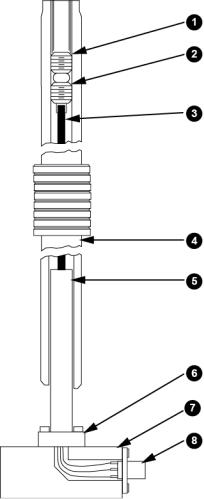
Introduction
LVDT Components
Item Description
1Locking Setscrew
2Core Mount Setscrew
3LVDT Core Extension
4Hollow Piston Rod
5LVDT Coil
6Locking Collar
7Pedestal Base
8LVDT Connector
The LVDT is an electromechanical device that provides an output voltage which is proportional to the displacement of a moveable core extension. The core extension is mounted inside the hollow piston rod and moves as the piston rod moves. The LVDT coil is secured to the pedestal base by a locking collar. The core extension is positioned in the LVDT coil to provide a zero reference point, and is locked in place with a locking setscrew.
As the piston rod moves during operation, the output voltage from the LVDT indicates how far the piston rod has moved from the zero reference point.
Specifications
Several types of specifications are listed on the following pages. All specifications are subject to change without notice. Contact MTS for verification of specifications critical to your needs.
Force Ratings
The following table lists the force rating of each actuator model. The rod diameter and effective piston area specifications are used in the “Operating Considerations.”
|
Actuator Specifications (Metric) |
|
|
Model |
Force Rating1 |
Rod Diameter |
Effective Piston Area |
Number |
Kn |
mm |
cm2 |
244.11 |
15 |
44.5 |
7.50 |
244.12 |
25 |
44.5 |
13.50 |
1 Nominal force achieved with 21 MPa (3000 psi) hydraulic pressure.
20 Series 244 Actuators Product Information
|
|
|
Introduction |
Model |
Force Rating1 |
Rod Diameter |
Effective Piston Area |
Number |
Kn |
mm |
cm2 |
244.20 |
68 |
69.9 |
33.68 |
244.21 |
50 |
69.9 |
25.16 |
244.22 |
100 |
69.9 |
48.84 |
244.23 |
160 |
69.9 |
82.13 |
244.31 |
250 |
95.3 |
126.65 |
244.41 |
500 |
133.4 |
248.28 |
244.51 |
1000 |
152.4 |
487.70 |
|
Actuator Specifications (U.S. Customary) |
|
|
Model |
Force Rating2 |
Rod Diameter |
Effective Piston Area |
Number |
Kip |
in |
in2 |
244.11 |
3.3 |
1.75 |
1.17 |
244.12 |
5.5 |
1.75 |
2.10 |
244.20 |
15.0 |
2.75 |
5.22 |
244.21 |
11.0 |
2.75 |
3.90 |
244.22 |
22.0 |
2.75 |
7.57 |
244.23 |
35.0 |
2.75 |
12.73 |
244.31 |
55.0 |
3.75 |
19.63 |
244.41 |
110.0 |
5.25 |
38.48 |
244.51 |
220.0 |
6.00 |
75.60 |
Environmental and Hydraulic Fluid
Recommendations
Environmental |
For use in a controlled environment. |
1 Nominal force achieved with 21 MPa (3000 psi) hydraulic pressure. 2 Nominal force achieved with 21 MPa (3000 psi) hydraulic pressure.
Series 244 Actuators Product Information 21
Loading...