


 Loading...
m
be certain.
Series 215 Rotary Actuator
Product Information
011-199-001 C

Copyright information Trademark information
Publication information
© 1996, 2000, 2008 MTS Systems Corporation. All rights reserved.
MTS is a registered trademark of MTS Systems Corporation within the United States. This trademark may be protected in other countries.
DTE is a registered trademark of Mobil Corporation.
Tellus is a registered trademark of Shell Oil Corporation.
Molykote is a registered trademark of Dow Chemical Corporation.
Manual Part Number |
Publication Date |
|
|
011-199-001 A |
April 1996 |
|
|
011-199-001 B |
June 2000 |
|
|
011-199-001 C |
March 2008 |
|
|
2 |
Manual Template 4.3 |

Contents
Technical Support 5
How to Get Technical Support 5 Before You Contact MTS 5
If You Contact MTS by Phone 6
Problem Submittal Form in MTS Manuals 7
Preface 9
Before You Begin 9
Conventions 10
Documentation Conventions 10
Introduction 13
Functional Description 13
Optional Equipment 13
Closed-Loop Rotary Actuator Systems 15
Actuator Specifications 16
Options Specifications 19
Reaction Brackets 22
Reaction Bases 23
Diaphragm Flexures 24
Flange Adapters 25
Safety Information 27
Hazard Placard Placement 27
Series 215 Rotary Actuator Product Manual |
3 |

Installation 31
Actuator Installation 32
Reaction Bracket and Torque Cell Installation 32 Diaphragm Flexure Installation 34
Aligning Force Train Components 34 Component Alignment on an MTS Base Plate 35 Component Centerline Alignment 35
Adjusting Actuator and Torque Cell Centerline Height 35 Adjusting Actuator and Torque Cell Concentricity 36 Adjusting Actuator and Torque Cell Centerline Angularity 37
Operation 39
Thrust and Side Load Characteristics 39
Definition of Useful Mathematical Terms 40
Test Setup Using No Flexures 42
Test Setup Using Standard Flexures 46
Test Setup Using Diaphragm Flexures 50
Summary of Side Load Calculations 54
Rotational Inertial 57
Determining Maximum Rotational Inertia (JT) 57
Rotational Inertia Control Options 60
Maintenance 61
Routine Maintenance 61
Actuator Performance Checks 61
Actuator Inspection 64
4 |
Series 215 Rotary Actuator Product Manual |

How to Get Technical Support
Technical Support
How to Get Technical Support
Start with your manuals
Technical support methods
MTS web site
www.mts.com
Telephone
Fax
The manuals supplied by MTS provide most of the information you need to use and maintain your equipment. If your equipment includes MTS software, look for online help and README files that contain additional product information.
If you cannot find answers to your technical questions from these sources, you can use the internet, e-mail, telephone, or fax to contact MTS for assistance.
MTS provides a full range of support services after your system is installed. If you have any questions about a system or product, contact MTS in one of the following ways.
The MTS web site gives you access to our technical support staff by means of a Technical Support link:
www.mts.com > Contact Us > Service & Technical Support
techsupport@mts.com
MTS Call Center 800-328-2255
Weekdays 7:00 A.M. to 5:00 P.M., Central Time
952-937-4515
Please include “Technical Support” in the subject line.
Before You Contact MTS
Know your site number and system number
MTS can help you more efficiently if you have the following information available when you contact us for support.
The site number contains your company number and identifies your equipment type (material testing, simulation, and so forth). The number is usually written on a label on your MTS equipment before the system leaves MTS. If you do not have or do not know your MTS site number, contact your MTS sales engineer.
Example site number: 571167
When you have more than one MTS system, the system job number identifies which system you are calling about. You can find your job number in the papers sent to you when you ordered your system.
Example system number: US1.42460
Series 215 Rotary Actuator Product Manual |
Technical Support |
5 |
If You Contact MTS by Phone
Know information from If you have contacted MTS about this problem before, we can recall your file. prior technical You will need to tell us the:
assistance
•MTS notification number
•Name of the person who helped you
Identify the problem Describe the problem you are experiencing and know the answers to the following questions:
•How long and how often has the problem been occurring?
•Can you reproduce the problem?
•Were any hardware or software changes made to the system before the problem started?
Know relevant computer information
•What are the model numbers of the suspect equipment?
•What model controller are you using (if applicable)?
•What test configuration are you using?
If you are experiencing a computer problem, have the following information available:
•Manufacturer’s name and model number
Know relevant software information
•Operating software type and service patch information
•Amount of system memory
•Amount of free space on the hard drive in which the application resides
•Current status of hard-drive fragmentation
•Connection status to a corporate network
For software application problems, have the following information available:
•The software application’s name, version number, build number, and if available, software patch number. This information is displayed briefly when you launch the application, and can typically be found in the “About” selection in the “Help” menu.
•It is also helpful if the names of other non-MTS applications that are running on your computer, such as anti-virus software, screen savers, keyboard enhancers, print spoolers, and so forth are known and available.
If You Contact MTS by Phone
Your call will be registered by a Call Center agent if you are calling within the United States or Canada. Before connecting you with a technical support specialist, the agent will ask you for your site number, name, company, company address, and the phone number where you can normally be reached.
6 |
Technical Support |
Series 215 Rotary Actuator Product Manual |
Problem Submittal Form in MTS Manuals
Identify system type
Be prepared to troubleshoot
Write down relevant information
After you call
If you are calling about an issue that has already been assigned a notification number, please provide that number. You will be assigned a unique notification number about any new issue.
To assist the Call Center agent with connecting you to the most qualified technical support specialist available, identify your system as one of the following types:
•Electromechanical materials test system
•Hydromechanical materials test system
•Vehicle test system
•Vehicle component test system
•Aero test system
Prepare yourself for troubleshooting while on the phone:
•Call from a telephone when you are close to the system so that you can try implementing suggestions made over the phone.
•Have the original operating and application software media available.
•If you are not familiar with all aspects of the equipment operation, have an experienced user nearby to assist you.
Prepare yourself in case we need to call you back:
•Remember to ask for the notification number.
•Record the name of the person who helped you.
•Write down any specific instructions to be followed, such as data recording or performance monitoring.
MTS logs and tracks all calls to ensure that you receive assistance and that action is taken regarding your problem or request. If you have questions about the status of your problem or have additional information to report, please contact MTS again and provide your original notification number.
Problem Submittal Form in MTS Manuals
Use the Problem Submittal Form to communicate problems you are experiencing with your MTS software, hardware, manuals, or service which have not been resolved to your satisfaction through the technical support process. This form includes check boxes that allow you to indicate the urgency of your problem and your expectation of an acceptable response time. We guarantee a timely response—your feedback is important to us.
The Problem Submittal Form can be accessed:
•In the back of many MTS manuals (postage paid form to be mailed to MTS)
•www.mts.com > Contact Us > Problem Submittal Form (electronic form to be e-mailed to MTS)
Series 215 Rotary Actuator Product Manual |
Technical Support |
7 |
Problem Submittal Form in MTS Manuals
8 |
Technical Support |
Series 215 Rotary Actuator Product Manual |

Before You Begin
Preface
Before You Begin
Safety first!
Other MTS manuals
Before you attempt to use your MTS product or system, read and understand the Safety manual and any other safety information provided with your system. Improper installation, operation, or maintenance of MTS equipment in your test facility can result in hazardous conditions that can cause severe personal injury or death and damage to your equipment and specimen. Again, read and understand the safety information provided with your system before you continue. It is very important that you remain aware of hazards that apply to your system.
In addition to this manual, you may receive additional MTS manuals in paper or electronic form.
If you have purchased a test system, it may include an MTS System Documentation CD. This CD contains an electronic copy of the MTS manuals that pertain to your test system, including hydraulic and mechanical component manuals, assembly drawings and parts lists, and operation and preventive maintenance manuals. Controller and application software manuals are typically included on the software CD distribution disc(s).
Series 215 Rotary Actuator Product Manual |
Preface |
9 |

Conventions
Conventions
Documentation Conventions
Hazard conventions
Notes
Special terms
Illustrations
Electronic manual conventions
The following paragraphs describe some of the conventions that are used in your MTS manuals.
As necessary, hazard notices may be embedded in this manual. These notices contain safety information that is specific to the task to be performed. Hazard notices immediately precede the step or procedure that may lead to an associated hazard. Read all hazard notices carefully and follow the directions that are given. Three different levels of hazard notices may appear in your manuals. Following are examples of all three levels.
Note For general safety information, see the safety information provided with your system.

 DANGER
Danger notices indicate the presence of a hazard with a high level of risk which, if ignored, will result in death, severe personal injury, or substantial property damage.

 WARNING
Warning notices indicate the presence of a hazard with a medium level of risk which, if ignored, can result in death, severe personal injury, or substantial property damage.

 CAUTION
Caution notices indicate the presence of a hazard with a low level of risk which, if ignored, could cause moderate or minor personal injury, equipment damage, or endanger test integrity.
Notes provide additional information about operating your system or highlight easily overlooked items. For example:
Note Resources that are put back on the hardware lists show up at the end of the list.
The first occurrence of special terms is shown in italics.
Illustrations appear in this manual to clarify text. It is important for you to be aware that these illustrations are examples only and do not necessarily represent your actual system configuration, test application, or software.
This manual is available as an electronic document in the Portable Document File (PDF) format. It can be viewed on any computer that has Adobe Acrobat Reader installed.
10 |
Preface |
Series 215 Rotary Actuator Product Manual |
Documentation Conventions
Hypertext links The electronic document has many hypertext links displayed in a blue font. All blue words in the body text, along with all contents entries and index page numbers, are hypertext links. When you click a hypertext link, the application jumps to the corresponding topic.
Series 215 Rotary Actuator Product Manual |
Preface |
11 |
Documentation Conventions
12 |
Preface |
Series 215 Rotary Actuator Product Manual |
Functional Description
Introduction
Functional Description
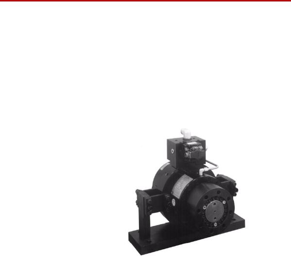
MTS Series 215 Rotary Actuators are heavy-duty, torque-generating actuators that operate under precision servovalve control. When coupled with an appropriate MTS servovalve and transducer, Series 215 Actuators provide the rotational motion and torque required to torsion test materials and components. These actuators receive drive power from a hydraulic power unit via a servovalve which is manifold-mounted to the top of the actuator.
Series 215 Actuators have a maximum static displacement of 100° or ±50°. The maximum dynamic displacement is 90˚ or ±45° with hydraulic cushions in the last 5° of displacement.
Series 215 Rotary Actuator
The preceding figure shows a Series 215 Rotary Actuator with an attached Servovalve/Servovalve manifold, flange adapter, and foot mounting assembly.
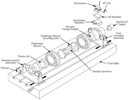
Optional Equipment
A variety of options are available for the Series 215 Rotary Actuators. The following figure and table show a test system containing a rotary actuator and the available optional components.
Series 215 Rotary Actuator Product Manual |
Introduction |
13 |
Optional Equipment
|
Rotary Actuator Test System with Optional Equipment |
|
Optional Equipment for Series 215 Rotary Actuators |
OPTION |
FUNCTION |
|
|
Reaction base plate or A reaction base plate or T-slot table is used with the rotary actuator for two |
|
T-slot table |
purposes; (1) it provides a mounting surface for the actuator and drive train |
|
components; (2) it provides a structure which can react the large forces generated |
|
by the rotary actuator. |
|
|
Flange adapter |
The flange adapter (located behind the diaphragm flexure in the photograph) is |
|
secured to the actuator rotor shaft by a split flange clamp assembly. It provides a |
|
coupling surface between the actuator and specimen adapter plate or diaphragm |
|
flexure. |
|
|
Diaphragm flexures |
Diaphragm flexures should be used at both ends of the specimen if large axial and |
|
angular deflections are generated during testing. If reaction forces exceed stated |
|
actuator operating limits, diaphragm flexures help reduce the thrust and side loads |
|
experienced by the actuator. |
|
|
Reaction bracket |
The reaction bracket attaches securely to the reaction base plate or T-slot table and |
|
provides a mounting surface for the torque cell. Each reaction bracket is designed |
|
to restrain a specific model torque cell. |
|
|
14 |
Introduction |
Series 215 Rotary Actuator Product Manual |
Closed-Loop Rotary Actuator Systems
Optional Equipment for Series 215 Rotary Actuators (Continued)
Torque cell |
A torque cell provides a precise electrical feedback signal that is proportional to |
|
the torque applied to the specimen. For more information on MTS torque cells, |
|
refer to the appropriate MTS product specification. |
|
|
ADT |
An angular displacement transducer (ADT) connected to the rear shaft of the |
|
actuator produces a DC electrical signal that is proportional to the angular position |
|
of the actuator. Rotation of the actuator will generate a feedback signal |
|
(0 V DC to ±10 V DC) from the ADT to the transducer conditioner. Rotation is |
|
continuous with no reactive torque induced. The ADT is a precision differential |
|
capacitor coupled to a solid state oscillator, demodulator, and amplifier to yield |
|
DC input - DC output performance. |
|
|
RVDT |
A rotary variable differential transformer (RVDT) attached to the rear shaft of the |
|
actuator provides an AC feedback signal proportional to the angular position of |
|
the actuator. As the actuator rotates, a feedback signal is sent to the transducer |
|
conditioner. An RVDT converts a mechanical angular displacement into an |
|
electrical output by means of an electrical input carrier. It consists of a rotor |
|
assembly to which the mechanical input is applied, and a stator assembly in which |
|
the windings are contained. |
|
|
Differential pressure |
The differential pressure (∆P) cell is a single-unit, dual port, bonded strain gage |
cell |
pressure sensor. Depending on the specific application, the ∆P cell is used to |
|
stabilize or control actuator force output. The ∆P cell (located beneath the |
|
servovalve) provides a feedback signal to a controller monitoring fluid pressure |
|
within the actuator housing. For more information on MTS ∆P cells, refer to the |
|
appropriate MTS product specification. |
|
|
Closed-Loop Rotary Actuator Systems
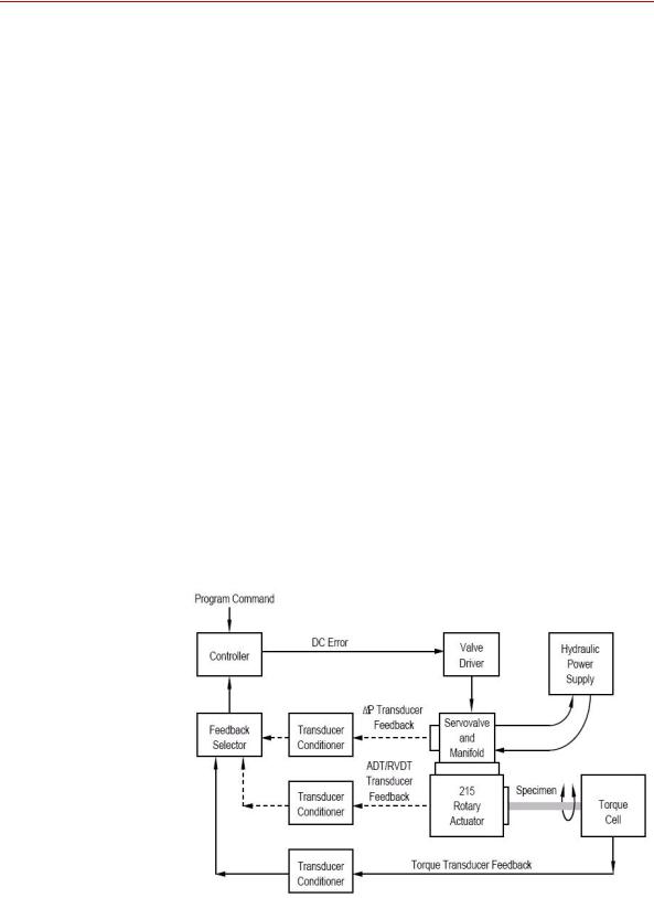
In a closed-loop control system containing a rotary actuator, a command signal sent to the actuator servovalve is compared to a feedback signal received from an actuator transducer. The following figure shows a block diagram of the major components in a typical rotary actuator closed-loop control system.
Block Diagram of a Testing System Using a Rotary Actuator
Series 215 Rotary Actuator Product Manual |
Introduction |
15 |

Actuator Specifications
As the block diagram shows, a program command signal is input to the controller. The command signal is compared to the feedback signal from one of the actuator transducers. If the command signal equals the feedback signal from the transducer conditioner, no DC error is present and the valve driver circuit produces little or no servovalve control signal. If the command signal does not equal the feedback signal, a DC error signal is sent to the valve driver circuit.
The valve driver circuit uses this signal to generate a servovalve control signal. The servovalve control signal causes the servovalve spool to open in a direction and by an amount necessary to direct a regulated flow of hydraulic fluid to the actuator’s pressure or return ports. The actuator moves in response to the flow of hydraulic fluid. The constant feedback of the closed-loop system enables the controller to maintain precise control of actuator torque or movement.
Actuator Specifications
Series 215 Rotary Actuators are available in six models. This section lists specifications for both the Series 215 Actuator and its options.
Series 215 Rotary Actuator Ratings by Model
MODEL |
RATED |
|
DISPLACEMENT |
THRUST LOAD |
SIDE |
|
BENDING |
|
|||
|
TORQUE* |
|
|
|
|
Q (MAXIMUM) |
LOAD† |
|
MOMENT |
|
|
|
|
|
|
|
|
|
|
P (MAXIMUM) |
M (MAXIMUM) |
||
|
|
|
|
|
|
|
|
|
|
|
|
|
lbf·in. |
N·m |
in. |
/rad |
cm /rad |
lbf |
kN |
lbf |
kN |
lbf·in. |
N·m |
|
|
|
3 |
|
3 |
|
|
|
|
|
|
215.32 |
2000 |
226 |
0.80 |
13.1 |
750 |
3.3 |
1500 |
6.67 |
3600 |
405 |
|
|
|
|
|
|
|
|
|
|
|
|
|
215.35 |
5000 |
565 |
1.9 |
|
31.1 |
750 |
3.3 |
3500 |
15.57 |
15,400 |
1732 |
|
|
|
|
|
|
|
|
|
|
|
|
215.41 |
10,000 |
1130 |
3.7 |
|
60.6 |
750 |
3.3 |
3500 |
15.57 |
15,400 |
1732 |
|
|
|
|
|
|
|
|
|
|
|
|
215.42 |
20,000 |
2260 |
7.2 |
|
117.9 |
750 |
3.3 |
3500 |
15.57 |
17,300 |
1946 |
|
|
|
|
|
|
|
|
|
|
|
|
215.45 |
50,000 |
5650 |
19.0 |
311.3 |
1200 |
5.3 |
5700 |
25.36 |
43,000 |
4837 |
|
|
|
|
|
|
|
|
|
|
|
|
|
215.51 |
100,000 |
11,300 |
38.0 |
622.7 |
1200 |
5.3 |
6500 |
28.92 |
50,000 |
5625 |
|
*Actuator is designed for cyclic use at rated torque: rated at maximum differential pressure at 21 MPa (3000 psi).
†P and M are interdependent: if P is at maximum, M must be zero; if P = 75% of maximum, M may be up to 25% of its maximum value.
‡If these values are to be exceeded, additional internal or external cushions are required; contact MTS.
§w = rotational velocity in rad/sec and J or I = rotational inertia in lbm-in.2 or kg-m2 including inertias from rotary actuator, flange, flexure, and 1/2 of test specimen (lbm = pounds mass).
¶ Does not include flange adapter.
16 |
Introduction |
Series 215 Rotary Actuator Product Manual |
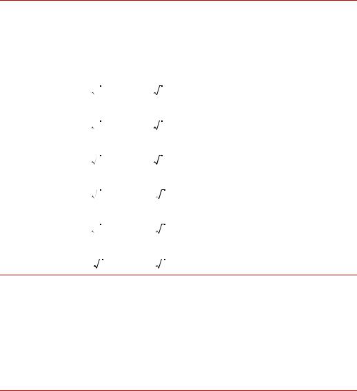
Actuator Specifications
Series 215 Rotary Actuator Ratings by Model
MODEL |
MAX VELOCITY |
|
ROTARY ACTUATOR ROTATIONAL INERTIA¶ |
||
|
CUSHION LIMITATION‡ |
|
|
|
|
|
|
|
|
|
|
|
U.S. |
SI Metric |
lbm-in. |
2 |
kg-m |
|
|
|
|
2 |
|
|
Customary |
rad/sec |
J |
|
I |
|
rad/sec |
|
|
|
|
|
|
|
|
|
|
215.32 |
w= 260-------- |
w= 4.4------ |
11.67 |
|
0.00342 |
|
J |
I |
|
|
|
|
|
|
|
|
|
215.35 |
w= 305-------- |
w= 5.2------ |
18.54 |
|
0.00544 |
|
J |
I |
|
|
|
|
|
|
|
|
|
215.41 |
w= 385-------- |
w= 6.6------ |
20.23 |
|
0.00594 |
|
J |
I |
|
|
|
|
|
|
|
|
|
215.42 |
w= 840-------- |
w= 14.4--------- |
29.04 |
|
0.00852 |
|
J |
I |
|
|
|
|
|
|
|
|
|
215.45 |
w= 970-------- |
w= 16.6--------- |
171 |
|
0.0500 |
|
J |
I |
|
|
|
|
|
|
|
|
|
215.51 |
w= 1525----------- |
w= 26.1--------- |
284 |
|
0.0831 |
|
J |
I |
|
|
|
*Actuator is designed for cyclic use at rated torque: rated at maximum differential pressure at 21 MPa (3000 psi).
†P and M are interdependent: if P is at maximum, M must be zero; if P = 75% of maximum, M may be up to 25% of its maximum value.
‡If these values are to be exceeded, additional internal or external cushions are required, contact MTS.
§w = rotational velocity in rad/sec and J or I = rotational inertia in lbm-in.2 or kg-m2 including inertias from rotary actuator, flange, flexure, and 1/2 of test specimen (lbm = pounds mass).
¶ Does not include flange adapter.
Series 215 Rotary Actuator Product Manual |
Introduction |
17 |
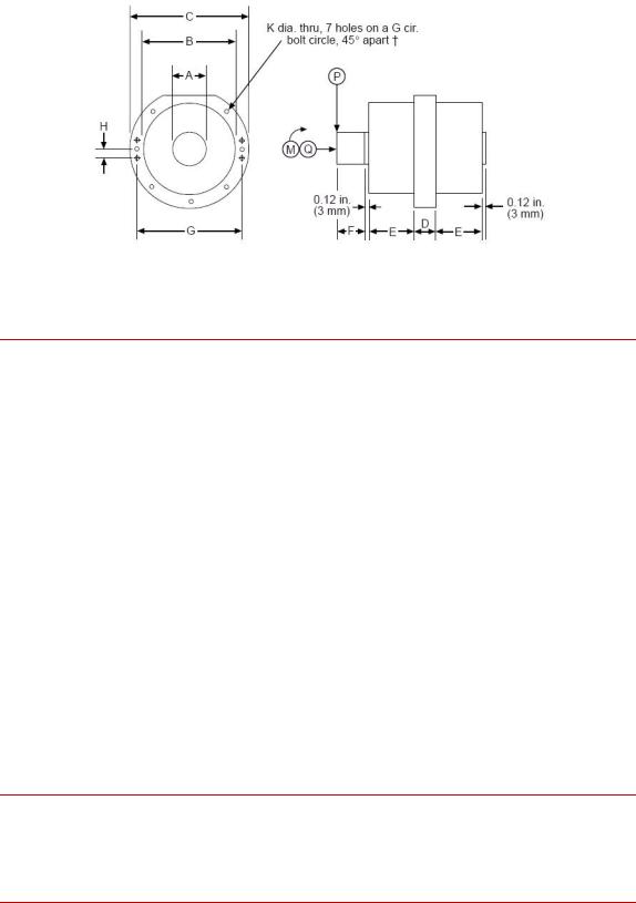
Actuator Specifications
Actuator Dimensional Drawing
Actuator Dimensions and Weights
|
A |
|
B |
|
C |
|
D |
|
E |
|
|
|
|
|
|
|
|
|
|
|
|
MODEL |
IN. |
MM |
IN. |
MM |
IN. |
MM |
IN. |
MM |
IN. |
MM |
|
|
|
|
|
|
|
|
|
|
|
215.32 |
1.50 |
38.1 |
7.875 |
200.0 |
10.00 |
254 |
1.175 |
29.8 |
3.130 |
79.5 |
|
|
|
|
|
|
|
|
|
|
|
215.35 |
2.251 |
57.1 |
7.875 |
200.0 |
10.00 |
254 |
2.275 |
57.8 |
3.130 |
79.5 |
|
|
|
|
|
|
|
|
|
|
|
215.41 |
2.251 |
57.1 |
7.875 |
200.0 |
10.00 |
254 |
2.275 |
57.8 |
3.130 |
79.5 |
|
|
|
|
|
|
|
|
|
|
|
215.42 |
2.251 |
57.1 |
7.875 |
200.0 |
10.00 |
254 |
3.275 |
83.2 |
3.130 |
79.5 |
|
|
|
|
|
|
|
|
|
|
|
215.45 |
3.751 |
95.3 |
9.875 |
250.8 |
12.25 |
311 |
2.775 |
74.5 |
4.137 |
105.1 |
|
|
|
|
|
|
|
|
|
|
|
215.51 |
3.751 |
95.3 |
9.875 |
250.8 |
12.25 |
311 |
5.553 |
141.0 |
4.137 |
105.1 |
|
|
|
|
|
|
|
|
|
|
|
|
F |
|
G |
|
H |
|
K |
|
WEIGHT |
|
|
|
|
|
|
|
|
|
|
|
|
MODEL |
IN. |
MM |
IN. |
MM |
IN. |
MM |
IN. |
MM |
LB |
KG |
|
|
|
|
|
|
|
|
|
|
|
215.32 |
2.50 |
63.5 |
9.000 |
228.6 |
1.000 |
25.4 |
0.406 |
10.3 |
100 |
45 |
|
|
|
|
|
|
|
|
|
|
|
215.35 |
2.50 |
63.5 |
9.000 |
228.6 |
1.000 |
25.4 |
0.406 |
10.3 |
130 |
59 |
|
|
|
|
|
|
|
|
|
|
|
215.41 |
2.50 |
63.5 |
9.000 |
228.6 |
1.000 |
25.4 |
0.406 |
10.3 |
130 |
59 |
|
|
|
|
|
|
|
|
|
|
|
215.42 |
2.99 |
75.9 |
9.000 |
228.6 |
1.000 |
25.4 |
0.406 |
10.3 |
150 |
70 |
|
|
|
|
|
|
|
|
|
|
|
215.45 |
3.49* |
88.6* |
11.000 |
279.4 |
1.000 |
25.4 |
0.656 |
16.7 |
270 |
125 |
|
|
|
|
|
|
|
|
|
|
|
215.51 |
5.12* |
130.0* |
11.000 |
279.4 |
1.000† |
25.4† |
0.656 |
16.7 |
365 |
165 |
*Contains a 3.0 mm (0.12 in.) shoulder that is 0.25 mm (0.01 in.) larger in diameter than Dimension 'A'.
† 215.51 pattern has more bolt holes, not evenly spaced.
Dimensions and weights are subject to change without notice. Contact MTS for dimensions and weights critical to your needs.
18 |
Introduction |
Series 215 Rotary Actuator Product Manual |
Options Specifications
Options Specifications
Specifications for the most common options available for use with the Series 215
Rotary Actuators are described below.
Foot Mounting The foot mounting option is used for easy attachment of the actuator to a reaction base and also provides some flexure capability.
Series 215 Rotary Actuator Product Manual |
Introduction |
19 |

Options Specifications
Foot Mounting Dimensions and Ratings
MODEL |
A |
|
B |
|
C |
|
D |
|
|
|
|
|
|
|
|
|
|
|
IN. |
MM |
IN. |
MM |
IN. |
MM |
IN. |
MM |
|
|
|
|
|
|
|
|
|
215.32 |
6.25 |
158.8 |
0.75 |
19 |
5.00 |
127 |
17.00 |
432 |
|
|
|
|
|
|
|
|
|
215.35 |
6.25 |
158.8 |
0.75 |
19 |
5.00 |
127 |
17.00 |
432 |
|
|
|
|
|
|
|
|
|
215.41 |
6.50 |
166.4 |
1.00 |
25 |
5.00 |
127 |
19.50 |
495 |
|
|
|
|
|
|
|
|
|
215.42 |
6.50 |
166.4 |
1.00 |
25 |
5.00 |
127 |
19.50 |
495 |
|
|
|
|
|
|
|
|
|
215.45 |
7.75 |
196.8 |
1.50 |
38 |
6.00 |
152 |
22.00 |
559 |
|
|
|
|
|
|
|
|
|
215.51 |
7.75 |
196.8 |
1.50 |
38 |
6.00 |
152 |
22.00 |
559 |
|
|
|
|
|
|
|
|
|
MODEL |
E |
|
F |
|
G |
|
THRUST LOAD* |
|
|
|
|
|
|
|
|
H (MAXIMUM) |
|
|
|
|
|
|
|
|
|
|
|
IN. |
MM |
IN. |
MM |
IN. |
MM |
LBF |
N |
|
|
|
|
|
|
|
|
|
215.32 |
12.00 |
304.8 |
3.75 |
92.3 |
0.781 |
19.8 |
100 |
445 |
|
|
|
|
|
|
|
|
|
215.35 |
12.00 |
304.8 |
3.75 |
92.3 |
0.781 |
19.8 |
100 |
445 |
|
|
|
|
|
|
|
|
|
215.41 |
18.00 |
457.2 |
3.50 |
88.9 |
0.781 |
19.8 |
150 |
670 |
|
|
|
|
|
|
|
|
|
215.42 |
18.00 |
457.2 |
3.50 |
88.9 |
0.781 |
19.8 |
150 |
670 |
|
|
|
|
|
|
|
|
|
215.45 |
18.00 |
457.2 |
4.00 |
101.6 |
0.781 |
19.8 |
500 |
2200 |
|
|
|
|
|
|
|
|
|
215.51 |
18.00 |
457.2 |
4.00 |
101.6 |
0.781 |
19.8 |
500 |
2200 |
|
|
|
|
|
|
|
|
|
MODEL THRUST |
HORIZONTAL |
ANGULAR |
DEFLECTION |
BENDING |
DEFLECTION |
I (MAXIMUM) |
MOMENT* |
K |
|
J (MAXIMUM) |
|
VERTICAL* BENDING
MOMENT L
(MAXIMUM)
ANGULAR
DEFLECTION
M
|
IN. |
MM |
LBF-IN. N-M |
RAD |
LBF-IN. |
N-M |
RAD |
|
|
|
|
|
|
|
|
|
|
215.32 |
0.03 |
0.76 |
200 |
22 |
0.004 |
4500 |
508 |
0.003 |
|
|
|
|
|
|
|
|
|
215.35 |
0.03 |
0.76 |
200 |
22 |
0.004 |
4500 |
508 |
0.003 |
|
|
|
|
|
|
|
|
|
215.41 |
0.07 |
1.8 |
400 |
45 |
0.008 |
9000 |
1000 |
0.003 |
|
|
|
|
|
|
|
|
|
215.42 |
0.07 |
1.8 |
400 |
45 |
0.008 |
9000 |
1000 |
0.003 |
|
|
|
|
|
|
|
|
|
215.45 |
0.06 |
1.5 |
2000 |
225 |
0.006 |
20,000 |
2260 |
0.0008 |
|
|
|
|
|
|
|
|
|
215.51 |
0.06 |
1.5 |
2000 |
225 |
0.006 |
35,000 |
3960 |
0.0004 |
*Thrust load (H) and bending moments (J and L) are interdependent. H ratings assume J = 0 and L = 0. J and L ratings assume H = 0. Ratings must be decreased in proportion to other loads present, for example, if H = 75% of rating, J and L must not total 25% of rating.
Dimensions and ratings are subject to change without notice. Contact MTS for verification of critical dimensions and ratings.
20 |
Introduction |
Series 215 Rotary Actuator Product Manual |
Options Specifications
Foot Mounting Specification Drawing
Reaction Bracket Specification Drawing
Series 215 Rotary Actuator Product Manual |
Introduction |
21 |
Loading...