


be certain.
m
MTS Series 311 Load Frame
Product Information
Model 311.11
Model 311.21
Model 311.31
Model 311.41
Model 311.51
Model 311.61
Model 311.71
011-183-705 D

Copyright information © 2010 MTS Systems Corporation. All rights reserved.
Trademark information MTS is a registered trademark of MTS Systems Corporation within the United
States. This trademark may be protected in other countries.
All other trademarks or service marks are property of their respective owners.
Publication information
MANUAL PART NUMBER PUBLICATION DATE
111837-05A June 1985
011-183-705 B April 2001
011-183-705 C April 2009
011-183-705 D November 2010

Contents
Technical Support 5
Preface 9
Conventions 10
Introduction 13
Component Identification 15
Functional Description 17
Specifications 19
Safety 21
Installation 33
Unpacking the Load Frame 34
Connecting Cables 38
Connecting Hydraulics 39
Removing the Shipping Collars 40
Operation 41
Lift and Lock Controls 42
Crush Point Hazards 43
Installing a Specimen 44
Maintenance 47
Routine Maintenance Overview Checklist 48
Maintenance Intervals 51
Making Daily Inspections 52
Cleaning the Columns 53
Preventing Rust 54

Checking the Accumulators’ Precharge 55
Bleeding the Hydraulic Lift Cylinders 56
Adjusting the Hydraulic Locks 59
Aligning the Force Transducer 61
Servohydraulic Load Frame Maintenance and Service Logs 67
8 Hours/Daily 68
40 Hours/Weekly 69
80 Hours/Biweekly 70
500 Hours: Crosshead and Frame 71
500 Hours: Actuator 72
500 Hours: HSM 73
500 Hours: Hoses and Cables 74
500 Hours: Overall Complete System 75
500 Hours: Grips 76
1000 Hours 77
2000 Hours: Annual Maintenance 78
Addendum 79

Technical Support
How to Get Technical Support
Start with your
manuals
Technical support
methods
MTS web site
www.mts.com
E-mail techsupport@mts.com
Telephone MTS Call Center 800-328-2255
Fax 952-937-4515
Technical support
outside the U.S.
The manuals supplied by MTS provide most of the information you need to use
and maintain your equipment. If your equipment includes MTS software, look
for online help and README files that contain additional product inform ation.
If you cannot find answers to your technical questions from these sources, you
can use the internet, e-mail, telephone, or fax to contact MTS for assistance.
MTS provides a full range of support services after your system is installed. If
you have any questions about a system or product, contact MTS in one of the
following ways.
The MTS web site gives you access to our technical support staff by means of a
Technical Support link:
www.mts.com > Contact MTS > Service & Technical Support
Weekdays 7:00 A.M. to 5:00 P.M., Central Time
Please include “Technical Support” in the subject line.
For technical support outside the United States, contact your local sales and
service office. For a list of worldwide sales and service locations and contact
information, use the Global MTS link at the MTS web site:
www.mts.com > Global MTS > (choose your region in the right-hand
column) > (choose the location closest to you)
Before You Contact MTS
MTS can help you more efficiently if you have the following information
available when you contact us for support.
Know your site
number and system
number
Series 311 Load Frame Technical Support
The site number contains your company number and identifies your equipment
type (material testing, simulation, and so forth). The number is usually written on
a label on your MTS equipment before the system leaves MTS. If you do not
have or do not know your MTS site number, contact your MTS sales engineer.
Example site number: 571167
When you have more than one MTS system, the system job number identifies
which system you are calling about. You can find your job number in the papers
sent to you when you ordered your system.
Example system number: US1.42460
5

Know information from
prior technical
If you have contacted MTS about this problem before, we can recall your file.
You will need to tell us the:
assistance
• MTS notification number
• Name of the person who helped you
Identify the problem Describe the problem you are experiencing and know the answers to the
following questions:
• How long and how often has the problem been occurring?
• Can you reproduce the problem?
• Were any hardware or software changes made to the system before the
problem started?
• What are the model numbers of the suspect equipment?
• What model controller are you using (if applicable)?
• What test configuration are you using?
Know relevant
computer information
Know relevant
software information
If you are experiencing a computer problem, have the following information
available:
• Manufacturer’s name and model number
• Operating software type and service patch information
• Amount of system memory
• Amount of free space on the hard drive in which the application resides
• Current status of hard-drive fragmentation
• Connection status to a corporate network
For software application problems, have the following information available:
• The software application’s name, version number, build number, and if
available, software patch number. This information is displayed briefly
when you launch the application, and can typically be found in the “About”
selection in the “Help” menu.
• It is also helpful if the names of other non-MTS applications that are
running on your computer, such as anti-virus software, screen savers,
keyboard enhancers, print spoolers, and so forth are known and available.
Technical Support
6
Series 311 Load Frame

If You Contact MTS by Phone
Your call will be registered by a Call Center agent if you are calling within the
United States or Canada. Before connecting you with a technical support
specialist, the agent will ask you for your site number, name, company , company
address, and the phone number where you can normally be reached.
If you are calling about an issue that has already been assigned a notification
number, please provide that number. You will be assigned a unique notification
number about any new issue.
Identify system type To assist the Call Center agent with connecting you to the most qualified
technical support specialist available, identify your system as one of the
following types:
• Electromechanical materials test system
• Hydromechanical materials test system
• Vehicle test system
• Vehicle component test system
• Aero test system
Be prepared to
troubleshoot
Write down relevant
information
After you call MTS logs and tracks all calls to ensure that you receive assistance and that action
Prepare yourself for troubleshooting while on the phone:
• Call from a telephone when you are close to the system so that you can try
implementing suggestions made over the phone.
• Have the original operating and application software media available.
• If you are not familiar with all aspects of the equipment operation, have an
experienced user nearby to assist you.
Prepare yourself in case we need to call you back:
• Remember to ask for the notification number.
• Record the name of the person who helped you.
• Write down any specific instructions to be followed, such as data recording
or performance monitoring.
is taken regarding your problem or request. If you have questions about the status
of your problem or have additional information to report, please contact MTS
again and provide your original notification number.
Series 311 Load Frame Technical Support
7

Problem Submittal Form in MTS Manuals
Use the Problem Submittal Form to communicate problems you are experiencing
with your MTS software, hardware, manuals, or service which have not been
resolved to your satisfaction through the technical support process. This form
includes check boxes that allow you to indicate the urgency of your problem and
your expectation of an acceptable response time. We guarantee a timely
response—your feedback is important to us.
The Problem Submittal Form can be accessed:
• In the back of many MTS manuals (postage paid form to be mailed to MTS)
• www.mts.com > Contact Us > Problem Submittal Form (electronic form to
be e-mailed to MTS)
Technical Support
8
Series 311 Load Frame

Preface
Before You Begin
Safety first! Before you attempt to use your MTS product or system, read and understand the
Safety manual and any other safety information provided with your system.
Improper installation, operation, or maintenance of MTS equipment in your test
facility can result in hazardous conditions that can cause severe personal injury or
death and damage to your equipment and specimen. Again, read and understand
the safety information provided with your system before you continue. It is very
important that you remain aware of hazards that apply to your system.
Other MTS manuals In addition to this manual, you may receive additional MTS manuals in paper or
electronic form.
If you have purchased a test system, it may include an MTS System
Documentation CD. This CD contains an electronic copy of the MTS manuals
that pertain to your test system, including hydraulic and mechanical component
manuals, assembly drawings and parts lists, and op eration and preventive
maintenance manuals. Controller and application software manuals are typically
included on the software CD distribution disc(s).
Series 311 Load Frame Preface
9

Conventions
DANGER
WARNING
CAUTION
Conventions
Documentation Conventions
The following paragraphs describe some of the conventions that are used in your
MTS manuals.
Hazard conventions As necessary, hazard notices may be embedded in this manual. These notices
contain safety information that is specific to the task to be performed. Hazard
notices immediately precede the step or procedure that may lead to an associated
hazard. Read all hazard notices carefully and follow the directions that are given.
Three different levels of hazard notices may appear in your manuals. Following
are examples of all three levels.
Note For general safety information, see the safety information provided with
your system.
Danger notices indicate the presence of a hazard with a high level of risk which,
if ignored, will result in death, severe personal injury, or substantial property
damage.
Warning notices indicate the presence of a hazard with a medium level of risk
which, if ignored, can result in death, severe personal injury, or substantial
property damage.
Caution notices indicate the presence of a hazard with a low level of risk which,
if ignored, could cause moderate or minor personal injury, equipment damage, or
endanger test integrity.
Notes Notes provide additional information about operating your system or highlight
easily overlooked items. For example:
Note Resources that are put back on the hardware lists show up at the end of
the list.
Special terms The first occurrence of special terms is shown in italics.
Illustrations Illustrations appear in this manual to clarify text. It is important for you to be
aware that these illustrations are examples only and do not necessarily represent
your actual system configuration, test application, or software.
Electronic manual
conventions
This manual is available as an electronic document in the Portable Document
File (PDF) format. It can be viewed on any computer that has Adobe Acrobat
Reader installed.
10
Preface
Series 311 Load Frame

Conventions
Hypertext links The electronic document has many hypertext links displayed in a blue font. All
blue words in the body text, along with all contents entries and index page
numbers, are hypertext links. When you click a hypertext link, the application
jumps to the corresponding topic.
Series 311 Load Frame Preface
11

Conventions
12
Preface
Series 311 Load Frame
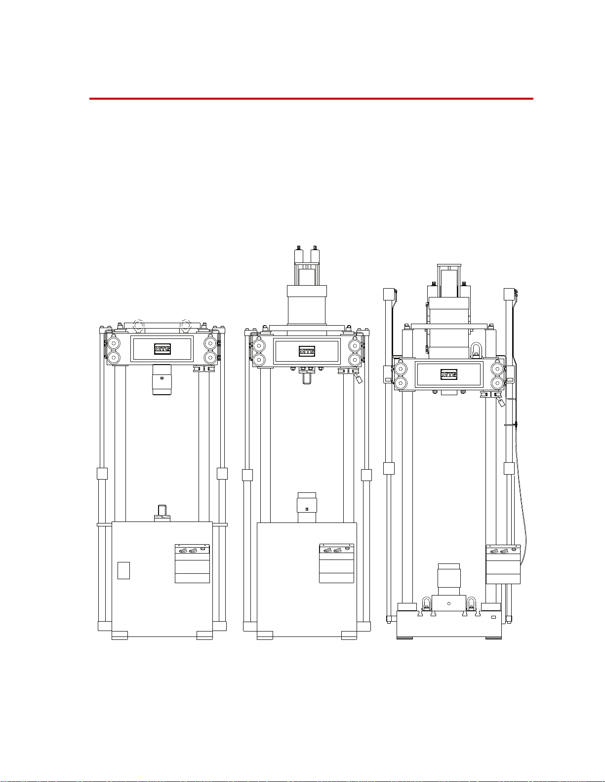
Introduction
Crosshead Mounted ActuatorBase Mounted Actuator Custom T-Slot Baseplate
Contents Component Identification 15
The Series 311 Load Frames are designed to perform high-velocity tension or
compression testing, high-frequency fatigue testing, as well as other tests. The
load frame must be configured with optional actuators, servovalves, force
transducers, grips, and other components from MTS Systems Corporation.
Functional Description 17
Specifications 19
Model 311.31 Load Frame
Series 311 Load Frame Introduction
13

What you
need to know
This manual assumes that you know how to use your system controller. See the
appropriate manual for information about performing any controller-related step
in this manual’s procedures. You are expected to know how to do the following:
• Turn system electrical power on and off.
• Turn hydraulic pressure on and off.
• Manually adjust the actuator position.
• Use your grips and fixtures.
Related products The load frame includes other products. See the following product manuals for
product-specific information and maintenance procedures.
• The Series 111 Accumulator Pr oduct Information manual.
(part number 011-553-300)
• The Series 244 Actuator Product Information manual
(part number 011-551-300)
• The Series 252 Servovalve Product Information manual
(part number 011-182-900)
14
Introduction
Series 311 Load Frame
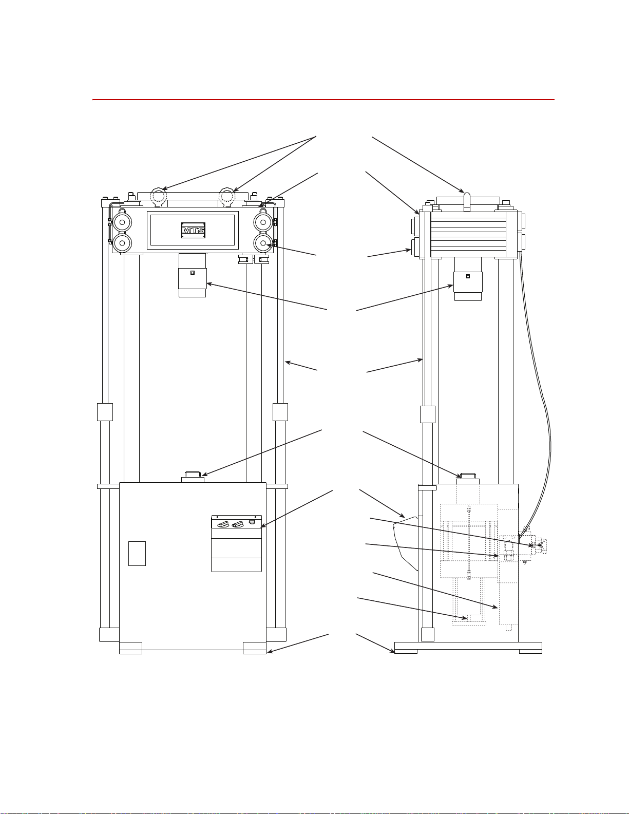
Component Identification
Crosshead
Crosshead
Locks
Crosshead
Lifts
Control
Panel
Isolation
Pads
Actuator
Lifting Rings
Force
Transducer
Manifold
Accumulator
LVDT
Servovalve
Component Identification
Series 311 Load Frame Introduction
15

Component Identification
Item Description
Component Descriptions
Lifting rings
Crosshead
Crosshead locks
Force transducer
Crosshead lifts
Actuator
Control panel
Crosshead lift
control
Crosshead locks
Emergency Stop
Allows the load frame to be moved by lifting the entire load frame.
Moves up and down the columns to accommodate different sized specimens
and fixtures. The crosshead is stiff and light weight; it is one end of the force
train.
Clamps the crosshead to the columns. The crosshead locks are hydraulically
powered.
Measures the axial forces applied to specimen.
Raises and lowers the crosshead hydraulically to accommodate different
specimen sizes. The lifts are small hydraulic actuators.
Applies axial forces to specimens. The actuator is a hydraulically powered
device that provides linear displacement of (or forces into) a specimen. Grips
and fixtures can be mounted to the actuator.
The Emergency Stop button is standard; the other controls are optional. See
“Lift and Lock Controls” on page 42 for more information.
Controls the crosshead lifts to raise and lower the crosshead hydraulically.
Clamps and unclamps the crosshead to lock it in place or to unlock it so the
crosshead can be repositioned.
Removes hydraulic pressure from the load frame and issues an interlock signal
to the controller to stop the test program.
Servovalve
Manifold
Accumulators
LVDT
Isolation pads
Controls both the flow rate and the direction of fluid entering the actuators. It
determines how fast the actuator extends or retracts.
Serves as the junction point between the hydraulic power unit (HPU),
accumulators, servovalve, and actuator. The actuator manifold controls the
hydraulic circuit that connects the hydraulic components.
Stores hydraulic fluid under pressure to increase the actuator’s response time.
Accumulators also minimize line pressure fluctuations. One accumulator
connects to the pressure line; the other to the return line.
Measures the displacement of the actuator’s travel. The linear variable
displacement transducer (LVDT) is located inside the actuator.
Dampens the natural frequency to about 20 Hz. Optional air inflated isolators
dampen the frequency to about 2 Hz.
16
Introduction
Series 311 Load Frame

Functional Description
The load frame is a stand alone testing structure. The following components are
used with the load frame:
• Crosshead lifts and locks
• Actuator
• Servovalves
• Hydraulic manifold
• Transducers
–Force
– Displacement
Load frame The load frame is the basic structure which provides the reaction mass for the
force train. The base of the load frame is one end of the reaction mass and the
crosshead is the other end of the reaction mass. Installing a specimen and other
fixtures or components between the load frame base and the crosshead create a
force train.
Functional Description
The crosshead is mounted above the base by four columns. A control panel lets
you operate the crosshead lifts, locks, and grips to assist in specimen installation
procedures.
Crosshead lifts
and locks
The crosshead can be positioned anywhere along the load frame columns. It is
moved along the column with hydraulic lifts. When the crosshead is in an
appropriate test position, it is hydraulically clamped to that position. This lets
you change the load frame to accommodate specimens of different lengths.
Actuators The actuator can be located in the middle of the load frame base or crosshead. It
is a hydraulically powered piston that applies displacement of (or force into) a
specimen. It can apply equal power in tension and compression. One end of the
test specimen is installed into a fixture which is mounted to the end of the
actuator rod.
Servovalves A servovalves regulates the direction and flow of the hydraulic fluid to and from
a hydraulic actuator. The servovalve responds to the polarity and magnitude of
the command signal generated by the controller.
Hydraulic manifold A hydraulic manifold (also called an actuator manifold or hydraulic service
manifold) controls the hydraulic pressure to the load frame. The manifold
includes solenoid valves that control the hydraulic pressure (off, low, or high).
An actuator manifold is mounted directly to the actuator on the load frame. A
hydraulic service manifold (HSM) is located near the load frame and connects to
the actuator with hydraulic hoses.
Series 311 Load Frame Introduction
17

Functional Description
Transducers The load frame usually includes a force transducer and an LVDT (or other
displacement measurement device.
Force The force transducer (also called load cell or force sensor) measures the amount
of tension or compression and rotational torque appl ied to it. It has four strain
gages that form a balanced Wheatstone bridge. When forces are applied to the
bridge, it becomes unbalanced and produces an electrical signal that is
proportional to the force applied to it. The force transducer is a resistive device
and requires a DC conditioner to process the axial signal from the Wheatstone
bridge.
LVDT The LVDT measures the linear actuator’s travel. The LVDT consists of a
transformer with one primary and two secondary coils wound on a common
cylinder. The coil is stationary inside the actuator. A c ore is attached to the piston
rod of the actuator. As it moves inside the coil, it produces an electrical signal
that represents the position of the piston rod. The phase of the signal indicates the
direction the actuator rod is moving. An LVDT requires an AC conditioner to
process the signal.
18
Introduction
Series 311 Load Frame

Specifications
Specifications
This section provides some of the specifications of the Series 311 Load Frame.
Other specifications can be found on the assembly drawings specific to each load
frame.
Parameter Specification
Force rating
311.11
311.21
311.31
311.41
311.51
311.61
311.71
Crosshead weight
311.11
311.21
311.31
311.41
311.51
311.61
311.71
Total weight
*
311.11
311.21
311.31
311.41
311.51
311.61
311.71
250 kN (55 kip)
500 kN (110 kip)
1000 kN (220 kip)
2500 kN (550 kip)
5000 kN (1100 kip)
7500 kN (1650 kip)
10,000 kN (2200 kip)
approximate weight
180 kg (400 lb)
320 kg (700 lb)
680 kg (1500 lb)
1680 kg (3700 lb)
3175 kg (7000 lb)
5450 kg (12,000 lb)
7300 kg (16,000 lb)
approximate weight
900 kg (2000 lb)
2000 kg (4500 lb)
3500 kg (8000 lb)
8500 kg (19,000 lb)
16,000 kg (36,000 lb)
27,000 kg (60,000 lb)
36,000 kg (80,000 lb)
* The weight specification is for lifting and moving purposes. The weight
includes a typical actuator, force transducer, and grips. The actual
shipping weight must be determined by a scale.
Series 311 Load Frame Introduction
19

Specifications
20
Introduction
Series 311 Load Frame

Safety
General Safety Practices
This section provides information about safety issues that pertain to
servohydraulic systems in general. These issues include statements to the
intended use and foreseeable misuse of the system, the hazard zone, definition for
the graphical hazard labeling that is affixed to your product, and other (more
general) safety information that relates to the high-pressure and highperformance characteristics of MTS servohydraulic systems.
MTS test systems are designed to generate motions and forces and impart these
motions and forces into a test specimen.
When you prepare to operate the system and during system operation, ensure the
following:
• Do not use or allow personnel to operate the system who are not
• Do not disable safety components or features (including limit detectors,
• Do not attempt to operate the system without appropriate personal safety
• Do not apply energy levels that exceed the maximum energies and velocities
• Whenever possible, use tongs or similar device to handle specimens during
• Do not test a specimen that exceeds the minimum (if applicable) or
• Do not use specimens that are combustible, flammable, pressurized, or
• Do not use humans as specimens or allow humans to ride in or on the test
• Do not modify the system or replace system components using parts that are
• Do not operate the system in an explosive atmosphere.
• Do not use the system in a test area where uncontrolled access to the test
• Do not operate the system unless an interlock is installed to monitor supply
experienced, trained, or educated in the inherent dangers associated with
high-performance servo hydraulics and who are not experienced, trained, or
educated with regard to the intended operation as it applies to this test
system.
light curtains, or proximity switches/detectors).
gear (for example, hearing, hand, and eye protection).
for the system design. Refer to the system specifications.
specimen installation.
maximum allowable mass. Refer to the system specifications.
explosive.
specimen or the test system for any purpose unless the system is man-rated
and all associated safety conditions are strictly enforced.
not MTS component parts or effect repairs using parts or components that
are not manufactured to MTS specifications.
system is allowed when the system is in operation.
pressure into the HSM and initiate a system interlock if a low or no pressure
event occurs.
Series 311 Load Frame Safety
21

If you have system related responsibilities (that is, if you are an operator, service
engineer, or maintenance person), you should study safety information carefully
before you attempt to perform any test system procedure.
You should receive training on this system or a similar system to ensure a
thorough knowledge of your equipment and the safety issues that are associated
with its use. In addition, you should gain an understanding of system functions
by studying the other manuals supplied with your test system. Contact MTS for
information about the content and dates of training classes that are offered.
It is very important that you study the following safety information to ensure that
your facility procedures and the system’s operating environment do not
contribute to or result in a hazardous situation. Remember, you cannot eliminate
all the hazards associated with this system, so you must learn and remain aware
of the hazards that apply to your system at all times. Use these safety guidelines
to help learn and identify hazards so that you can establish appropriate training
and operating procedures and acquire appropriate safety equipment (such as
gloves, goggles, and hearing protection).
Each test system operates within a unique environment which includes the
following known variables:
• Facility variables (facility variables include the structure, atmosphere, and
utilities)
• Unauthorized customer modifications to the equipment
• Operator experience and specialization
• Test specimens
Because of these variables (and the possibility of others), your system can
operate under unforeseen circumstances that can result in an operating
environment with unknown hazards.
Improper installation, operation, or maintenance of your system can result in
hazardous conditions that can cause death, personal injury, or damage to the
equipment or to the specimen. Common sense and a thorough knowledge of the
system’s operating capabilities can help to determine an appropriate and safe
approach to its operation.
Safety Practices Before System Operation
Before you apply hydraulic power to the test system, review and complete all of
the safety practices that are applicable to your system. The goal, by doing this, is
to improve the safety awareness of all personnel involved with the system and to
maintain, through visual inspections, the integrity of specific system
components.
Read all manuals Study the contents of this manual and the other manuals provided with your
system before attempting to perform any system function for the first time.
Procedures that seem relatively simple or intuitively obvious can require a
complete understanding of system operation to avoid unsafe or dangerous
situations.
22
Safety
Series 311 Load Frame

Locate and read
hazard placards/labels
Find, read, and follow the hazard placard instructions located on the equipment.
These placards are placed strategically on the equipment to call attention to areas
such as known crush points and electrical voltage hazards.
Locate Lockout/tautog
points
Know facility safe
procedures
Locate Emergency
Stop buttons
Know where the lockout/tagout point is for all of the supply energies associated
with your system. This includes the hydraulic, pneumatic, electric, and water
supplies (as appropriate) for your system to ensure that the system is isolated
from these energies when required.
Most facilities have internal procedures and rules regarding safe practices within
the facility. Be aware of these safe practices and incorporate them into your daily
operation of the system.
Know the location of all the system Emergency Stop buttons so that you can
stop the system quickly in an emergency . Ensure that an Emergency Stop button
is located within 2 meters (6 feet) of the operator at all times.
Know controls Before you operate the system for the first time, make a trial run through the
operating procedures with the power off. Locate all hardware and software
controls and know what their functions are and what adjustments they require. If
any control function or operating adjustment is not clear, review the applicable
information until you understand it thoroughly.
Have first aid available Accidents can happen even when you are careful. Arrange your operator
schedules so that a properly trained person is always close by to render first aid.
In addition, ensure that local emergency contact information is posted clearly and
in sight of the system operator.
Know potential crush
and pinch points
Be aware of potential crush and pinch points on your system and keep personnel
and equipment clear of these areas.
Be aware of
component movement
with hydraulics off
Know electrical
hazards
Remember, when hydraulic power is interrupted on a servohydraulic system, it is
likely that stored accumulator pressure will persist for some time within the
system. In addition, it is likely that as stored energy dissipates, gravity will cause
portions of the system to move.
The crosshead can slowly drift down the columns if the locks are turned off and
when hydraulic pressure is turned off. The crosshead can damage any test
fixtures, grips, and specimen in its path. Unlock the crosshead only to reposition
it. Always lock the crosshead after you have repositioned it and never leave the
crosshead unlocked.
The actuator rod can also drift down when hydraulics are turned off hitting
anything in its path. This uncommanded movement is because of oil movement
between the pressure/return ports and oil blow by across the piston hub. Be aware
that this can happen and clear the area around the actuator rod when hydraulics
are turned off.
When the system electrical power is turned on, minimize the potential for
electrical shock hazards. Wear clothing and use tools that are properly insulated
for electrical work. Avoid contact with exposed wiring or switch contacts.
Whenever possible, turn off electrical power when you work on or in proximity
to any electrical system component. Observe the same precautions as those given
for any other high-voltage machinery.
Series 311 Load Frame Safety
23

Keep bystanders
safely away
Keep bystanders at a safe distance from all equipment. Never allow bystanders to
touch specimens or equipment while the test is running.
Wear proper clothing Do not wear neckties, shop aprons, loose clothing or jewelry, or long hair that
could get caught in equipment and result in an injury. Remove loose clothing or
jewelry and restrain long hair.
Remove flammable
fluids
Know compressed gas
hazards
Remove flammable fluids from their containers or from components before you
install the container or component. If desired, you can replace the flammable
fluid with a non-flammable fluid to maintain the proper proportion of weight and
balance.
Most servohydraulic systems contain accumulators that require a high-pressure
gas precharge (pressures that exceed 138 bar [2000 psi]). In addition, some
systems can contain devices, such as static supports, that are pneumatically
operated. High-pressure devices are potentially dangerous because a great
amount of energy is available in the event of an uncontrolled expansion or
rupture.
Observe the following safety practices when you work with high-pressure air or
gases:
• When you charge an accumulator, follow all the charging instructions
provided in the appropriate product information manuals. When precharging
accumulators, properly identify the type of gas to be used and the type of
accumulator to be precharged.
Use only dry-pumped nitrogen to precharge nitrogen-charged accumulators.
(Dry-pumped nitrogen can also be labeled “oil pumped” or “dry water
pumped.”) Do not use compressed air or oxygen for precharging: the
temperature increase caused by rapid gas compression can result in highly
explosive conditions when hydraulic fluid is in the presence of oxygen or
compressed air.
24
Safety
• Always follow the recommended bleeding procedures before you remove or
disassemble components that contain pressurized gas. When you bleed a gas
or remove a fitting, hose, or component that contains a gas, remember that
many gases cannot support life. Therefore, as the ratio of released gas to
oxygen increases, so does the potential for suffocation.
• Wear appropriate safety devices to protect your hearing. Escaping air or gas
can create a noise level that can damage your hearing.
Series 311 Load Frame

• Ensure that all pressurized air or gas is bled out of a pneumatic or gas-
charged device before you start to disassemble it. A thorough understanding
of the assembly and its pressurized areas is necessary before you undertake
any maintenance. Refer to the appropriate product information for the
correct bleeding procedure.
It might not be obvious or intuitive which bolts or fittings are used to
restrain a pressurized area. On some assemblies, you must remove a cover
plate to gain access to the structural bolts. Sometimes, to protect you from a
rapid release of trapped gases, a small port is exposed when you remove this
cover plate. Exposing this port ensures that the gas precharge is fully bled
before disassembly. However, this is not the recommended procedure for
bleeding a pneumatic or gas-charged device, because it can expose you to
the dangers of escaping compressed gas and particulates that are expelled
from the chamber or around the seals. Do not assume that cover plates and
ports are installed in all the critical locations.
Consult MTS when in doubt about the safety or reliability of any system-related
procedure or modification that involves devices that contain any type of
compressed gas.
Check bolt ratings and
torques
Practice good
housekeeping
Protect hoses and
cables
To ensure a reliable product, fasteners (such as bolts and tie rods) used in MTSmanufactured systems are torqued to specific requirements. If a fastener is
loosened or the configuration of a component within the system is modified, refer
to the system and component assembly drawings (located on the System
Documentation CD) to determine the correct fastener, fastener rating, and torque.
Overtorquing or undertorquing a fastener can create a hazardous situation due to
the high forces and pressures present in MTS test systems.
On rare occasions, a fastener can fail even when it is correctly installed. Failure
usually occurs during torquing, but it can occur several days later. Failure of a
fastener can result in a high velocity projectile. Therefore, it is a good practice to
avoid stationing personnel in line with or below assemblies that contain large or
long fasteners.
Keep the floors in the work area clean. Hydraulic fluid that is spilled on any type
of floor can result in a dangerous, slippery surface. Do not leave tools, fixtures,
or other items not specific to the test, lying about on the floor, system, or decking.
Protect electrical cables from spilled hydraulic fluid and from excessive
temperatures that can cause the cables to harden and eventually fail. Ensure that
all cables have appropriate strain relief devices installed at the cable and near the
connector plug. Do not use the connector plug as a strain relief.
Protect all system hoses and cables from sharp or abrasive objects that can cause
the hose or cable to fail. Never walk on hoses or cables or move heavy objects
over them. Consider hydraulic distribution system layout and route hoses and
cables away from areas that expose them to possible damage.
When removing hydraulic hoses for equipment repair or changing testing
components (for example, hydraulic grips), make sure to cap the hose ends to
avoid spilling hydraulic fluid.
Series 311 Load Frame Safety
25

Provide proper
hydraulic fluid
filtration.
If the system is equipped with a non-MTS hydraulic power unit, ensure proper
filtration to the hydraulic distribution system and testing component s. Particles
present in hydraulic fluid and cause erratic or poor system response.
Protect accumulators
from moving objects.
Protect accumulators with supports or guards. Do not strike accumulators with
moving objects. This could cause the accumulator(s) to separate from the
manifold resulting in equipment damage and personal injury.
Record changes If you change any operating procedure, write the change and the date of the
change in the appropriate manual.
Provide test area
guards
Do not exceed the
Maximum Supply
Pressure
Do not disable safety
devices
Use appropriately
sized fuses
Use protective guards such as cages, enclosures, and special laboratory layouts
when you work with hazardous test specimens (for example, brittle or
fragmenting materials or materials that are internally pressurized).
For standard MTS systems, ensure that hydraulic supply pressure is limited to a
maximum 21 MPa (3000 psi). If you system has a custom application that
requires higher pressure, make sure you limit supply pressure to that rated for the
custom components.
Your system might have active or passive safety devices installed to prevent
system operation if the device indicates an unsafe condition. Do not disable such
devices as it can result in unexpected system motion.
Whenever you replace fuses for the system or supply, ensure that you use a fuse
that is appropriately sized and correctly installed. Undersized or oversized fuses
can result in cables that overheat and fuses that explode. Either instance creates a
fire hazard.
Provide adequate
lighting
Provide means to
access out-of-reach
components
Ensure equipment is
secure
Ensure adequate lighting to minimize the chance of operation errors, equipment
damage, and personal injury. You need to see what you are doing.
Make sure you can access system components that might be out of reach while
standing on the floor. For example ladders or scaffolding might be required to
reach load cell connectors on tall load units.
Make sure the equipment is secure or provide vibration isolation. Some testing
can be performed at resonant frequencies that might cause the equipment to
vibrate and move during testing.
Safety Practices While the System Is in Operation
Wear appropriate
personal protection
Wear eye protection when you work with high-pressure hydrau lic fluid,
breakable specimens, or when anything characteristic to the specimen could
break apart.
W ear ear protection when you work near electric motors, pumps, or other devices
that generate high noise levels. Some systems can create sound pressure levels
that exceed 70 dbA during operation.
W ear appropriate personal protection equipment (gloves, boots, suits, respirators)
whenever you work with fluids, chemicals, or powders that can irritate or harm
the skin, respiratory system, or eyes.
26
Safety
Series 311 Load Frame

Provide test area
guards
Use protective guards such as cages, enclosures, and special laboratory layouts
when you work with hazardous test specimens (for example, brittle or
fragmenting materials or materials that are internally pressurized).
Specimen temperature
changes
Handle chemicals
safely
Know servohydraulic
system interlocks
During cyclic testing, the specimen temperature can become hot enough to cause
burns. Wear personal protection equipment (gloves) when handling specimens.
Whenever you use or handle chemicals (for example, cleaning fluids, hydraulic
fluid, batteries, contaminated parts, electrical fluids, and maintenance waste),
refer to the appropriate MSDS documentation for that material and determine the
appropriate measures and equipment required to handle and use the chemical
safely. Ensure that the chemical is disposed of appropriately.
Interlock devices should always be used and properly adjusted. Interlock devices
are designed to minimize the chance of accidental damage to the test specimen or
the equipment. Test all interlock devices for proper operation immediately before
a test. Do not disable or bypass any interlock devices as doing so could allow
hydraulic pressure to be applied regardless of the true interlock condition. The
Reset/Override button is a software function that can be used to temporarily
override an interlock while attempting to start the hydraulic power unit and gain
control of the system.
Know system limits Never rely on system limits such as mechanical limits or software limits to
protect you or any personnel. System limits are designed to minimize the chance
of accidental damage to test specimens or to equipment. T est all limits for proper
operation immediately before a test. Always use these limits and adjust them
properly.
Do not disturb sensors Do not bump, wiggle, adjust, disconnect, or otherwise disturb a sensor (such as
an accelerometer or extensometer) or its connecting cable when hydraulic
pressure is applied.
Ensure secure cables Do not change any cable connections when electrical power or hydraulic pressure
is applied. If you attempt to change a cable connection while the system is in
operation, an open control loop condition can result. An open control loop
condition can cause a rapid, unexpected system response which can result in
severe personal injury, death, or damage to equipment. Also, ensure that all
cables are connected after you make any changes in the system configuration.
Stay alert A void long periods of work without adequate rest. In addition, avoid long periods
of repetitious, unvarying, or monotonous work because these conditions can
contribute to accidents and hazardous situations. If you are too familiar with the
work environment, it is easy to overlook potential hazards that exist in that
environment.
Contain small leaks Do not use your fingers or hands to stop small leaks in hydraulic or pneumatic
hoses. Substantial pressures can build up, especially if the hole is small. These
high pressures can cause the oil or gas to penetrate your skin, causing painful and
dangerously infected wounds. Turn off the hydraulic supply and allow the
hydraulic pressure to dissipate before you remove and replace the hose or any
pressurized component.
Series 311 Load Frame Safety
27

Stay clear of moving
equipment/avoid crush
points
Stay clear of mechanical linkages, connecting cables, and hoses that move
because you can get pinched, crushed, tangled, or dragged along with the
equipment. High forces generated by the system can pinch, cut, or crush anything
in the path of the equipment and cause serious injury. Stay clear of any potential
crush points. Most test systems can produce sudden, high-force motion. Never
assume that your reactions are fast enough to allow you to escape injury when a
system fails.
Know the causes of
unexpected actuator
motions
Do not use RF
transmitters
Hazard Icons
Icon Description
The high force and velocity capabilities of MTS actuators can be destructive and
dangerous (especially if actuator motion is unexpected). The most likely causes
of unexpected actuator response are operator error and equipment failure due to
damage or abuse (such as broken, cut, or crushed cables and hoses; shorted wires;
overstressed feedback devices; and damaged components within the servocontrol
loop). Eliminate any condition that could cause unexpected actuator motion.
Keep radio frequency (RF) transmitters away from the workstation computers,
remote terminals, and electronics consoles. Intense RF fields can cause erratic
operation of the more sensitive circuits in the system.
Following are the typical hazard icons used on MTS load units.
Moving parts; pinch points. Keep clear of areas
noted with this label
Part number 57-230-011.
28
Safety
High pressure fluid or gasses. Do not tamper with
fittings or hoses.
Part number 57-230-006.
Possible tipping hazard. The machine should only
be moved by qualified riggers familiar with moving
heavy, delicate equipment. Once in final operation
position, the frame should be bolted to a suitable
reaction mass.
Part number 572300-29.
Series 311 Load Frame

Icon Description
Do not climb on machine.
Part number 57-230-037.
Read the manuals or instructions. Become familiar
with safety information. Also become familiar with
operating and maintenance information.
Part number 57-237-501.
Possible explosive or flying debris. Wear
appropriate protection such as safety goggles and
hearing protection.
Part number 57-237-506.
Lift point.
Part number 572375-13.
Additional Hazard Labels
This section provides information on additional hazard labeling typically
included on load units. Because of the various configurations of the 311 Load
Unit, the presence or location shown in the following figures might be different
on your particular load unit. Part numbers are provided should replacement labels
be necessary due to damage.
Series 311 Load Frame Safety
29

Base Assembly
View A-A
1
1
2
3
4
5
Item Part Number Description
1
2
3
4
5
045-384-101 Warning. High force moving parts. Can cause severe injury or
equipment damage.
Stay clear and use eye protection while test is in progress.
Read instructions before operating or servicing.
037-588-901 Identification label. Includes model number, part number, serial
number, force capacity, and manufacture date.
050-275-301 Information label. No step.
050-275-201 Caution. Heavy control panel (up to 15 kg/30 lbs). Can cause
personal injury or equipment damage.
Support control panel until bolts are out. Let down slowly.
005-905-101 Warning. If lift cylinder line is opened, air may enter causing
crosshead to drop when unlocked. Bleed both cylinders before
unlocking crosshead.
30
Safety
Series 311 Load Frame

Cylinder Assembly
1
2
Item Part Number Description
1
2
037-588-801 Identification label. Includes model number, serial number,
assembly number, force, effective date, static stroke, dyn stroke,
and hydrostatic bearing.
038-202-801 Warning. Subjecting this equipment to working pressure above
3000 psi (21 MPa) can result in component rupture and injury to
personnel. See the product manual for safety precautions before
operating.
Series 311 Load Frame Safety
31

Crush Point Hazards
Crush
Zones
It is important to stay clear of any potential crush points when the system is
operating. You should know where the crush points are in your system and
protect yourself and others from those crush points with appropriate safety
devices. The following paragraphs describe crush points and precautions to take
while working around crush points.
32
Locations A crush point exists between the platen and crosshead on load frames where the
actuator piston rod and specimen move (both areas are shown). Another potential
crush point exists where the lower end of the actuator piston rod extends below
the platen and the bottom of the load frame/load frame.
Precautions Keep clear of any mechanical linkage that moves within a closed area. If the
linkage should move (when the system starts or due to mechanical failure), very
high forces can be present that could pinch, cut, or crush anything in the path of
linkage movement.
Safety
Never allow any part of your body to enter the path of machine movement or to
touch moving machinery, linkages, hoses, cables, specimens, etc. These present
serious crush points or pinch points.
Series 311 Load Frame

Installation
Contents Unpacking the Load Frame 34
Prerequisite You will need a fork lift or overhead crane capable of lifting the load frame.
This section describes how to install the Series 311 Load Frame.
Connecting Cables 38
Connecting Hydraulics 39
Removing the Shipping Collars 40
Ensure the lifting equipment can accommodate the weight of the load frame, see
the following table.
Series 311 Load Fame Weights
Model Weight
311.11 900 kg (2000 lb)
311.21 2000 kg (4500 lb)
311.31 3500 kg (8000 lb)
311.41 8500 kg (19,000 lb)
311.51 16,000 kg (36,000 lb)
311.61 27,000 kg (60,000 lb)
311.71 36,000 kg (80,000 lb)
Procedure Perform the following to install the load frame.
1. Unpack the load frame. Go to “Unpacking the Load Frame” on page 34 to
unpack and move the load frame.
2. Connect the cables between the load frame and controller. Go to
“Connecting Cables” on page 38 to make the various controller connections.
Return to this procedure when done.
3. Connect the hydraulic hoses between the load frame and hydraulic service
manifold. Go to “Connecting Hydraulics” on page 39 to connect the load
frame to your hydraulic supply system. Return to this procedure when done.
4. Remove the collars on the columns so the load frame can be used. Go to
“Removing the Shipping Collars” on page 40 to complete the installation
procedure.
Series 311 Load Frame Installation
33

Unpacking the Load Frame
WARNING
Wooden
Pallet
Protective Wrapping
Strap
Eyebolt
Unpacking the Load Frame
Required equipment The load frame is shipped horizontally on a wooden pallet. You will need the
following equipment to unpack the load frame:
• Lifting slings—not chains—to lift the load frame from its pallet
• Lifting chains to tip the load frame upright
• Rubber mats for the load frame’s feet to rest on
• Wooden blocks for the load frame’s columns to rest on
• A knife to cut the packing straps
The load frame is extremely heavy.
The weight of the load frame can seriously hurt you and damage your load
frame.
Do not allow the load frame to drop or topple.
• Ensure that your chains, slings, and crane have a working capacity greater
than the load frame’s weight (see “Series 311 Load Fame Weights” on page
33).
• Ensure that the lifting eyebolts are tight.
• Ensure that the crosshead locking bolts are fully tightened.
• Lift the load frame only high enough to clear its pallet.
• Operate the crane smoothly to prevent sudden shocks to the sling.
1. Unpack the load frame from its shipping container.
Cut the packing straps and remove any bolts as needed. Make sure the
lifting eyebolts are tight (two eyebolts are located on the crosshead).
34
Installation
Unpacking the Load Frame
Series 311 Load Frame

Unpacking the Load Frame
2. Inspect the load frame for shipping damage.
Look for the following:
• Scratches in the load frame or columns
• Damaged electrical connections
• Damaged hydraulic connections
• Dents and other structural damage
• Torn, kinked, or breaking hoses
Report any damage found to both the carrier and MTS. In the U.S. and
Canada, call the MTS HELPLine at 1-800-328-2255. Elsewhere, contact
your local MTS office.
3. Clamp the crosshead.
Normally, the crosshead is locked in place for shipping purposes. Ensure the
crosshead is clamped in place; check that the shipping collars are on
diagonally opposite columns directly above and below the crosshead. Refer
to the following table for the torque specifications.
Shipping Collar Torque Specifications
*
Model Shipping Collar Torque
311.11 75 N•m (55 lbf•ft)
311.21 110 N•m (80 lbf•ft)
311.31 150 N•m (110 lbf•ft)
311.41 270 N•m (200 lbf•ft)
311.51 920 N•m (680 lbf•ft)
* Contact MTS Systems Corporation for torque specifications for the
Model 311.61 and Model 311.71 Load Frames.
4. Tip the load frame upright.
A. Attach the chains to the lifting eyebolts. Move the crane/forklift to keep
the chains as straight as possible. When attaching both eye bolts to the
same point, do not exceed a 30° chain angle as shown in the following
figure. Exceeding a 30° chain angle causes undesired stress or strain on
the eye bolts or hoist rings.
Series 311 Load Frame Installation
35

Unpacking the Load Frame
Crane Travel
30° Maximum
30° maximum when
connecting both eye
bolts to a single point.
B. Slowly raise the load frame to its upright position. As the unit rises,
keep moving the crane to keep the chains as straight as possible.
36
Installation
C. When the load frame is upright, raise it slightly to clear the shipping
pallet.
5. Move the load frame to its final location.
Before you move the load frame review the following:
• The floor where the load frame will sit can bear its weight (see “Series
311 Load Fame Weights” on page 33).
• The path to the load frame’s destination is clear and uncluttered.
• The area where the load frame will sit is clean and well lit, with all
hoses and cables moved out of harm’s way.
• The eyebolts are tight.
• The crosshead shipping collars are properly torqued.
Lift the load frame only as high as necessary. Move it slowly to its
installation site.
Series 311 Load Frame

Unpacking the Load Frame
Load Unit
Install
Shims
to Level
Floor
Isolation Pads
6. Place the load frame onto the isolation pads.
Install stock metal shims between the pads and the floor.
7. Clean the columns.
Some load frame columns are wrapped with protective paper. Remove the
paper as needed. All load frame columns are covered with a protective
grease. Remove the grease using a grade #1 kerosene, mineral spirits, or
equivalent petroleum-based solvent. Ensure adequate ventilation when
cleaning the columns, see the solvent container for additional warnings and
cautions.
8. Remove the chains.
Series 311 Load Frame Installation
37

Connecting Cables
Ê
Ë
Ì
Í
Î
Ê
Ë
Ì
Í
Î
Connecting Cables
Your controller manual should have cabling information about the connections
described in this section. Most controller manuals provide the signal pinouts of
the connector and assembly numbers for standard MTS cables.
Note Many of the cables are connected to optional equipment. The following
Prerequisite You must have either a cable assembly drawing of your test system, or you must
know the system controller well enough to determine each type of cable
connection.
procedure shows the most common connections. The exact connector
locations vary quite a bit among the various models of the load frame.
38
Installation
1. The force transducer is connected to a DC conditioner in the controller.
2. The ground connection is located on the back of the control panel. This is
usually connected to a chassis ground on a console or the controller chassis.
3. The load frame control panel is connected to the controller chassis. It
contains the emergency stop and crosshead lock signals.
4. The servovalve is connected to a valve driver in the controller.
5. The displacement sensor (also called an linear variable displacement
transducer or LVDT) is connected to an AC conditioner in the controller.
Series 311 Load Frame

Connecting Hydraulics
The procedure describes how to connect the load frame to the hydraulic power
source. The load frame can be connected directly to the hydraulic power unit
(also called HPU), to hydraulic plumbing in the workplace, or through a
hydraulic service manifold (HSM).
Note The internal hydraulic connections from the actuator manifold and
accessories such as the hydraulic lifts and locks should already be
made.
The load frame actuator usually has a manifold mounted to it. The manifold
connects the ports on each end cap to the ports for a servovalve. The hydraulic
connection are made at this manifold.
1. Connect the return line from the hydraulic power source to the hydraulic
port on the manifold labeled “R”.
2. Connect the pressure line from the hydraulic power source to the hydraulic
port on the manifold labeled “P”.
Connecting Hydraulics
3. Connect the drain line from the hydraulic power source to the hydraulic port
on the manifold labeled “D”.
4. Turn on the HPU and check for any hydraulic pressure leaks.
5. Select low pressure for the load frame and check for hydraulic leaks in the
load frame.
6. Select high pressure for the load frame and check for hydraulic leaks in the
load frame.
7. Bleed the air out of the hydraulic lift cylinders. See “Bleeding the Hydraulic
Lift Cylinders” on page 56.
8. Return to the installation procedure.
Series 311 Load Frame Installation
39

Removing the Shipping Collars
CAUTION
Removing the Shipping Collars
When the load frame is shipped, the crosshead is clamped in position with
shipping collars.
The collars should not be removed unless the lift cylinders have been bled, full
hydraulic power has been applied to the crosshead, and the crosshead lock
control is in the lock position.
Once the collars have been removed, they should be kept rather than discarded.
The collars can be installed on the columns below the crosshead and used as
stops to limit the crosshead travel should the crosshead fall. The collars are also
used to mechanically restrain the crosshead during some maintenance
procedures.
The crosshead can slowly drift down the columns if the locks are turned off
and when hydraulic pressure is turned off.
The crosshead can damage any test fixtures, grips, and specimen in its
path.
Unlock the crosshead only to reposition it. Always lock the crosshead after you
have repositioned it and never leave the crosshead unlocked.
Note If the shipping collars are being used as stops to limit the crosshead
travel should the crosshead fall, they should be removed before
positioning the crosshead and reinstalled after the crosshead has been
repositioned.
40
Installation
Series 311 Load Frame

Operation
Contents Lift and Lock Controls 42
This section describes how to use the Series 311 Load Frame.
Crush Point Hazards 43
Installing a Specimen 44
Series 311 Load Frame Operation
41
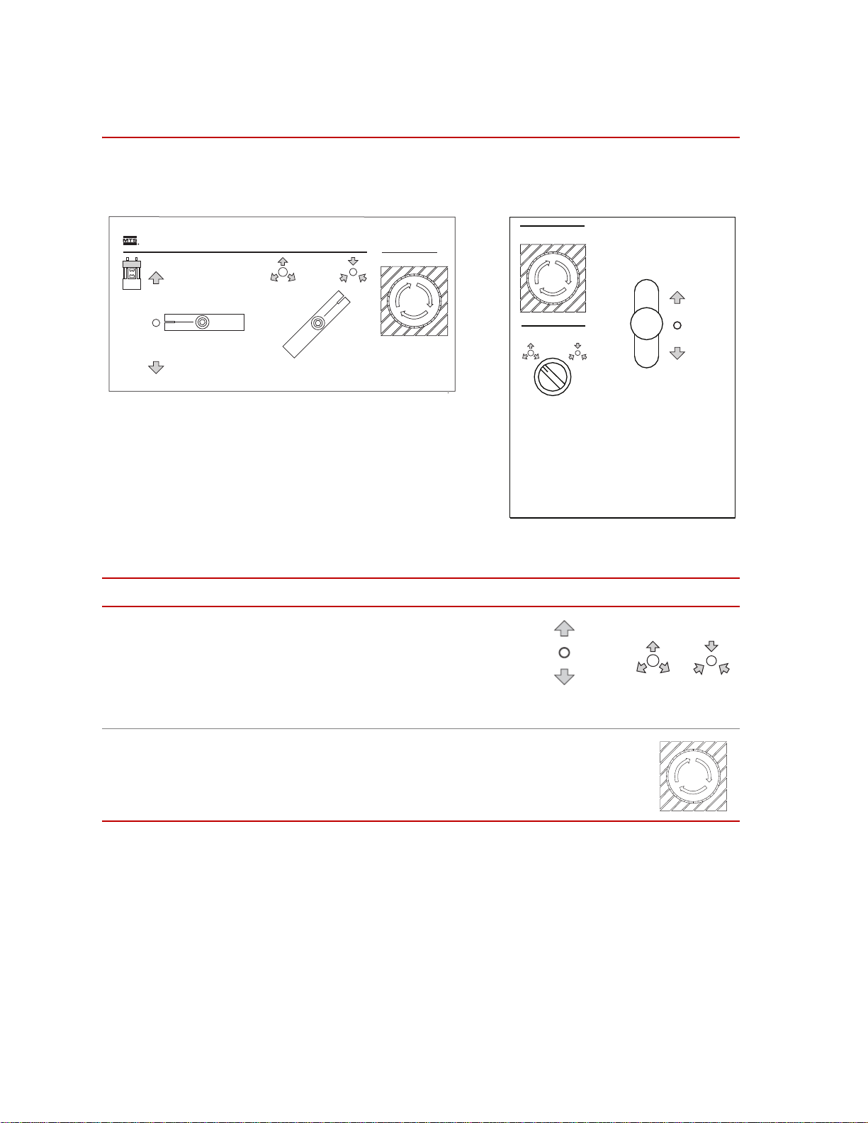
Lift and Lock Controls
Emergency Stop
Crosshead Lift / Lock Control
m
Emergency Stop
Locks
Crosshead
Controls
Up
Stop
Down
Unclamp Clamp
Lift and Lock Controls
The crosshead lift and lock controls for the load frame are located on the front of
the load frame. Two types of control panels are used.
Series 311 Load Frame Controls
Control Description
Crosshead Lift/Lock
Controls
Controls the movement and clamping of the
crosshead. The left handle raises and lowers
the crosshead. The right handle clamps and
unclamps the crosshead to lock or unlock it.
The crosshead must not be moved while it
is clamped. See “Installing a Specimen” on
page 44 for procedures using these controls.
Emergency Stop
Shuts down the hydraulic pressure and stops the test program.
Press this button to shut down hydraulic power, and twist the
switch clockwise to release it. Use the Emergency Stop button
to shut down your test if something unexpected should happen.
42
Operation
Series 311 Load Frame

Crush Point Hazards
Crush
Zones
It is important to stay clear of any potential crush points when the system is
operating. You should know where the crush points are in your system and
protect yourself and others from those crush points with appropriate safety
devices. The following paragraphs describe crush points and precautions to take
while working around crush points.
Crush Point Hazards
Locations A crush point exists between the platen and crosshead on load frames where the
actuator piston rod and specimen move (both areas are shown). Another potential
crush point exists where the lower end of the actuator piston rod extends below
the platen and the bottom of the load frame/load frame.
Precautions Keep clear of any mechanical linkage that moves within a closed area. If the
linkage should move (when the system starts or due to mechanical failure), very
high forces can be present that could pinch, cut, or crush anything in the path of
Series 311 Load Frame Operation
linkage movement.
Never allow any part of your body to enter the path of machine movement or to
touch moving machinery, linkages, hoses, cables, specimens, etc. These present
serious crush points or pinch points.
43

Installing a Specimen
CAUTION
Installing a Specimen
The procedure to install a specimen varies due to the variety of test fixtures,
grips, and the type of specimen being installed. This section should be considered
a guideline. You need to modify this procedure to suit your equipmen t.
Prerequisite You must have the necessary grips and/or fixturing installed. You must also have
the controller set up to control the actuator movement, and you must have a test
program defined.
Procedure 1. Set things up for specimen installation.
A. Ensure that the crosshead is locked.
B. Turn on system electrical power.
C. Turn on high hydraulic pressure.
D. Adjust the actuator to its start position (usually mid-displacement). The
starting position of the actuator depends on the type of fixtures, grips,
and the test being set up.
The crosshead can slowly drift down the columns if the locks are turned off
and when hydraulic pressure is turned off.
The crosshead can damage any test fixtures, grips, and specimen in its
path.
Unlock the crosshead only to reposition it. Always lock the crosshead after you
have repositioned it, and never leave the crosshead unlocked.
2. Set the crosshead position.
The crosshead position depends on the length of the specimen being tested,
the starting position of the actuator, and the size of the fixtures or grips
being used.
A. This step pressurizes the lift actuators. The crosshead might have
shifted position while hydraulic pressure was turned off.
Briefly turn the Crosshead Lift/Lock Controls to the lift
crosshead position to apply a slight upward pressure to the
crosshead.
Then return the lift control to the stop position.
B. Use the Crosshead Lift/Lock Controls to unclamp the
crosshead. Wait 30 seconds for the pressure in the crosshead
locks to drop to zero.
44
Operation
Series 311 Load Frame

Installing a Specimen
Note Always lower the crosshead to where you want it. The pressure
remaining in the lift cylinders after raising the crosshead can slightly shift
its alignment. Lowering the crosshead to its final position removes this
pressure and improves alignment.
C. Use the Crosshead Lift/Lock Controls to move the crosshead
to a point where you can install the specimen (or specimen
fixture) into the upper grip or fixture without obstruction.
Set the control to the stop position “O” before proceeding.
D. Use the Crosshead Lift/Lock Controls to clamp the
crosshead to lock it in its current position. Wait 30 seconds
for the locks to fully clamp the columns.
3. Install the specimen into the grips or fixtures.
Specimen installation will vary according to the type of grip or fixture being
used. If grips are not used then the specimen is installed in a special fixture
designed for a specific specimen to be installed in a specific load frame.
See the appropriate grip manual or fixture drawings for installation
instructions. MTS manufactures a variety of grips:
Note Hydraulically controlled grips require a Series 685 Hydraulic Grip Supply.
• The Series 641 Hydraulic Wedge Grips (hydraulically controlled) are
specifically designed for static or fatigue testing applications. They are
available with a self aligning feature.
• The Series 643.6X Tension/Compression Grips (mechanical) are used
for testing threaded-end and button-end specimens in tension,
compression, or tension/compression.
• The Series 646 Hydraulic Collet Grips (hydraulically controlled) are
designed to perform in a wide variety of testing applications (for
example, high and low cycle fatigue, tension, and compression).
• The Series 647 Hydraulic Wedge Grips (hydraulically controlled) are
specifically designed for static or fatigue testing applications. There are
a variety of configurations of this grip.
• The Series 649 Wedge Grips are specifically designed for static or
fatigue testing applications. These are a mechanical version of the
Series 647 Hydraulic Wedge Grips.
Each type of grip requires the specimen or specimen fixture to fit properly
into the grip.
Series 311 Load Frame Operation
45

Installing a Specimen
46
Operation
Series 311 Load Frame

Maintenance
Contents Maintenance Intervals 51
This section describes the procedures which must be periodically performed to
ensure the continued safe and effective operation of your load frame. The
maintenance interval table on page 51 shows a schedule to maintain your load
frame.
Making Daily Inspections 52
Cleaning the Columns 53
Preventing Rust 54
Checking the Accumulators’ Precharge 55
Bleeding the Hydraulic Lift Cylinders 56
Adjusting the Hydraulic Locks 59
Aligning the Force Transducer 61
Series 311 Load Frame Maintenance
47

Routine Maintenance Overview Checklist
Routine Maintenance Overview Checklist
Recommended service to be performed at each running time interval noted
Calendar Time using 8 hour Running Time
Daily Weekly Biweekly Annually
rate per day
Running Time-Hours 8 40 80 500 1000 1,500 2,000
Check Actuator Platen Area to be Clean
Monitor Filter Indicators X
Check hazard labels for legibility X
Check Hoses/Cables/Connectors X
Check Crosshead/Lifts/Supports X
Check Actuator to be Dry X
Check Hydraulic Service Manifold X
Check Lift Seal Condition to be Dry X
Check Lock Seal Condition to be Dry X
Bionix Lubricate Axial/Torsional Spline
(75-100 hrs)
Check Actuator X
Crosshead/Load Frame
X
*
X
Check Crosshead/Lifts/Supports
Lift Seal Condition is Dry MTS MTS MTS MTS MTS
Lock Seal Condition is Dry MTS MTS MTS MTS MTS
Crosshead Columns are Clean MTS MTS MTS MTS MTS
Column Abrasions are Acceptable MTS MTS MTS MTS MTS
Crosshead Speed is Appropriate MTS MTS MTS MTS MTS
Crosshead Unlock Causes Program
Interlock
Load frame Support Airbags/Pads MTS MTS MTS MTS MTS
Crosshead Movement is Smooth MTS MTS MTS MTS MTS
Hydraulic Crosshead Locks are
Functioning Properly
Bleed Crosshead Lift Cylinders MTS MTS
Lubricate Manual Crosshead Lock Bolts MTS
†
MTS
MTS MTS MTS MTS MTS
MTS MTS MTS MTS
MTS MTS
48
Maintenance
Series 311 Load Frame

Routine Maintenance Overview Checklist
Recommended service to be performed at each running time interval noted
Calendar Time using 8 hour Running Time
Daily Weekly Biweekly Annually
rate per day
Running Time-Hours 8 40 80 500 1000 1,500 2,000
Actuator
Cursory Check of Actuator MTS MTS MTS MTS
Actuator Area is Dry MTS MTS MTS MTS
Actuator Platen Area is Clean MTS MTS MTS MTS
Piston Rod Wear is Acceptable MTS MTS MTS MTS
Bionix Lubricate Axial/Torsional Spline
(75-100 hrs)
Hydraulic Service Manifold
Cursory Check of Hydraulic Service
Manifold
Monitor Filter Indicators MTS MTS MTS MTS
Manifold Hose Connections are Tight MTS MTS MTS MTS
Accumulator Connections are Dry MTS MTS MTS MTS
Accumulator Connections are Tight MTS MTS MTS MTS
Accumulator Caps/Guards are Present MTS MTS MTS MTS
Oil on the Gas Side of the Piston MTS MTS MTS MTS
Check and Adjust Pressure in
Accumulator
Change Filters MTS
Low Pressure Adjustment (Model 294) MTS
Hoses/Cables
Cursory Check of Hoses/Cables/
Connectors
MTS MTS MTS MTS
MTS MTS MTS MTS
MTS MTS MTS MTS
MTS MTS MTS MTS
Absence of Hose Abrasions, Blisters,
Vulcanizing
Cable Condition and Routing is
Acceptable
Check Transducer Connections MTS MTS MTS MTS
Hose Connections and Crimps are Dry MTS MTS MTS MTS
Complete System
Overall System Condition is Acceptable
to Use
Turning Parameters are Appropriate/
System Stable
Series 311 Load Frame Maintenance
MTS MTS MTS MTS
MTS MTS MTS MTS
MTS MTS MTS MTS
MTS MTS MTS MTS
49

Routine Maintenance Overview Checklist
Recommended service to be performed at each running time interval noted
Calendar Time using 8 hour Running Time
Daily Weekly Biweekly Annually
rate per day
Running Time-Hours 8 40 80 500 1000 1,500 2,000
E-Stop is Working if Applicable MTS MTS MTS MTS
Response to Full Stroke Waveform,
Visual and Audible
Valve Balance check displacement
control
Valve Dither Response MTS MTS MTS MTS
Grips
Cursory Check of Grips/Grip Control MTS MTS MTS MTS
Grip Supply Connections are Dry MTS MTS MTS MTS
Grip Seals are Dry MTS MTS MTS MTS
Grip Action is Acceptable MTS MTS MTS MTS
Lubricate Grip Inserts MTS MTS MTS MTS
*Symbol denotes services performed by equipment operators. Most of these procedures involve visual checks
that should not interfere with test system operation. These checks are also completed by trained field service
engineers on each Routine Maintenance visit.
†Symbol denotes service performed by trained field service engineers as part of an MTS Routine Maintenance
plan. Some of these procedures require special service tools and/or specific service training to complete.
MTS MTS MTS MTS
MTS MTS MTS MTS
50
Maintenance
Series 311 Load Frame

Maintenance Intervals
The following table lists the recommended interval for each of these procedures.
Maintenance Intervals
What to Do When to Do It
Making daily inspections
Cleaning the load frame
columns
Preventing rust
Before the start of each day’s testing. See “Making Daily Inspections” on
When the columns become greasy or
dirty.
Depends on the operating environment;
more often in humid environments.
Checking the
accumulators’ precharge
pressures
Bleeding the hydraulic
lift cylinders
At least once a month; more often as
required by operating conditions.
When the crosshead begins to move
roughly; if the sealed side of the
hydraulic supply is opened to air.
Replacing the hydraulic
lift cylinder seals
Adjusting the hydraulic
locks
Replacing the hydraulic
lock seals
†
†
When hydraulic fluid begins leaking out
of the lift cylinders.
When the crosshead sticks or moves
jerkily on the column.
When hydraulic fluid begins leaking
from the locks.
How to Do It
*
page 52.
See “Cleaning the Columns” on page
53.
See “Preventing Rust” on page 54.
See “Checking the Accumulators’
Precharge” on page 55.
See “Bleeding the Hydraulic Lift
Cylinders” on page 56.
Contact MTS Systems Corporation to
schedule service.
See “Adjusting the Hydraulic Locks”
on page 59.
Contact MTS Systems Corporation to
schedule service.
Aligning the force
transducer
After installing the actuator or force
transducer; when a better alignment
See “Aligning the Force Transducer”
on page 61.
between the two is desired.
Servicing the actuator
†
When the actuator begins leaking
(see your actuator manual)
hydraulic fluid or its performance
becomes poor.
For maintenance items listed that do not have a corresponding procedure in this manual, call the MTS
*
HELPLine.
† This cannot be repaired by the customer; call the MTS HELPLine.
Series 311 Load Frame Maintenance
51

Making Daily Inspections
Making Daily Inspections
Before the start of each day’s testing, do a quick inspection of your load frame.
Following are typical things that should be checked daily:
• Ensure that there are no leaks from the hydraulic lifts or locks.
• Ensure that there are no leaks from the actuator , hydraulic service manifold,
servovalve, or accumulators.
• Ensure that electrical connections are tight, with no frayed or poorly routed
cables.
• Ensure that hoses are routed properly and fittings are not leaking.
• Ensure hazard labels are legible. Replace if damaged.
52
Maintenance
Series 311 Load Frame

Cleaning the Columns
CAUTION
The crosshead locks can not securely clamp the crosshead to dirty or greasy
columns. You will need #1 grade kerosene, mineral spirits, or equivalent
petroleum-based solvent and lint-free cloths to perform this procedure.
The crosshead can slide down the columns.
Crosshead cleaning takes place in a crush zone where pinched fingers and
crushed hands can occur.
Do not position yourself in a crush zone. Always lock the crosshead after moving
it. Always turn off hydraulic pressure before cleaning the columns. Wait two
minutes for pressure to bleed off before starting work.
1. Ensure that the crosshead is locked.
Cleaning the Columns
2. Using a clean, lint-free cloth, clean the exposed surfaces of the columns
with #1 grade kerosene (or equivalent).
3. Turn on the system electrical power.
4. Apply high hydraulic pressure to the load frame.
5. If there is a specimen in the load frame, remove it.
6. Unclamp the crosshead and move it to expose the uncleaned section of the
columns.
7. Clamp the crosshead.
8. Turn the hydraulic pressure to the load frame off. Wait two minutes for the
pressure to bleed off before going on to the next step.
9. Clean the remaining sections of the columns.
Series 311 Load Frame Maintenance
53
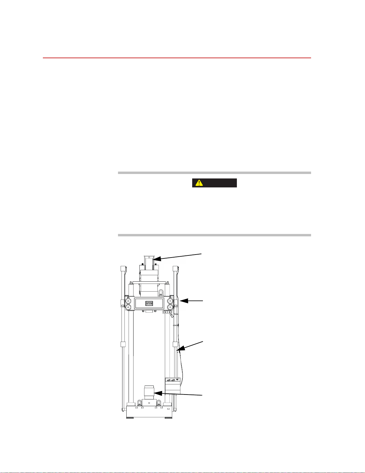
Preventing Rust
WARNING
Unpainted surfaces: Spray with silicone, and
then wipe with a clean, lint-free cloth. Or,
wipe with a clean, lint-free cloth dampened
with clean hydraulic fluid.
Chrome plated surfaces: For microscratches,
wipe with a clean, lint-free cloth dampened
with #1 kerosene. For rust discoloration,
polish with a very fine emery cloth, and then
wipe down.
Black oxide surfaces: Spray with silicone, and
then wipe with a clean, lint-free cloth. Or, wipe
with a clean, lint-free cloth dampened with
clean hydraulic fluid.
Painted surfaces: For small scratches, use
touchup paint. For large scratches, sand,
prime, and use touchup paint.
Preventing Rust
Where you operate the load frame determines how often you take rust prevention
measures. Humid and corrosive environments require more prevention.
Recommended
supplies:
• 1 grade kerosene
• Silicone spray
• 000 emery cloth
• Touchup paint; MTS part numbers 011-059-854 (beige),
011-059-856 (grey), 044-587-501 (brown)
• Metal primer paint
• Lint-free cloths
The crosshead can slip if the columns are still damp with kerosene.
You can be hurt and your equipment damaged.
The crosshead locks cannot securely clamp on damp columns. Wait until the
columns are dry to the touch before moving and locking the crosshead.
54
Maintenance
Series 311 Load Frame

Checking the Accumulators’ Precharge
Checking the Accumulators’ Precharge
An accumulators’ correct precharge pressure is written on its label. Begin by
checking precharge pressures at least once a month.
See the Series 111 Accumulator Product Information manual for the complete
details on checking the precharge intervals and servicing the accumulators.
Record both the pressures and the room temperature in a log book. Use these
readings as a basis for increasing or decreasing the interval between pressure
checks.
Generally, recharging is required when there is a change of ±1.4 MPa
(200 psi) in the pressure line accumulator or ±50% in the return line accumulator.
Series 311 Load Frame Maintenance
55

Bleeding the Hydraulic Lift Cylinders
Bleed Ports can
be located at
either end of the
cylinder
Bleeding the Hydraulic Lift Cylinders
Bleed both hydraulic lift cylinders whenever the crosshead does not move
smoothly. Also bleed them whenever the sealed side of the hydraulic system has
been opened to air.
56
Maintenance
Location of the Bleed Ports
Series 311 Load Frame

Bleeding the Hydraulic Lift Cylinders
CAUTION
WARNING
The crosshead can slowly drift down the columns if the locks are turned off
and the hydraulic pressure is turned off.
The crosshead can damage any test fixtures, grips, and specimen in its
path.
Unlock the crosshead only to reposition it. Always lock the crosshead after you
have repositioned it, and never leave the crosshead unlocked.
1. Ensure the crosshead is locked.
2. Turn on system electrical power.
3. Reset any active interlocks at the test controller.
4. Turn on high hydraulic pressure.
5. If there is a specimen in the load frame, remove it.
The lifts contain hydraulic fluid under high pressure.
If the bleed port screw is unscrewed all the way, the screw can fly out of its
port at high velocity and it could hurt you or damage your equipment.
Unscrew the bleed port screw no more than 1/2 turn to vent the trapped air.
Open to Bleed
6. Use a 1/8 inch hex key (or slotted screwdriver, depending on model number)
to open one of the bleed ports.
Do not unscrew the bleed port screw more than 1/2 turn.
Series 311 Load Frame Maintenance
57

Bleeding the Hydraulic Lift Cylinders
7. Briefly turn the lift control to lift the crosshead position so the lift cylinders
8. Shut the bleed port when bubble-free fluid begins oozing out. If necessary,
9. Repeat Step 6 through Step 8 to bleed the air out of the other lift cylinder.
pressurize. Then return it to the stop crosshead position.
Close When Bubble-Free
again pressurize the lift cylinders to force all the air out.
Note If fluid continues to leak out of a shut bleed port, turn off hydraulic
pressure to the load frame. Let the pressure in the lift cylinders return to
zero. Then replace both bleed port screws (MTS part number
010-037-601).
10. Turn on high hydraulic pressure. If pressure was reduced at the hydraulic
power unit, restore full pressure.
11. Briefly tu rn th e Lift Control to the lift crosshead position to pressurize the
lift cylinders. Then return it to the stop crosshead position.
12. Unlock the crosshead and exercise the crosshead. Then return to the stop
crosshead position. Raise and lower the crosshead to check for smooth
operation. Lock the crosshead.
13. If the crosshead does not move smoothly, go back to Step 4 and continue
from there.
58
Maintenance
Series 311 Load Frame

Adjusting the Hydraulic Locks
CAUTION
Hydraulic locks will need adjustment if the crosshead does not move smoothly
after bleeding the lift cylinders. Adjustment might also be needed if the
crosshead slips under full load. If adjusting the hydraulic locks does not fix these
problems, contact MTS Systems Corporation.
1. Turn on electrical power at the controller. Do not turn on hydraulic pressure
yet.
2. If the crosshead is already at a comfortable working level with no specimen
installed, proceed to the next step.
If not, position the crosshead for a comfortable working level. Proceed as
follows:
A. Turn on high hydraulic pressure.
B. If there is a specimen in the load frame, remove it.
C. Unclamp the crosshead.
Adjusting the Hydraulic Locks
D. Move the crosshead to a comfortable working height.
E. Clamp the crosshead.
F. Turn off hydraulic pressure.
The crosshead can slowly drift down the columns if the locks are turned off
and the hydraulic pressure is turned off.
The crosshead can damage any test fixtures, grips, and specimen in its
path.
Unlock the crosshead only to reposition it. Always lock the crosshead after you
have repositioned it, and never leave the crosshead unlocked.
3. Install the shipping collars on diagonally opposite columns directly above
and below the crosshead. See “Shipping Collar Torque Specifications” on
page 35.
4. Use the Crosshead Lift/Lock Controls to the unclamp the crosshead to
remove pressure from the hydraulic locks. Wait two minutes for the pressure
in the locks to drop to zero before going on to the next step.
5. Use a spanner wrench to tighten the clamping piston onto the tie rod until all
slack is removed and the clamping piston bottoms into the cylinder.
6. Loosen the clamping piston 1/8 turn.
7. Repeat Step 5 and Step 6 for the remaining hydraulic locks.
8. Turn on electrical power at the test controller if you have not already done
so and reset any active interlocks at the test controller.
Series 311 Load Frame Maintenance
59

Adjusting the Hydraulic Locks
9. Turn on high hydraulic pressure.
10. Use the Crosshead Lift/Lock Controls to the clamp the crosshead in
position to pressurize the hydraulic locks.
11. Remove and reinstall the shipping collars for load frame operation. See
“Removing the Shipping Collars” on page 40.
60
Maintenance
Series 311 Load Frame

Aligning the Force Transducer
WARNING
This section describes how to align a force transducer with the load frame
actuator.
Alignment takes place in a crush zone with hydraulic pressure on.
Hands can be crushed and equipment can be damaged equipment when
hydraulics are turned on. Be careful when working in a crush zone.
To reduce the hazards in this procedure:
• Ensure that you set and enable displacement interlocks to limit the
actuator’s movement.
• Ensure that the crosshead is locked.
• Reduce the load frame’s hydraulic pressure to low.
Aligning the Force Transducer
• Keep your hands out of the crush zone except when performing the
steps needed to complete this procedure.
Required equipment • Torque wrench with a 5 to 135 N•m (5 to 100 lbf•ft) range
• Molykote G·n paste
• Rubber mallet
• 0.0025 mm (0.0001 in) precision dial indicator with a magnetic base
Procedure 1. Set up the load frame.
A. If grips are installed, remove them.
B. Loosen the clamp rings (two rings are usually located on diagonally
opposite columns) and slide them down the column.
C. Turn on system electrical power.
D. Turn on high hydraulic pressure.
E. Position the actuator at midstroke.
F. Set and enable the test controller’s upper and lower limit detect
interlocks to limit the actuator’s movement to 2 mm (0.10 in) in each
direction.
G. Unclamp the crosshead and reposition it so there is about 450 mm (18
in) between the top of the actuator and the bottom of the force
transducer.
H. Clamp the crosshead to lock it in place.
I. Set the clamp rings below the crosshead and tighten them to the
columns.
Series 311 Load Frame Maintenance
61
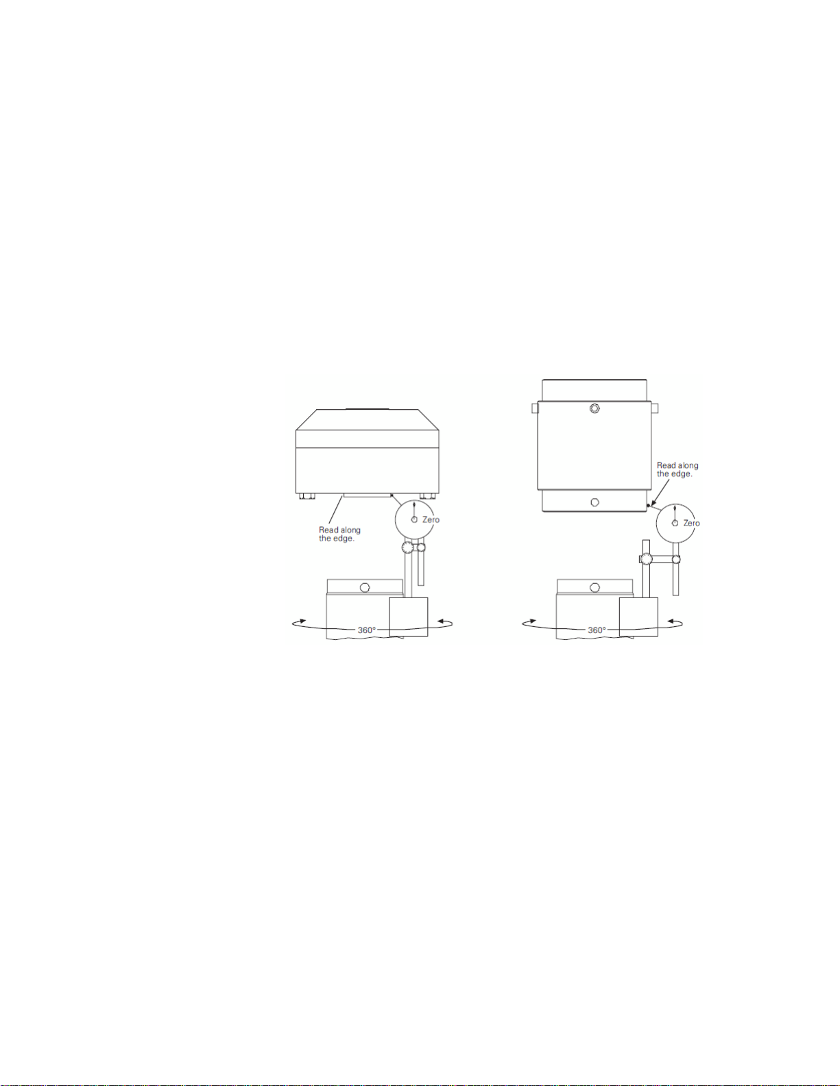
Aligning the Force Transducer
J. If your load frame has an anti-rotate actuator, unscrew the four cap
screws that attach the anti-rotate plate to the bottom of the piston. The
anti-rotate plate is at one end of the actuator.
2. Check the alignment.
Check the alignment between the force transducer and the actuator.
A. Attach the dial indicator to the actuator.
On a low profile force transducer, adjust the indicator to take the
reading along the edge of the loading surface.
On cylindrical style force transducers, adjust the indicator so that its
stylus just touches the polished bottom edge of the transducer.
B. Zero the indicator.
62
Maintenance
Attaching and Zeroing the Indicator
Series 311 Load Frame

Aligning the Force Transducer
C. Slowly turn the actuator to rotate the indicator 360° around the force
transducer.
Stop frequently to take indicator readings. Keep your hands off the
actuator and indicator when taking the readings. Compute the total
indicator runout (TIR). Take the maximum dial indicator reading and
subtract the minimum dial indicator reading.
TIR Tolerance
Model TIR
311.11 0.0381 mm (0.0015 in)
311.21 0.0508 mm (0.002 in)
311.31 0.0762 mm (0.003 in)
311.41 0.1016 mm (0.004 in)
311.51 0.1016 mm (0.004 in)
311.61 0.1016 mm (0.004 in)
311.71 0.1016 mm (0.004 in)
D. If the TIR is within the tolerance (as listed in the table “TIR Tolerance”
on page 63), the force transducer is accurately aligned with the
actuator. Go to Step 5.
If the TIR is greater than the tolerance, the force transducer needs to be
aligned with the actuator. Start over with Step 2.
3. Prepare the force transducer.
Loosen the jackbolts or setscrews in 1/4 turn steps to remove most of the
tension on the force transducer. Remove and lubricate each bolt one at a
time.
4. Align the force transducer.
This step describes how to align a force transducer to the crosshead.
A. Lightly tap the transducer wi th the rubber mall et to change its position
until you get a TIR of 0.038 mm (0.0015 in) or less.
Series 311 Load Frame Maintenance
63

Aligning the Force Transducer
B. Tighten to 5% of the torque recorded on the identification plate using
the appropriate bolt torque sequence.
Bolt Torque Sequence
C. Rotate the indicator to see if the TIR is still 0.038 mm (0.0015 in) or
less. If not, loosen the nut or preloader collar and return to Step 3.
(Loosen the preloader collar following the sequence shown below.)
D. Repeat Steps B and C to tighten the force transducer for the fol lowing
torque progression: 50%, 75%, and 100%.
64
Maintenance
Series 311 Load Frame

load cell
Aligning the Force Transducer
Cap Screw Torque Specifications
*
Cap Screw Size Torque
†
311.11
‡
311.11
311.21) 1-8 UNC-2A
311.31 1-8 UNC-2A
§
311.41
#
311.41
311.51 1-1/2-6 UNC-2A
* Cap screw specifications for the Model 311.61 and 311.71 Load Frames
are contained on the drawings and parts lists for the specific unit.
† with a 100 kN (22 kip) force transducer
‡ with a 250 kN (55 kip) force transducer
§ with a 1500 kN (330 kip) force transducer
# with a 2500 kN (550 kip) force transducer
5/8-11
5/8-11
1-1/2-6
1-1/2-6
70 N
•m (52 lb•ft)
176 N
•m (130 lb•ft)
570 N•m (420 lb•ft)
635 N•m (470 lb•ft)
1220 N
•m (900 lb•ft)
1760 N•m (1300 lb•ft)
1490 N•m (1100 lb•ft)
5. Finish the procedure.
In this step, you complete the force transducer alignment procedure.
A. Remove the dial indicator.
B. If you reduced pressure at the hydraulic power unit, restore full
hydraulic pressure.
C. Turn the load frame’s hydraulic pressure to off.
Series 311 Load Frame Maintenance
65

Aligning the Force Transducer
66
Maintenance
Series 311 Load Frame

Servohydraulic Load Frame Maintenance and Service Logs
Contents 8 Hours/Daily 68
40 Hours/Weekly 69
80 Hours/Biweekly 70
500 Hours: Crosshead and Frame 71
500 Hours: Actuator 72
500 Hours: HSM 73
500 Hours: Hoses and Cables 74
500 Hours: Overall Complete System 75
500 Hours: Grips 76
1000 Hours 77
2000 Hours: Annual Maintenance 78
Servohydraulic Load Frame Maintenance and Service Logs
67

8 Hours/Daily
8 Hours/Daily
8 Hours/Daily Service Interval Recommendation
Check Actuator
Platen Area to be
Clean
Date Performed by Performed by Performed by Notes
Monitor Filter
Indicators
Check Hazard
Labels for
Legibility
68
Servohydraulic Load Frame Maintenance and Service Logs

40 Hours/Weekly
40 Hours/Weekly
40 Hours/Weekly Service Interval Recomme ndation
Check Hoses/
Cables/
Connectors
Date Performed by Performed by Performed by Performed by Performed by Performed by Notes
Check
Crosshead/
Lifts/Supports
Check Actuator
Area to Be Dry
Check
Hydraulic
Service
Manifold
Check Lift Seal
Condition to be
Dry
Check Lock
Seal Condition
to be Dry
Servohydraulic Load Frame Maintenance and Service Logs
69

80 Hours/Biweekly
80 Hours/Biweekly
80 Hours/Biweekly Service Interval Recommendation
Bionix Lubricate
Axial/Torsional
Spline (75-100 hrs)
Date Performed by Performed by Notes
Check Actuator
70
Servohydraulic Load Frame Maintenance and Service Logs

500 Hours: Crosshead and Frame
500 Hours Service Interval Recommendation
500 Hours: Crosshead and Frame
Check
Crosshead/
Lifts/
Supports
Date Performed by Performed by Performed by Performed by Performed by Notes
Crosshead
Speed is
Appropriate
Lift Seal
Condition is
Dry
Crosshead
Unlock Causes
Program
Interlock
Lock Seal
Condition is
Dry
500 Hours Service Interval Recommendation
Load Frame
Support/
Airbags/Pads
Crosshead
Columns are
Clean
Crosshead
Movement is
Smooth
Column
Abrasions are
Acceptable
Date Performed by Performed by Performed by Performed by Notes
Servohydraulic Load Frame Maintenance and Service Logs
71

500 Hours: Actuator
500 Hours: Actuator
500 Hours Service Interval Recommendation
Cursory Check
of Actuator
Date Performed by Performed by Performed by Notes
Bionix Lubricate
Axial/Torsional
Spline
(75-100 hrs)
Actuator Area is
Dry
500 Hours Service Interval Recommendation
Piston Rod Wear
is Acceptable
Actuator Platen
Area is Clean
Date Performed by Performed by Notes
72
Servohydraulic Load Frame Maintenance and Service Logs

500 Hours: HSM
500 Hours: HSM
500 Hours Service Interval Recommendation
Cursory Check
of Hydraulic
Service
Manifold
Date Performed by Performed by Performed by Performed by Notes
Accumulator
Connections are
Tight
Monitor Filter
Indicators
Accumulator
Caps/Guards
are Present
Manifold Hose
Connections
are Tight
500 Hours Service Interval Recommendation
Oil on the Gas
Side of the
Piston
Accumulator
Connections are
Dry
Check and
Adjust Pressure
in Accumulator
Date Performed by Performed by Performed by Performed by Notes
Servohydraulic Load Frame Maintenance and Service Logs
73

500 Hours: Hoses and Cables
500 Hours: Hoses and Cables
500 Hours Service Interval Recommendation
Cursory Check
of Hoses/
Cables/
Connectors
Date Performed by Performed by Performed by Performed by Performed by Notes
Absence of
Hose
Abrasions,
Blisters,
Vulcanizing
Cable
Condition and
Routing is
Acceptable
Check
Transducer
Connections
Hose
Connections
and Crimps are
Dry
74
Servohydraulic Load Frame Maintenance and Service Logs

500 Hours: Overall Complete System
500 Hours Service Interval Recommendation
500 Hours: Overall Complete System
Overall
System
Condition is
Acceptable to
Use
Date Performed by Performed by Performed by Performed by Notes
Valve Balance
check
displacement
control
Tuning
Parameters are
Appropriate/
System Stable
Valve Dither
Response
E-Stop is
Working if
Applicable
500 Hours Service Interval Recommendation
Response to
Full Stroke
Waveform,
Visual and
Audible
Date Performed by Performed by Notes
Servohydraulic Load Frame Maintenance and Service Logs
75

500 Hours: Grips
500 Hours: Grips
500 Hours Service Interval Recommendation
Cursory Check
of Grips/Grip
Control
Date Performed by Performed by Performed by Performed by Performed by Notes
Grip Supply
Connections
are Dry
Grip Seals are
Dry
Grip Action is
Acceptable
Lubricate Grip
Inserts
76
Servohydraulic Load Frame Maintenance and Service Logs

1000 Hours
1000 Hours
1000 Hours Service Interval Recommendation
All 500 hr
Maintenance
Procedures
Date Performed by Performed by Performed by Notes
Hydraulic
Crosshead Locks
are Functioning
Properly
Bleed
Crosshead Lift
Cylinders
Servohydraulic Load Frame Maintenance and Service Logs
77

2000 Hours: Annual Maintenance
2000 Hours: Annual Maintenance
2000 Hours Service Interval Recommendation
All 1000 hr
Maintenance
Procedures
Date Performed by Performed by Performed by Performed by Notes
Lubricate
Manual
Crosshead
Lock Bolts
Change
Hydraulic
Service
Manifold Filters
Low Pressure
Adjustment
(Model 294
HSM)
78
Servohydraulic Load Frame Maintenance and Service Logs

Addendum
This addendum provides information on options not documented in the original
load frame manual.
Actuator velocity limiting switch
This switch/indicator is used to control actuator speed. The switch is spring
loaded left/right with a center neutral position. Momentarily turn the switch right
to the [ ] and then return the switch to the center position for high-speed,
normal testing operation. The switch indicator will light, indicating the actuator
rod is capable of high-speed, normal testing operation. Momentarily turn the
switch left to the [ ] and then return the switch to the center position for lowspeed, specimen installation and removal. The switch indicator will extinguish,
indicating the actuator rod is in a low speed condition for specimen installation.
Control Panel (Custom)
The Emergency Stop button is standard; the other controls are optional.
Crosshead lifts control Controls the crosshead lifts to raise and lower the crosshead hydraulically.
Crosshead locks control Controls the crosshead locks to lock and unlock the crosshead hydraulically.
Actuator velocity limiting
switch
Emergency Stop Removes hydraulic pressure from the load unit and issues an interlock signal to
Handset The handset has an encoder and buttons to help you during specimen installation
Specimen Installation
Prerequisite You must have the necessary grips and/or fixturing installed. You must also have
Controls actuator rod speed. There are two positions: one for reduced speed of
the actuator rod for specimen installation and one for normal, high-speed testing
operaton.
the controller to stop the test program.
and test execution. The handset also has an alphanumeric display and LEDs to
provide feedback.
The procedure to install a specimen varies due to the variety of test fixtures,
grips, and the type of specimen being installed. This section should be considered
a guideline. You need to modify this procedure to suit your equipment.
the controller set up to control the actuator movement, and you must have a test
program defined.
Load Unit Addendum Addendum
79

When changing hydraulic grips, make sure you cap or plug the hydraulic
CAUTION
WARNING
hoses when removed to prevent oil spillage.
Oil spillage can create an environmental concern and slippery surface that
can cause personal injury.
Promptly clean up any oil that might have spilled when hoses were removed.
The crosshead is very heavy.
A dropping crosshead can crush hands, damage grips, and smash
specimens.
Be careful when working in a crush zone. T o reduce the hazards in this procedure,
observe the following:
Set and enable displacement interlocks to limit the actuator’s movement.
Ensure that the crosshead is locked.
Ensure that the columns are clean and dry.
Keep your hands out of the crush zone except when performing the steps needed
to complete this procedure.
1. Prepare the components for specimen installation.
A. Ensure that the crosshead is locked.
B. Turn on system electrical power.
C. Apply HPU system high hydraulic pressure. Apply load unit station
low hydraulic pressure.
D. If the system has a 494 based controller, enable the Gate Interlock.
E. Set the actuator velocity limiting switch to (restricted flow).
F. Enable the handset and use the thumbwheel to move the actuator to its
start position (usually mid-displacement). The starting position of the
actuator depends on the type of fixtures, grips, and the test being set up.
80
Addendum
Load Unit Addendum

For load units with hydraulic lifts and locks, the crosshead can slowly drift
CAUTION
CAUTION
down the columns if the locks are turned off and when hydraulic pressure is
turned off.
The crosshead can damage any test fixtures, grips, and specimen in its
path.
Unlock the crosshead only to reposition it. Always lock the crosshead after you
have repositioned it, and never leave the crosshead unlocked.
2. Set the crosshead position.
The crosshead position depends on the length of the specimen being tested,
the starting position of the actuator, and the size of the fixtures or grips
being used.
3. Install the specimen.
Specimen installation varies according to the type of grip being used. See
the appropriate grip manual for installation instructions. Each type of grip
requires the specimen or specimen fixture to fit properly into the grip. You
should always review specimen installation procedures found in any grip
product information manual.
Handset Control
Before testing, ensure both grips are clamped and the specimen is secure.
An insufficiently gripped specimen can cause specimen damage, equipment
damage, and the possibility of specimen fragmentation.
4. Set up the load frame for testing.
A. Set the actuator velocity limiting switch to (full flow).
B. Disable the handset and set up the controller for system operation.
5. Reset the controller interlock.
6. Apply load unit station high hydraulic pressure.
The handset has an encoder and buttons to help you during specimen installation
and test execution. The handset also has an alphanumeric display and LEDs to
provide feedback.
Load Unit Addendum Addendum
81
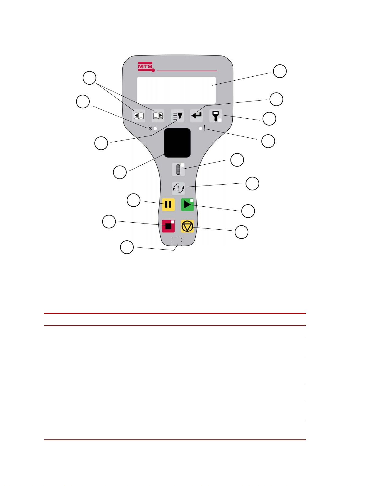
Handset functions The handset is intended to be used in a system for specimen loading or setup. In
1
2
3
4
5
6
7
15
14
12
11
10
9
8
LINE 1 UP TO 20 CHAR
LINE 2 UP TO 20 CHAR
LINE 3 UP TO 20 CHAR
LINE 4 UP TO 20 CHAR
13
# Control/Indicator Description
some applications, it can be used to completely run a test.
Handset Controls and Indicators
1Page
2Active
Displays previous or next text in the display.
Indicator. When lit, indicates the system is active (power
applied).
3 Scroll highlight
4 Thumb-wheel
5Pause
6Stop
Scrolls the highlighted selection down. Selection cycles to the
top when the bottom line is highlighted and the switch is
pressed.
Makes fine actuator adjustment (towards display – up; away
from display – down). Only if Handset Enable is active.
Pauses the test action. This must be pressed again for the test to
resume. Only if the application test software is active.
Stops the test action. Only if the application test software is
active.
82
Addendum
Load Unit Addendum

Handset Controls and Indicators
# Control/Indicator Description
7 Connector
8 Hydraulic off
9Start
10 Interlock reset
11 Thumbwheel enable
12 Fault
13 Handset enable
14 Select (En t er)
15 Display
Test System Modes of Operation
There are four operating modes for this test system:
RJ-45, to Controller.
Shuts down the HPU.
Starts the test action. Only if the application test software is
active.
Resets active interlock(s) providing the cause for the
interlock(s) has been remedied.
Press to enable the thumbwheel to position the actuator. Press
again to disable the thumbwheel, Indicator lights when
thumbwheel is active.
Indicator. When lit, indicates an active fault or interlock.
Used to enable/disable the handset. When the indicator is lit,
the handset is enabled for control of the actuator.
Selects the highlighted line in the display.
Four lines, 20 characters per line.
• Hydraulic Power Off
• Specimen Installation and Setup
• Run mode
• Service
Hydraulic power off Hydraulic Power is prevented from energizing the circuit via the hydraulic
service manifold. Full access to the test area is allowed in this mode.
Specimen installation
and setup
The controller provides a means for creating a specimen installation mode. This
mode typically uses the Channel Limited Channel (CLC) control method. The
primary control channel is Displacement (stroke) with maximum limits set on
applied force. Tuning parameters unique to this mode optimize manual contro l
during this mode. In addition, a maximum velocity command is set.
The handset has the ability to have a configuration specific desired response to
the thumbwheel encoder on the handset for a precise level of control.
In conjunction with the controller and specimen installation mode using the
handset, the load frame itself has two operation modes, full flow, and actuator
velocity limiting restricted flow. A switch on the load frame control panel
activates a solenoid which controls a hydraulic circuit within the load frame
hydraulic service manifold. In the actuator velocity limiting mode, oil flow to the
actuator is directed through an orifice which limits actuator velocity to 10 mm/
second or less.
Load Unit Addendum Addendum
83

During normal setup operation, the operator would follow this sequence:
1. Switch the system to the CLC manual control mode.
2. Activate the handset control.
3. Switch to velocity limiting mode on the load frame control panel.
4. Specimen setup or removal could then take place.
To resume to normal test mode , the operator would reverse the sequence:
1. Switch to full flow mode.
2. Deselect handset control.
3. Put the system into the control mode desired for the start of the test.
Run mode The system is fully operational when all of the following have been satisfied.
• Actuator velocity limiting is in full-flow state.
• The handset and manual control are yielded to the controller.
• The system is in high pressure.
Service Most normal service requirements can be met utilizing the normal three operating
modes as listed previously. However , there can be circumstances where operation
in full flow mode with the Test Area Enclosure open is required. In these cases,
trained service personnel can disconnect the standard enclosure cable, and
temporarily replace it with a service connector. This operation is not considered
typical use, and should only be used by trained individuals.
Optional interlock
logic
In addition to the actuator velocity limiting switch, some systems can include
interlock switches on a Test Area Guard or interlock switch(es) on environmental
products (such as a door interlock switch on an environmental chamber). Refer to
the wiring assembly harness in the Load Unit/Load Frame section and the wiring
diagram for other interlock switches for specific information.
84
Addendum
Load Unit Addendum


m
MTS Systems Corporation
14000 Technology Drive
Eden Prairie, Minnesota 55344-2290 USA
Toll Free Phone: 800-328-2255
(within the U.S. or Canada)
Phone: 952-937-4000
(outside the U.S. or Canada)
Fax: 952-937-4515
E-mail: info@mts.com
http://www.mts.com
ISO 9001 Certified QMS
 Loading...