


 Loading...
m
be certain.
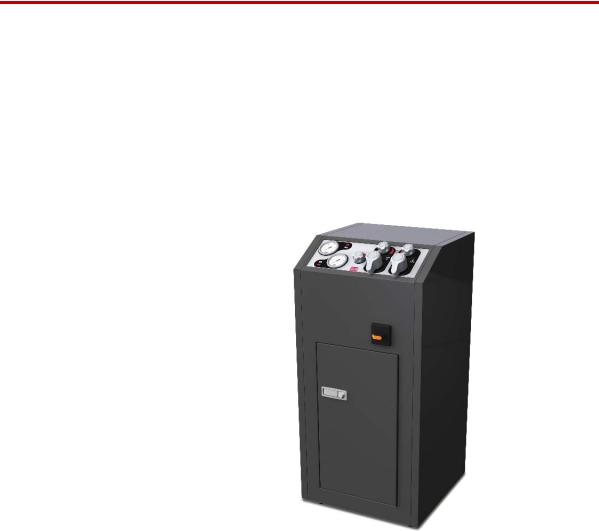
Series 685 Hydraulic Grip Supply
Product Information
Model 685.10
Model 685.22
Model 685.60
100-241-254 A
Copyright information Trademark information
© 2011 MTS Systems Corporation. All rights reserved.
MTS is a registered trademark of MTS Systems Corporation within the United States. This trademark may be protected in other countries.
Mobil 525 SHC is a registered trademark of Mobil Corporation.
Publication information |
Manual Part Number |
Publication Date |
|
|
|
|
100-241-254 A |
August 2011 |
|
|
|
2 |
Contents |

Contents
Technical Support |
5 |
|
|
|
|
||
|
|
|
|
|
|||
|
How to Get Technical Support |
5 |
|
|
|||
|
Before You Contact MTS |
5 |
|
|
|
||
|
If You Contact MTS by Phone |
6 |
|
|
|||
|
Problem Submittal Form in MTS Manuals 7 |
|
|||||
Preface |
9 |
|
|
|
|
|
|
|
|
|
|
|
|
|
|
|
Before You Begin |
9 |
|
|
|
|
|
|
Conventions 10 |
|
|
|
|
|
|
|
Documentation Conventions |
10 |
|
|
|||
Introduction |
13 |
|
|
|
|
|
|
|
|
||||||
|
Series 685 Grip Supply Component Identification 14 |
||||||
|
Series 685 Grip Supply Functional Description |
15 |
|||||
|
Series 685 Grip Supply Hydraulic Schematics |
16 |
|||||
|
Series 685 Grip Supply Specifications |
18 |
|
||||
Safety |
19 |
|
|
|
|
|
|
|
|
|
|
|
|
||
|
General Safety Practices |
19 |
|
|
|
||
|
Hazard Placard Placement |
23 |
|
|
|||
|
Power Loss Considerations 26 |
|
|
||||
Installation |
27 |
|
|
|
|
|
|
|
|
|
|
||||
|
Lifting and Moving the Grip Supply |
27 |
|
||||
|
Series 685 Grip Supply Installation Procedure |
29 |
|||||
Series 685 Grip Supply Product Information |
Contents |
3 |

Operation 33
Series 685 Grip Supply Controls and Indicators |
33 |
|||
Determining the Grip Operating Pressure |
35 |
|
||
How to Adjusting the Output Pressure |
35 |
|
|
|
About Rate Control 36 |
|
|
|
|
How to Grip a Specimen |
37 |
|
|
|
How to Remove a Specimen from Grips |
38 |
|
||
How to Recover from a Thermal Overload |
39 |
|
||
Maintenance 41 |
|
|
|
|
|
|
|||
Series 685 Grip Supply Maintenance Intervals |
41 |
|||
Hydraulic Fluid Maintenance 42 |
|
|
|
|
Remove the Series 685 Grip Supply Side Panels |
43 |
|||
Clean the Heat Exchanger |
43 |
|
|
|
Replace the Hydraulic Fluid Filter Element |
43 |
|
||
Grip Supply Transport or Storage Preparation 44
4 |
Contents |
Series 685 Grip Supply Product Information |

How to Get Technical Support
Technical Support
How to Get Technical Support
Start with your manuals
Technical support methods
MTS web site
www.mts.com
Telephone
Fax
The manuals supplied by MTS provide most of the information you need to use and maintain your equipment. If your equipment includes MTS software, look for online help and README files that contain additional product information.
If you cannot find answers to your technical questions from these sources, you can use the internet, e-mail, telephone, or fax to contact MTS for assistance.
MTS provides a full range of support services after your system is installed. If you have any questions about a system or product, contact MTS in one of the following ways.
The MTS web site gives you access to our technical support staff by means of a Technical Support link:
www.mts.com > Contact Us > Service & Technical Support
tech.support@mts.com
MTS Call Center 800-328-2255
Weekdays 7:00 A.M. to 5:00 P.M., Central Time
952-937-4515
Please include “Technical Support” in the subject line.
Before You Contact MTS
Know your site number and system number
MTS can help you more efficiently if you have the following information available when you contact us for support.
The site number contains your company number and identifies your equipment type (material testing, simulation, and so forth). The number is usually written on a label on your MTS equipment before the system leaves MTS. If you do not have or do not know your MTS site number, contact your MTS sales engineer.
Example site number: 571167
When you have more than one MTS system, the system job number identifies which system you are calling about. You can find your job number in the papers sent to you when you ordered your system.
Example system number: US1.42460
Series 685 Grip Supply Product Information |
Technical Support |
5 |
If You Contact MTS by Phone
Know information from If you have contacted MTS about this problem before, we can recall your file. prior technical You will need to tell us the:
assistance
•MTS notification number
•Name of the person who helped you
Identify the problem Describe the problem you are experiencing and know the answers to the following questions:
•How long and how often has the problem been occurring?
•Can you reproduce the problem?
•Were any hardware or software changes made to the system before the problem started?
Know relevant computer information
•What are the model numbers of the suspect equipment?
•What model controller are you using (if applicable)?
•What test configuration are you using?
If you are experiencing a computer problem, have the following information available:
•Manufacturer’s name and model number
Know relevant software information
•Operating software type and service patch information
•Amount of system memory
•Amount of free space on the hard drive in which the application resides
•Current status of hard-drive fragmentation
•Connection status to a corporate network
For software application problems, have the following information available:
•The software application’s name, version number, build number, and if available, software patch number. This information is displayed briefly when you launch the application, and can typically be found in the “About” selection in the “Help” menu.
•It is also helpful if the names of other non-MTS applications that are running on your computer, such as anti-virus software, screen savers, keyboard enhancers, print spoolers, and so forth are known and available.
If You Contact MTS by Phone
Your call will be registered by a Call Center agent if you are calling within the United States or Canada. Before connecting you with a technical support specialist, the agent will ask you for your site number, name, company, company address, and the phone number where you can normally be reached.
6 |
Technical Support |
Series 685 Grip Supply Product Information |
Problem Submittal Form in MTS Manuals
Identify system type
Be prepared to troubleshoot
Write down relevant information
After you call
If you are calling about an issue that has already been assigned a notification number, please provide that number. You will be assigned a unique notification number about any new issue.
To assist the Call Center agent with connecting you to the most qualified technical support specialist available, identify your system as one of the following types:
•Electromechanical materials test system
•Hydromechanical materials test system
•Vehicle test system
•Vehicle component test system
•Aero test system
Prepare yourself for troubleshooting while on the phone:
•Call from a telephone when you are close to the system so that you can try implementing suggestions made over the phone.
•Have the original operating and application software media available.
•If you are not familiar with all aspects of the equipment operation, have an experienced user nearby to assist you.
Prepare yourself in case we need to call you back:
•Remember to ask for the notification number.
•Record the name of the person who helped you.
•Write down any specific instructions to be followed, such as data recording or performance monitoring.
MTS logs and tracks all calls to ensure that you receive assistance and that action is taken regarding your problem or request. If you have questions about the status of your problem or have additional information to report, please contact MTS again and provide your original notification number.
Problem Submittal Form in MTS Manuals
Use the Problem Submittal Form to communicate problems you are experiencing with your MTS software, hardware, manuals, or service which have not been resolved to your satisfaction through the technical support process. This form includes check boxes that allow you to indicate the urgency of your problem and your expectation of an acceptable response time. We guarantee a timely response—your feedback is important to us.
The Problem Submittal Form can be accessed:
•In the back of many MTS manuals (postage paid form to be mailed to MTS)
•www.mts.com > Contact Us > Problem Submittal Form (electronic form to be e-mailed to MTS)
Series 685 Grip Supply Product Information |
Technical Support |
7 |
Problem Submittal Form in MTS Manuals
8 |
Technical Support |
Series 685 Grip Supply Product Information |

Before You Begin
Preface
Before You Begin
Safety first!
Other MTS manuals
Before you attempt to use your MTS product or system, read and understand the Safety manual and any other safety information provided with your system. Improper installation, operation, or maintenance of MTS equipment in your test facility can result in hazardous conditions that can cause severe personal injury or death and damage to your equipment and specimen. Again, read and understand the safety information provided with your system before you continue. It is very important that you remain aware of hazards that apply to your system.
In addition to this manual, you may receive additional MTS manuals in paper or electronic form.
If you have purchased a test system, it may include an MTS System Documentation CD. This CD contains an electronic copy of the MTS manuals that pertain to your test system, including hydraulic and mechanical component manuals, assembly drawings and parts lists, and operation and preventive maintenance manuals. Controller and application software manuals are typically included on the software CD distribution disc(s).
Series 685 Grip Supply Product Information |
Preface |
9 |

Conventions
Conventions
Documentation Conventions
Hazard conventions
Notes
Special terms
Illustrations
Electronic manual conventions
The following paragraphs describe some of the conventions that are used in your MTS manuals.
As necessary, hazard notices may be embedded in this manual. These notices contain safety information that is specific to the task to be performed. Hazard notices immediately precede the step or procedure that may lead to an associated hazard. Read all hazard notices carefully and follow the directions that are given. Three different levels of hazard notices may appear in your manuals. Following are examples of all three levels.
Note For general safety information, see the safety information provided with your system.

 DANGER
Danger notices indicate the presence of a hazard with a high level of risk which, if ignored, will result in death, severe personal injury, or substantial property damage.

 WARNING
Warning notices indicate the presence of a hazard with a medium level of risk which, if ignored, can result in death, severe personal injury, or substantial property damage.

 CAUTION
Caution notices indicate the presence of a hazard with a low level of risk which, if ignored, could cause moderate or minor personal injury, equipment damage, or endanger test integrity.
Notes provide additional information about operating your system or highlight easily overlooked items. For example:
Note Resources that are put back on the hardware lists show up at the end of the list.
The first occurrence of special terms is shown in italics.
Illustrations appear in this manual to clarify text. It is important for you to be aware that these illustrations are examples only and do not necessarily represent your actual system configuration, test application, or software.
This manual is available as an electronic document in the Portable Document File (PDF) format. It can be viewed on any computer that has Adobe Acrobat Reader installed.
10 |
Preface |
Series 685 Grip Supply Product Information |
Documentation Conventions
Hypertext links The electronic document has many hypertext links displayed in a blue font. All blue words in the body text, along with all contents entries and index page numbers, are hypertext links. When you click a hypertext link, the application jumps to the corresponding topic.
Series 685 Grip Supply Product Information |
Preface |
11 |
Documentation Conventions
12 |
Preface |
Series 685 Grip Supply Product Information |
Introduction
Contents
What you need to know
EU Declarations
The MTS Series 685 Hydraulic Grip Supplies provide an easy way to grip specimens for testing. The grip supplies are available with a variety of hydraulic output pressures. Some include self-contained hydraulic systems.
Series 685 |
Grip Supply Component Identification 14 |
|
Series 685 |
Grip Supply Functional Description |
15 |
Series 685 |
Grip Supply Hydraulic Schematics |
16 |
Series 685 |
Grip Supply Specifications 18 |
|
MTS Systems Corporation assumes that you know how to use your controller. See the appropriate manual for information about performing any controllerrelated step in this manual’s procedures. You are expected to know how to perform the following procedures:
•Turn hydraulic pressure on and off.
•Select a control mode.
•Manually adjust the actuator position.
•Install a specimen.
•Define a simple test.
•Run a test.
If applicable, a Declaration of Incorporation is supplied with the machinery; an example of the Declaration of Incorporation is provided at the end of this manual.
Series 685 Grip Supply Product Information |
Introduction |
13 |
Series 685 Grip Supply Component Identification
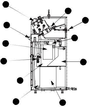
Series 685 Grip Supply Component Identification
Use the following figure to identify the components referenced in this manual.
1 |
Right Side |
|
11 |
2 |
10 |
|
|
3 |
9 |
|
|
4 |
8 |
|
5 |
6 |
7 |
|
Component Identification |
|
|
ITEM |
COMPONENT |
|
|
1 |
Control Manifold |
|
|
2 |
Power Switch Assembly |
|
|
3 |
Motor/Pump Assembly |
|
|
4 |
Supply Manifold |
|
|
5 |
NPT Plug/Breather |
|
|
6 |
Drain Plug |
|
|
7 |
Hydraulic Fluid Reservoir |
|
|
8 |
Heat Exchanger |
|
|
9 |
Hydraulic Fluid Filter (other side) |
|
|
10 |
Grip Connections |
|
|
11 |
Intensifiers |
|
|
14 |
Introduction |
Series 685 Grip Supply Product Information |
Series 685 Grip Supply Functional Description
Series 685 Grip Supply Functional Description
Model 685.10
Model 685.22
Model 685.60
Hydraulic power unit
Supply manifold
Control manifold
Intensifier
Rate control
Series 685 Hydraulic Grip Supplies are designed to provide the hydraulic pressure and grip control for specimen grips. All of the grip supplies include the following features:
•Hydraulic flow control determines how fast the grips operate.
•Each grip has an independent pressure control valve. Each model has a different adjustment range.
•Each of the two grips has an independent grip/release control.
The Model 685.10 Hydraulic Grip Supply includes a self-contained hydraulic system. Only electrical power is needed for continuous operation. The hydraulic pressure can be adjusted between 7 MPa (1000 psi) and adjusted up to the rated output 70 MPa (10,000 psi).
The Model 685.22 Hydraulic Grip Supply includes a self-contained hydraulic system. Only electrical power is needed for continuous operation. The hydraulic pressure can be adjusted between 0.7 and 20.7 MPa (100 and 3000 psi).
The Model 685.60 Hydraulic Grip Supply uses the hydraulic power unit (HPU) installed in your lab. The grip supply is factory rated for 45 MPa (6500 psi) or 68 MPa (10,000 psi). The output pressure can be adjusted up to the rated output.
The Model 685.10 and Model 685.22 Hydraulic Grip Supplies have a selfcontained hydraulic system. The Model 685.60 Hydraulic Grip Supply gets its hydraulic pressure from the hydraulic power unit in the lab.
The self-contained units include a reservoir for the hydraulic fluid and a motor that drives a pump. The pump draws the hydraulic fluid from the reservoir through a strain filter. The hydraulic fluid is pumped to the pressure manifold where the pump pressure is regulated. When the hydraulic fluid is returned to the reservoir, it is run through a cooler and a 10-micron filter.
The supply manifold includes two pressure reducing valves and a pressure gage. One of the pressure reducing valves establishes the output pressure of the pump (each model is set to a different pressure). The other is used as a relief valve that is set 1.7 MPa (250 psi) higher than the pump’s output pressure. In the event the output pressure exceeds the relief valve setting, the excess hydraulic pressure is shunted to the return line. The output is sent to the control manifold.
The control manifold outputs the hydraulic control to the grips. The control manifold includes all of the front panel controls. All three models use the same front panel controls.
The Model 685.10 and Model 685.60 Hydraulic Grip Supplies include two oil-to- oil hydraulic intensifiers. These devices multiply the input pressure by a factor of four to obtain a higher output pressure.They are located on the control manifold.
The Rate control is a needle valve that restricts the hydraulic flow. This adjustment determines how fast the grips clamp and unclamp.
Important The rate setting will be different for all grip sizes. You should be sure to change this setting whenever you change grip sizes.
Series 685 Grip Supply Product Information |
Introduction |
15 |
Loading...