


 Loading...
be certain.
709 Alignment System
Product Information
100-111-028 M
Copyright information
Trademark information
Proprietary information
Software validation and verification
© 2003-2008 MTS Systems Corporation. All rights reserved.
MTS, TestStar, and TestWare are registered trademarks of MTS Systems Corporation within the United States. These trademarks may be protected in other countries.
Windows Vista is a registered trademark of Microsoft Corporation.
Software use and license is governed by MTS’s End User License Agreement which defines all rights retained by MTS and granted to the End User. All Software is proprietary, confidential, and owned by MTS Systems Corporation and cannot be copied, reproduced, disassembled, decompiled, reverse engineered, or distributed without express written consent of MTS.
MTS software is developed using established quality practices in accordance with the requirements detailed in the ISO 9001 standards. Because MTSauthored software is delivered in binary format, it is not user accessible. This software will not change over time. Many releases are written to be backwards compatible, creating another form of verification.
The status and validity of MTS’s operating software is also checked during system verification and routine calibration of MTS hardware. These controlled calibration processes compare the final test results after statistical analysis against the predicted response of the calibration standards. With these established methods, MTS assures its customers that MTS products meet MTS’s exacting quality standards when initially installed and will continue to perform as intended over time.
Publication information
Manual Part Number |
Publication Date |
100-111-028 A |
July 2003 |
|
|
100-111-028 B |
August 2003 |
|
|
100-111-028 C |
November 2003 |
|
|
100-111-028 D |
December 2003 |
|
|
100-111-028 E |
January 2004 |
|
|
100-111-028 F |
February 2004 |
|
|
100-111-028 G |
February 2004 |
|
|
100-111-028 H |
February 2004 |
|
|
100-111-028 J |
April 2004 |
|
|
100-111-028 K |
January 2005 |
|
|
100-111-028 L |
March 2006 |
|
|
100-111-028 M |
December 2008 |
|
|
2 |
709 Alignment System |

Contents
Preface |
7 |
|
|
|
|
|
|
|
|
|
About This Manual |
8 |
|
|
|
|
|
|
|
||
What You Are Expected to Know |
9 |
|
|
|
|
|||||
Conventions |
10 |
|
|
|
|
|
|
|
|
|
Technical Support |
11 |
|
|
|
|
|
|
|||
Introduction |
15 |
|
|
|
|
|
|
|
|
|
|
|
|
|
|
|
|
||||
709 Alignment Software |
16 |
|
|
|
|
|
||||
609 Alignment Fixture |
17 |
|
|
|
|
|
||||
Additional Information |
|
18 |
|
|
|
|
|
|||
CE Hardware Specifications |
19 |
|
|
|
|
|||||
Alignment Procedure Overview |
21 |
|
|
|||||||
|
|
|
|
|
|
|
|
|
|
|
Installation |
23 |
|
|
|
|
|
|
|
|
|
|
|
|
|
|||||||
Obtain the License File and NIC Installation |
25 |
|
|
|||||||
Hardware Installation |
27 |
|
|
|
|
|
||||
709 Alignment System Installation |
27 |
|
|
|
||||||
Specimen Installation |
30 |
|
|
|
|
|
||||
Software Installation |
|
32 |
|
|
|
|
|
|
||
|
Remove previous installations |
32 |
|
|
|
|||||
.Net Framework Installation |
33 |
|
|
|
|
|||||
709 Alignment Software Installation |
35 |
|
|
|
||||||
National Instruments (NI) FieldPoint Installation |
39 |
|
||||||||
Upgrading The Firmware Located On The FieldPoint FP-2000 Hardware 45 |
||||||||||
TCPIP Configuration |
47 |
|
|
|
|
|
||||
|
Note for Windows Vista Systems |
47 |
|
|
|
|||||
|
TCPIP Configuration for Systems Running Windows XP |
47 |
||||||||
|
TCPIP Configuration for Systems Running Windows 2000 |
50 |
||||||||
FieldPoint Configuration 52 |
|
|
|
|
|
|||||
MTS Licensing Software Installation (New License) 58 |
|
|||||||||
Updating MTS Licenses (Replacement License) |
64 |
|
||||||||
Options |
65 |
|
|
|
|
|
|
|
|
|
|
|
|
|
|
|
|||||
FieldPoint Data Acquisition |
66 |
|
|
|
|
|||||
709 Alignment System |
Contents |
3 |

Global Settings |
66 |
|
|
|
||
User Preferences |
69 |
|
|
|
||
Specimen |
75 |
|
|
|
|
|
|
|
|
|
|
||
Specimen Offsets |
83 |
|
|
|
||
|
|
|
|
|
|
|
Printable Symbols |
86 |
|
|
|
|
|
Get Specimen Offset Values 87 |
|
|
|
|||
Align 93 |
|
|
|
|
|
|
|
|
|
|
|
||
Alignment Wizard |
97 |
|
|
|
||
|
|
|
|
|
||
Angular Adjustments |
100 |
|
|
|
||
If the X coordinate is positive |
101 |
|
||||
If the X coordinate is negative |
102 |
|
||||
If the Y coordinate is positive |
103 |
|
||||
If the Y coordinate is negative |
104 |
|
||||
Concentric Adjustments |
105 |
|
|
|
||
Crosshead Mounted 609 Alignment Fixture 106 |
|
|||||
If the upper gauge X coordinate is positive |
106 |
|||||
If the upper gauge X coordinate is negative |
107 |
|||||
If the upper gauge Y coordinate is positive |
108 |
|||||
If the upper gauge Y coordinate is negative |
109 |
|||||
Base Mounted 609 Alignment Fixture |
110 |
|
||||
If the upper gauge X coordinate is negative |
110 |
|||||
If the upper gauge X coordinate is positive |
111 |
|||||
If the upper gauge Y coordinate is negative |
112 |
|||||
If the upper gauge Y coordinate is positive |
113 |
|||||
Validate |
115 |
|
|
|
|
|
|
|
|
|
|
|
|
Legend 117 |
|
|
|
|
|
|
Data Acquisition |
119 |
|
|
|
|
|
Start/Resume/Stop/Clear 119 |
|
|
|
|||
Data acquisition with static load |
120 |
|
||||
Data acquisition with dynamic load |
121 |
|
||||
Pass/Fail indicators |
122 |
|
|
|
||
4 |
Contents |
709 Alignment System |

File Output |
123 |
|
|
|
Fill 127 |
|
|
|
|
Report 128 |
|
|
|
|
Report Generator and Templates |
129 |
|||
|
|
|
||
Run Report Generator |
130 |
|
||
MTS Provided Templates |
132 |
|
||
Creating Custom Templates |
133 |
|
||
Appendix |
145 |
|
|
|
|
|
|
||
Resetting the FP-20xx |
146 |
|
||
Resetting the FieldPoint Configuration 147 |
|
|||
Possible Local Area Connection Problems |
148 |
|||
Possible Problem with Large Fonts 149 |
|
|||
Changing the FieldPoint IP Address Sub-Net |
150 |
|||
FLEXlm Licensing Error |
151 |
|
||
Firewall Licensing Error |
153 |
|
||
Using the 793 Station Manager Function Generator 154
709 Alignment System |
Contents |
5 |
6 |
Contents |
709 Alignment System |

Preface
Safety first! |
Before you attempt to use your MTS system, read and understand all safety |
|
|
information. Safety information can be found in a separate Safety manual or in a |
|
|
section titled “Safety Practices” in one of the manuals in your documentation set. |
|
|
Improper installation, operation, or maintenance of your system can result in |
|
|
hazardous conditions that can cause personal injury or death, and damage to your |
|
|
equipment and specimen. It is very important that you remain aware of hazards |
|
|
that apply to your system. |
|
Contents |
About This Manual |
8 |
|
What You Are Expected to Know 9 |
|
|
Conventions 10 |
|
|
Technical Support |
11 |
709 Alignment System |
Preface |
7 |

About This Manual
About This Manual
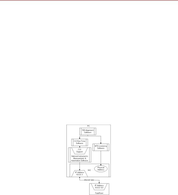
This manual includes information on installing and operating the MTS Alignment software. The 709 Alignment software works in conjunction with the MTS Model 609 Alignment Fixture and strain-gaged specimens. There are options in the 709 Alignment software that allows specimens with fewer channels to be used for alignment.
8 |
Preface |
709 Alignment System |

What You Are Expected to Know
What You Are Expected to Know
Microsoft Windows
knowledge
Testing knowledge
You should have a working knowledge of the Microsoft Windows operating system before you use your system. For example, you should be able to:
•Use the mouse.
•Maneuver around the desktop.
•Locate, open, close, copy, and save documents.
If you are not sure how to do these things, take some time to learn them before you continue.
A premise of this manual is that you have had some experience or exposure to servohydraulic testing, or access to someone who has.
709 Alignment System |
Preface |
9 |

Conventions
Conventions
Notes
Control names
Illustrations
The following paragraphs describe some of the conventions that are used in your MTS manuals.
Notes provide additional information about operating your system or highlight easily overlooked items. For example:
Note Using multiple instances of the scope (on multiple stations) can slow system response time.
References to items shown in windows, including window names, window controls, menu names, and menu commands are shown in bold font style. References to controls on equipment, including keyboards, control panels, and consoles are also shown in bold font style.
Illustrations appear in this manual to clarify text. It is important for you to remember that these illustrations are examples only and do not necessarily represent your actual system configuration or application.
10 |
Preface |
709 Alignment System |
Technical Support
Technical Support
Start with your manuals
Technical support numbers
MTS web site
www.mts.com
E-mail:
Telephone
Fax
The manuals supplied by MTS provide most of the information you will need to use and maintain your equipment. If your equipment includes MTS software, you should look for README files for additional product information.
If you cannot find answers to your technical questions from these sources, you can use the internet, telephone, or fax to contact MTS for assistance. You can also fill out the Problem Submittal Form that is available on the MTS web site and in the back of many MTS manuals that are distributed in paper form.
MTS provides a full range of support services after your system is installed. If you have any questions about a system or product, contact MTS in one of the following ways.
The MTS web site gives you access to our technical support staff by means of a Problem Submittal Form and a Technical Support link.
•Problem Submittal Form:
www.mts.com > Contact MTS > Problem Submittal Form
•Technical Support:
www.mts.com > Contact MTS > Technical Support
info@mts.com
HELPLine 800-328-2255
Weekdays 7:00 A.M. to 6:00 P.M.,
Central Time
952-937-4515
Please include an MTS contact name if possible.
709 Alignment System |
Preface |
11 |
Technical Support
Before you MTS can help you more efficiently if you have the following information contact MTS available when you contact us for support.
Know your site number The site number contains your company number and identifies your equipment and system number type (material testing, simulation, and so forth). The number is usually written on
a label on your MTS equipment before the system leaves MTS. If you do not have or do not know your MTS site number, contact your MTS sales engineer.
Example site number: 571167
When you have more than one MTS system, the system number identifies which system you are calling about. You can find your job number in the papers sent to you when you ordered your system.
Know information from prior technical assistance
Example system number: US1.42460
If you have contacted MTS about this problem before, we can recall your file. You will need to tell us the:
•MTS notification number
•Name of the person who helped you
Identify the problem Describe the problem you are experiencing and know the answers to the following questions.
•How long has the problem been occurring?
•Can you reproduce the problem?
•Were any hardware or software changes made to the system before the problem started?
•What are the model and serial numbers of the suspect equipment?
Know relevant computer information
If you are experiencing a computer problem, have the following information available.
•Manufacturer’s name and model number
•Operating software type and service patch information. Examples:
–Windows Vista
–Windows XP Service Pack 1 (SP2)
•Amount of system memory. Example: 640 MB of RAM.
•Amount of free space on the hard drive in which the application resides. Example: 11.2 GB free space, or 72% free space.
•Current status of hard-drive fragmentation. Example: 3% total fragmentation.
12 |
Preface |
709 Alignment System |
Know relevant software information
If you contact MTS by phone
Identify system type
Be prepared to troubleshoot
Technical Support
For MTS software application problems, have the following information available.
•The software application’s name, version number, build number, and if available, software patch number. This information is displayed briefly when you launch the application, and can typically be found in the “About” selection in the “Help” menu.
Example: Station Manager, Version 3.3A, Build 1190, Patch 4
•The same information for other MTS software included with your system
•Names of other non-MTS applications that are running on your computer, such as screen savers, keyboard enhancers, print spoolers, and so forth
Your call will be registered by a HELPLine agent if you are calling within the United States or Canada. Before connecting you with a technical support specialist, your agent will ask you for your site number, name, company, company address, and the phone number where you can normally be reached.
To assist your HELPLine agent with connecting you to the most qualified technical support specialist available, identify your system as one of the following types:
•Electromechanical materials test system
•Hydromechanical materials test system
•Vehicles test system
•Vehicles component test system
•Aero test system
Prepare yourself for troubleshooting while on the phone.
•Call from a telephone close to the system so that you can try implementing suggestions made over the phone.
•Have the original operating and application software media available.
•If you are not familiar with all aspects of the equipment operation, have an experienced user nearby to assist you.
709 Alignment System |
Preface |
13 |
Technical Support
Write down relevant Prepare yourself in case we need to call you back.
information
• Remember to ask for the notification number.
• Record the name of the person who helped you.
• Write down any specific instructions to be followed, such as data recording or performance monitoring.
After you call MTS logs and tracks all calls to ensure that you receive assistance and that action is taken regarding your problem or request. If you have questions about the status of your problem or have additional information to report, please contact MTS again.
Problem Submittal Form in MTS manuals
In addition to the Problem Submittal Form on the MTS web site, there is also a paper version of this form (postage paid) in the back of many MTS manuals. Use this form to forward problems you are experiencing with your MTS equipment, whether it be software, hardware, manuals, or service. This form includes check boxes that allow you to select when you expect us to respond to your input. We guarantee a timely response—your feedback is important to us.
14 |
Preface |
709 Alignment System |

Introduction
What you need to know
This manual includes information on installing and operating the MTS 709 Alignment software. The 709 Alignment software works in conjunction with the MTS Model 609 Alignment Fixture and strain-gaged specimens. There are options in the 709 Alignment software that allows specimens with fewer channels to be used for alignment.
MTS Systems Corporation assumes that you know how to use your controller. See the appropriate manual for information about performing any controllerrelated step in this manual’s procedures. You are expected to know how to perform the following procedures:
•Turn hydraulic pressure on and off (servo hydraulics only)
•Select a control mode
•Position the load train components
•Zero a sensor signal
•Zero a sensor output
•Use your grips and fixtures
•Define a simple test
•Run a test
Contents |
709 |
Alignment Software |
16 |
|
609 |
Alignment Fixture |
17 |
|
Additional Information |
18 |
|
709 Alignment System |
Introduction |
15 |
709 Alignment Software
709 Alignment Software
MTS 709 Alignment system includes the hardware and software to acquire, analyze, and display bending strains for alignment and bending strain verification purposes. Its graphical interface allows you to quickly align your system or verify how much bending strain is being applied to the specimen. One of the key attributes of this software is that it can separate the bending strain of the specimen from that of the tensile strain.
The best method of determining bending strain is to use a strain-gaged specimen. The software interfaces directly with a strain-gaged specimen and displays bending strain graphically on the monitor of your PC. Continual scanning of bending strains allows you to align your system or verify the bending strain at various levels that will occur during the test. For reports, a text data file can be written to disk and opened in Microsoft Excel for further analysis and customer report generation.
709 Alignment software requires an alignment specimen with a 37-pin D-connector. The software also requires Windows 2000 or later and a dedicated RJ45 ethernet connector. Calibrated load can be displayed with an analog I/O channel.This is required for some certifications such as ASTM E1012. Thin and thick flat specimens, as well as round specimens are supported.
The 709 Alignment System includes data acquisition with conditioning, software, a manual, and connections for ethernet, analog I/O, and an alignment specimen. See “Hardware Installation” on page 27 for addition information.
16 |
Introduction |
709 Alignment System |

609 Alignment Fixture
609 Alignment Fixture
The MTS Model 609 Alignment Fixture for material testing systems that saves time compared to manual alignment methods. A product information manual is provided describing the alignment process and the use of strain-gaged specimens.
The main feature of the 609 is its capability to perform alignment adjustments while the load train is fully loaded. This eliminates any inaccuracies involved in trying to account for the small changes in alignment that frequently occur during the preloading process. In addition, because the fixture remains preloaded at all times, previous alignment adjustments are not lost when small changes in alignment are required.
These alignment fixtures are readily adaptable to other load units as well. Refer to the Model 609 Alignment Fixture Product Information manual (MTS part number 015-031-901) for any special adapter kit that might be required in addition to the alignment fixture.
709 Alignment System |
Introduction |
17 |

Additional Information
Additional Information
The following documents provide additional and background information as it pertains to the importance of proper specimen and machine alignment in materials testing.
•S-400-E: Certified Materials Test Laboratories (CMTL): Metallic Materials
•SAE AS7101 Revision B - NADCAP Alignment Requirements
•ASTM E 1012 - 99: Standard Practice for Verification of Specimen Alignment Under Tensile Load
•Versailles Project on Advanced Materials and Standards (VAMAS) Technical Working Area 13, Low Cycle Fatigue
Recent Intercomparisons on Low Cycle Fatigue and Alignment Measurements
Report No. 41 ISSN 1016-2186 February 2003
•Versailles Project on Advanced Materials and Standards (VAMAS) Technical Working Area 13, Low Cycle Fatigue
A Procedure for the Measurement of Machine Alignment in Axial Testing
Report No. 42 ISSN 1016-2186 February 2003
18 |
Introduction |
709 Alignment System |

Additional Information
CE Hardware Specifications
PARAMETER |
SPECIFICATION |
|
|
|
|
Environmental |
For Indoor Use Only |
|
Ambient Temperature |
5°C (41°F) 40°C (104°F) |
|
Relative Humidity |
10% to 85%, non-condensing |
|
Altitude |
For use at altitudes up to 2000m (6500 ft.) |
|
|
|
|
Power Input |
Power Factor Corrected Universal Input |
|
Input Voltage |
100 to 240 VAC |
|
Input Frequency |
47 to 63 Hz |
|
AC Power |
< 100 Watts |
|
Insulation Over |
Category II |
|
Voltage |
2 |
|
Pollution Degree |
||
|
||
|
|
|
AC Power Disconnect |
Remove the AC power cord from the power supply. |
|
|
This will remove AC power from the 709 Alignment |
|
|
System. |
|
|
Be sure to locate the power supply so you have |
|
|
adequate access to disconnect the power cord from |
|
|
the power supply. |
|
|
|
709 Alignment System |
Introduction |
19 |
Additional Information
20 |
Introduction |
709 Alignment System |
Alignment Procedure Overview
Following is an overview of a typical alignment procedure. It is intended as a guide and will apply to most system configurations.
1.Check the controller setup and tuning before inserting the alignment specimen instrumented with strain gauges: With no specimen clamped in the grips, verify the stroke control tracks without drift. With an expendable specimen clamped in the grips, verify the load control smoothly tracks a slow (less than 1 Hz) function generator ramp.
2.Insure that the specimen is properly connected to the 709 electronics. Wait 20 to 30 minutes to insure there are no temperature gradients.
3.Confirm the specimen geometry and end levels in the specimen tab. The end levels are typically set to the Load @ 2000 µe shown in the second column.
4.In the align tab, check the specimen offsets. Do this by toggling between
None, Current Tare, and Specimen Gauge. Current Tare and Specimen Gauge (stored and averaged offsets) should be very close (within 5%). If they are not, the Specimen Gauge offsets should be cleared and reestablished.
5.With the system in displacement control install the specimen in the lower grip (or upper grip if desired). Clamp that end of the specimen in the grip.
6.Zero the load cell.
7.Move the actuator until the other end of the specimen is in the proper location of the other grip is in position to clamp.
8.Now check to see if the Bent Offset is properly established. Do this by toggling between Current Tare and Bent Offset. Normally, you should see very little change between Current Tare and Bent Offset. Note that Bent Offset is not really needed unless the specimen is not straight (i.e. has manufacturing eccentricities or has been deformed).
709 Alignment System |
Alignment Procedure Overview |
21 |
9.Once the offsets are established, the actual alignment can take place. Make sure the specimen is in the front orientation.
10.Clamp the other grip.
11.Switch the controller to load control.
12.Zero the load command.
13.Start the Alignment Wizard.
14.Follow the adjustment recommendations.
15.Gather data as described in the validation section of the manual.
16.To improve the alignment validation, you might wish to re-measure the bent offset (possibly less prone to 180 degree rotation error when the machine is better aligned) and adjust the alignment a little more.
22 |
Alignment Procedure Overview |
709 Alignment System |

Installation
Installation of the 709 Alignment system consists of both hardware and software installations.
The hardware installation consists of cabling the 709 Alignment System hardware to the network and system controller, connecting the specimen strain gauge connector, and connecting the power cord.
The software installation consists of installing the National Instruments Feild Point software, the .Net Framework, and the 709 Alignment software application.
Contents |
Obtain the License File and NIC Installation 25 |
|
|||
|
Hardware Installation |
27 |
|
|
|
|
709 Alignment System Installation |
27 |
|
||
|
Specimen Installation |
30 |
|
|
|
|
Software Installation |
32 |
|
|
|
|
.Net Framework Installation 33 |
|
|
||
|
709 Alignment Software Installation |
35 |
|
||
|
National Instruments (NI) FieldPoint Installation |
39 |
|||
|
Upgrading The Firmware Located On The FieldPoint FP-2000 |
||||
|
Hardware 45 |
|
|
|
|
|
TCPIP Configuration |
47 |
|
|
|
|
FieldPoint Configuration 52 |
|
|
||
|
MTS Licensing Software Installation (New License) 58 |
||||
|
Updating MTS Licenses (Replacement License) |
64 |
|||
709 Alignment System |
Installation |
23 |
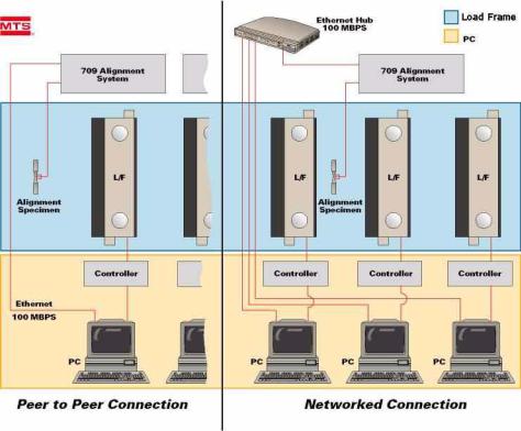
Typical installation environments
For peer to peer connections, a crossover ethernet cable is required.
For networked connections, a standard ethernet cable is required.
24 |
Installation |
709 Alignment System |

Obtain the License File and NIC Installation
Obtain the License File and NIC Installation
Before you install the licensing software later in this section, you will need to obtain a license file.
One license file is supplied for each 709 alignment system.
In a networked connection environment, the license file is created for the PC with the NIC, which will be the “server” and any other PC on the network will be a “client”. The client will use the same license file as used for the server in order to install the MTS licensing software. The server PC will need to be running for the client PC to run the Alignment software.
In most cases, the 709 Alignment system will be configured at MTS and the licence file will be created and shipped with the system. However, in some cases, the 709 Alignment system will be configured on site and you will need to obtain a license file from the factory. If you already have a license, you only need to install the network interface card (NIC) and skip the rest of this procedure.
To obtain the license file, you need to get the Physical Address of the NIC and send that physical address number to MTS. MTS will then send you the license file required for the MTS licensing software installation.
1.The 709 Alignment software comes with two batch files that will retrieve the information MTS needs to provide you with the license file. To start with, insert the 709 Alignment software CD in the computer’s Compact Disk drive. Copy the two batch files (IPConfigAfter.bat and
IPConfigBefore.bat) to your C:\ drive.
2.The first batch file should be run before you install the NIC; this will retrieve physical addresses of any network card(s) that might already be installed and generate a text file that contains that information. Locate the file IPConfigBefore.bat that you just copied to your C:\ drive and double click to run it.When IPConfigBefore.bat is done running, a text file (IPConfigBefore.txt) is generated and placed on your C:\ drive.
709 Alignment System |
Installation |
25 |
Obtain the License File and NIC Installation
3.Install the network interface card. Instructions for installing the NIC into the computer and loading the appropriate drivers are supplied with the card.
4.The second batch file should be run after you install the NIC; this will retrieve the physical addresses of all network cards including the one just installed for the 709 Alignment system. Running this batch file also generates a text file with the physical address information. Locate the file IPConfigAfter.bat that you just copied to your C:\ drive and double click to run it. When IPConfigAfter.bat is done running, a text file (IPConfigAfter.txt) is generated and placed on your C:\ drive.
5.Open the two text files (IPConfigBefore.txt and IPConfigAfter.txt). Compare the two files to find the Physical Address of the Ethernet adapter you just added (which is not in IPConfigBefore.txt). Email the Host Name (which is listed in both files) and the Physical Address to 709license@mts.com.
6.You will be sent the license file on a floppy disk or as an attachment to a reply email. You will need this in Step 6 of the MTS Licensing Software Installation (New License) section.
26 |
Installation |
709 Alignment System |

Hardware Installation
Hardware Installation
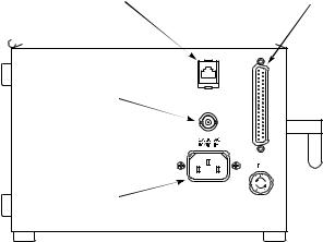
709 Alignment System Installation
Connect the 709 Alignment System as follows:
1.If Load From Analog Input Signal will be used (see “Load Analog Input Signal” on page 66), connect the analog I/O cable from the system controller. (Cabling for this connection must be supplied by the customer.)
For most MTS testing systems, this will be from the TestStar Controller Analog 1 output configured for the load/force signal.
2.Connect the network cable.
The network connection can be to either a site network or directly to the computer.
If the 709 Alignment System will be connected to a site network, ensure that it is on the same subnet as the computer that will be used for the alignment procedure.
3.Connect the alignment specimen cable.
Specimens purchased from MTS have the strain gages wired into a 37-pin D connector. If you are supplying your own specimen, refer to the specimen wiring diagram for connector pin assignments.
4.Plug in the power cord to apply power to the 709 Alignment System. There is no on/off switch on the 709 Alignments System.
Verify all modules in the 709 Alignment System box are seated properly (both down on the base and sideways against the adjacent modules) and have green lights for Power and Ready. If necessary, push on the end to slide the modules towards the power supply.
709 Alignment System |
Installation |
27 |
Hardware Installation
709 Alignment System
cable connections
Network |
Specimen |
connection |
connection |
|
|
|
|
Analog I/O connection (Load cell signal from Test Controller)
Power connection
Standard Configuration
28 |
Installation |
709 Alignment System |
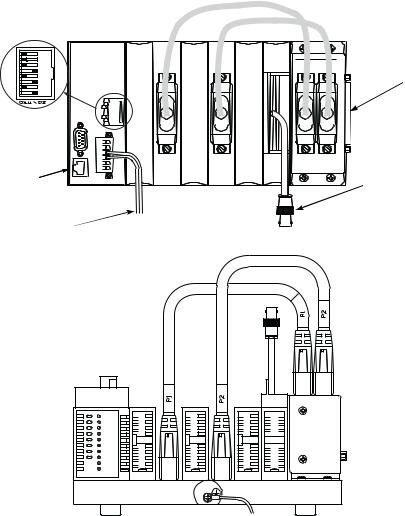
Dip switch settings
Network connection
Power connection
Hardware Installation
Specimen connection
Analog I/O connection (Load cell signal from Test Controller)

 Protective earth ground. Connect the ground terminal to the system safety ground using 14 AWG (1.6mm) wire.
CE Configuration
709 Alignment System |
Installation |
29 |

Hardware Installation
Specimen Installation
When installing the specimen in the grips, ensure the orientation of strain gauge 12 (G12) with respect to the 609 Alignment Fixture matches the following illustrations. G12 must be positioned as shown with respect to the 609 adjustments (A0, A90, A180, A270, C0, C90, C180, C270), for the alignment wizard and 609 Alignment Fixture adjustments to function properly.
Thin |
Thin - rotate 90 degrees |
Thick |
Round |
30 |
Installation |
709 Alignment System |
Loading...