


 Loading...
TRANSISTORIZED INVERTER
INSTRUCTION MANUAL
PARAMETER UNIT
FR-PU04
FR-PU04 |
|
PARAMETER UNIT |
||||||
|
|
|
|
|
|
|
|
|
|
|
|
|
|
|
|
|
|
|
|
|
|
|
|
|
|
|
STF FWD PU
MON SET EXT PU
HELP SHIFT ESC
7 8 9
4 5 6 FWD
1 2 3 REV
0 |
|
|
|
WRITE |
STOP |
|
READ |
RESET |
|||||
|
||||||
PRE-OPERATION INFORMATION
FUNCTIONS
HELP
OPERATION
SPECIFICATION
Chapter 1
Chapter 2
Chapter 3
Chapter 4
Chapter 5

Thank you for choosing the Mitsubishi transistorized inverter option unit.
This instruction manual gives handling information and precautions for use of this equipment. Incorrect handling might cause an unexpected fault. Before using the equipment, please read this manual carefully to use the equipment to its optimum.
Please forward this manual to the end user.
This instruction manual uses the International System of Units (SI). The measuring units in the yard and pound system are indicated in parentheses as reference values.
This section is specifically about safety matters.
Do not attempt to install, operate, maintain or inspect this product until you have read through this instruction manual and appended documents carefully and can use the equipment correctly. Do not use this product until you have a full knowledge of the equipment, safety information and instructions.
In this instruction manual, the safety instruction levels are classified into "WARNING" and "CAUTION".

 WARNING

 CAUTION
Assumes that incorrect handling may cause hazardous conditions, resulting in death or severe injury.
Assumes that incorrect handling may cause hazardous conditions, resulting in medium or slight injury, or may cause physical damage only.
Note that the 
 CAUTION level may lead to a serious consequence according to conditions. Please follow the instructions of both levels because they are important to personnel safety.
A - 1

SAFETY INSTRUCTIONS
1. Electric Shock Prevention
 WARNING
!Do not run the inverter with the front cover removed. Otherwise, you may access exposed high voltage terminals or charging devices and get an electric shock.
!Any person who is involved in the wiring or inspection of this equipment should be fully competent to do the work.
!Always install the inverter before wiring. Otherwise, you may get an electric shock or be injured.
!Operate the keys with dry hands to prevent an electric shock.
2.Additional Instructions
To prevent injury, damage or product failure, please note the following points.
(1) Transportation and mounting
 CAUTION
!Do not install and operate the parameter unit (FR-PU04) if it is damaged or has parts missing.
!Do not stand or rest heavy objects on this equipment.
!Check the inverter mounting orientation is correct.
!The parameter unit (FR-PU04) is a precision device. Do not drop it or subject it to impact.
!Use the product under the following environmental conditions:
Environment |
Conditions |
|
Ambient temperature |
-10°C to +50°C (non-freezing) |
|
Ambient humidity |
90%RH or less (non-condensing) |
|
Storage temperature |
-20°C to +65°C * |
|
Ambience |
Indoors (free from corrosive gas, flammable gas, oil mist, dust |
|
and dirt) |
||
|
||
Altitude, vibration |
Max. 1000m above sea level, 5.9m/s2 or less (conforming to |
|
JIS C 0040) |
||
|
* Temperatures applicable for a short time, e.g. in transit.
A - 2

(2) Test operation and adjustment
 CAUTION
!Before starting operation, confirm and adjust the parameters. A failure to do so may cause some machines to make unexpected motions.
(3) Usage
 WARNING
!The RESETSTOP key is only valid when function setting has been made. Provide an emergency stop switch separately.
!Make sure that the start signal is off before resetting the alarm. A failure to do so may restart the motor suddenly.
!Do not modify the equipment.
 CAUTION
!When parameter clear or all parameter clear is performed, each parameter returns to the factory setting. Re-set the required parameters before starting operation.
(4) Corrective actions for alarm
 CAUTION
!Provide safety backup devices, such as an emergency brake, to protect machines and equipment from hazard if the parameter unit (FR-PU04) becomes faulty.
(5) Disposal
 CAUTION
! Treat as industrial waste.
(6) General instruction
All illustrations given in this manual may have been drawn with covers or safety guards removed to provide in-depth description. Before starting operation of the product, always return the covers and guards into original positions as specified and operate the equipment in accordance with the manual.
A - 3

- CONTENTS -
1 PRE-OPERATION INFORMATION |
|
1 |
|||
1.1 Overview .................................................................................................................... |
|
|
|
1 |
|
1.1.1 Appearance and parts identification...................................................................... |
|
1 |
|||
1.1.2 Explanation of the keys ......................................................................................... |
|
|
|
1 |
|
1.2 Installation and Removal ............................................................................................ |
|
|
|
3 |
|
1.2.1 Installation ............................................................................................................. |
|
|
|
3 |
|
(1) |
Installation to the inverter |
A500 |
F500 E500 -NA -EC -CH |
|
|
|
S500 -NA -EC -CH F500J -CH C500 ........................................................... |
|
3 |
||
(2) |
Using the connection cable (FR-CB2) for connection................................................ |
|
3 |
||
1.2.2 Removal ................................................................................................................ |
|
|
|
4 |
|
(1) |
Removal from the inverter A500 |
F500 E500 -NA -EC -CH |
|
||
|
S500 -NA -EC -CH F500J -CH C500 ........................................................... |
|
4 |
||
(2) |
Removal when the connection cable (FR-CB2) is used ............................................ |
|
4 |
||
1.3 Parameters to Be Checked First ................................................................................ |
|
|
5 |
||
1.3.1 PU display language selection (Pr. 145) ............................................................... |
|
5 |
|||
1.3.2 PU buzzer control (Pr. 990)................................................................................... |
|
|
5 |
||
1.3.3 PU contrast adjustment (Pr. 991) |
.......................................................................... |
|
5 |
||
2 FUNCTIONS |
|
|
|
6 |
|
2.1 Monitoring Function.................................................................................................... |
|
|
|
6 |
|
2.1.1 Display overview ................................................................................................... |
|
|
|
6 |
|
(1) |
Main monitor ............................................................................................................. |
|
|
|
6 |
(2) |
PU level meter A500 |
F500 |
E500 -NA -EC -CH |
S500 -NA -EC -CH |
|
|
F500J -CH C500 ................................................................................................ |
|
|
|
6 |
(3) |
Rotation direction monitoring .................................................................................... |
|
|
6 |
|
(4) |
Operating status indication........................................................................................ |
|
|
6 |
|
(5) |
Operation mode indication ........................................................................................ |
|
|
7 |
|
(6) |
Unit indication ........................................................................................................... |
|
|
|
7 |
(7) |
Alarm indication ........................................................................................................ |
|
|
|
7 |
2.1.2 Using the SHIFT key to change the main screen.................................................... |
|
8 |
|||
2.1.3 Setting the first priority screen (first screen).......................................................... |
|
8 |
|||
2.1.4 Using the HELP key to change the main screen A500 |
F500 |
|
|||
E500 -NA -EC -CH S500 -NA -EC -CH F500J -CH C500 ....................... |
9 |
||||
2.1.5 Using the “PU main display data selection parameter” to change the screen..... |
10 |
||||
Contents
I

2.2 Frequency Setting .................................................................................................... |
|
|
11 |
2.2.1 Direct setting ....................................................................................................... |
|
|
11 |
2.2.2 Step setting ......................................................................................................... |
|
|
11 |
2.2.3 Precautions for frequency setting........................................................................ |
|
12 |
|
2.3 Setting and Changing the Parameter Values ........................................................... |
13 |
||
2.3.1 Direct setting ....................................................................................................... |
|
|
13 |
2.3.2 Step setting ......................................................................................................... |
|
|
14 |
2.3.3 Function-by-function parameter setting |
A500 F500 E500 -NA -EC -CH |
|
|
S500 -NA -EC -CH F500J -CH C500 ........................................................ |
15 |
||
2.3.4 User parameter registration and deletion A500 F500 E500 -NA -EC -CH |
|||
S500 -NA -EC -CH F500J -CH C500 ........................................................ |
16 |
||
(1) Confirmation ........................................................................................................... |
|
|
16 |
(2) Registration............................................................................................................. |
|
|
17 |
(3) Deletion................................................................................................................... |
|
|
18 |
2.3.5 Precautions for setting write ................................................................................ |
|
|
18 |
2.4 Calibration of the Meter (Frequency Meter).............................................................. |
19 |
||
2.4.1 Calibration of the FM terminal |
A500 |
F500 E500 -NA -EC -CH |
|
S500 -NA -EC -CH F500J -CH C500 ........................................................ |
19 |
||
2.4.2 Calibration of the AM terminal |
A500 |
F500 E500 -NA -EC -CH |
|
S500 -NA -EC -CH F500J -CH C500 ........................................................ |
20 |
||
2.5 Adjustment of the frequency setting signals "bias" and "gain" ................................. |
23 |
||
2.5.1 Adjustment procedure A500 |
F500 |
E500 -NA -EC -CH |
|
S500 -NA -EC -CH F500J -CH C500 ........................................................ |
23 |
||
(1) Adjust only the bias and gain frequencies and not adjust the voltage ..................... |
24 |
||
(2) Any point is adjusted with a voltage applied across terminals 2-5 ........................... |
26 |
||
(3) Any point is adjusted without a voltage applied across terminals 2-5 ...................... |
28 |
||
2.6 Copy and Verify Functions ....................................................................................... |
|
|
30 |
2.6.1 Copying the parameter settings .......................................................................... |
|
|
30 |
2.6.2 Verifying the parameters ..................................................................................... |
|
|
31 |
3 HELP |
|
|
32 |
3.1 Overview of the Help Functions ............................................................................... |
|
|
32 |
3.1.1 Help function menu ............................................................................................. |
|
|
32 |
3.1.2 Help function display data ................................................................................... |
|
|
33 |
3.2 Operation Procedures for the Help Functions .......................................................... |
36 |
||
II
3.2.1 Monitor function................................................................................................... |
|
|
|
|
36 |
||
3.2.2 Selection of PU operation (direct input)............................................................... |
|
|
38 |
||||
3.2.3 Selection of the PU jog operation mode A500 |
F500 |
E500 -NA -EC -CH |
|
||||
S500 -NA -EC -CH F500J -CH C500 ........................................................ |
|
|
39 |
||||
(1) |
Calling from the help function menu........................................................................ |
|
|
39 |
|||
(2) |
Calling the key operation guide directly................................................................... |
|
|
39 |
|||
3.2.4 Parameters |
.......................................................................................................... |
|
|
|
|
40 |
|
(1) |
"2 Pr. List" ............................................................................................................... |
|
|
|
|
|
41 |
(2) |
Display of "3 Set Pr. List" |
A500 F500 E500 -NA -EC -CH |
|
||||
|
S500 -NA .........................................................-EC -CH F500J -CH C500 |
|
|
42 |
|||
(3) |
Display of "4 Def. Pr. List" |
A500 F500 E500 -NA -EC -CH |
|
||||
|
S500 -NA .........................................................-EC -CH F500J -CH C500 |
|
|
42 |
|||
(4) |
Display of "5 Def. Pr. List 2" A500 F500 E500 -NA -EC -CH |
|
|||||
|
S500 -NA .........................................................-EC -CH F500J -CH C500 |
|
|
42 |
|||
3.2.5 Parameter Clear.................................................................................................. |
|
|
|
|
43 |
||
3.2.6 Alarm History....................................................................................................... |
|
|
|
|
44 |
||
3.2.7 Alarm Clear ......................................................................................................... |
|
|
|
|
45 |
||
3.2.8 Inverter Reset...................................................................................................... |
|
|
|
|
46 |
||
3.2.9 Troubleshooting |
A500 |
F500 E500 -NA -EC -CH |
S500 -NA -EC -CH |
|
|||
|
F500J -CH ............................................................................................ |
C500 |
|
|
|
47 |
|
(1) |
Troubleshooting .......................................................................................guidance |
|
|
48 |
|||
3.2.10 Selectop |
A500 |
F500 |
E500 -NA -EC -CH |
S500 -NA -EC -CH |
|
||
|
F500J -CH ............................................................................................ |
C500 |
|
|
|
51 |
|
3.2.11 Option................................................................................................................ |
|
|
|
|
|
52 |
|
3.3 Other Precautions .................................................................................................... |
|
|
|
|
53 |
||
3.3.1 Precautions ............................................................for parameter unit operation |
|
|
53 |
||||
(1) |
Precautions ..............................for the digit count and decimal point of input value |
53 |
|||||
(2) |
Other indications ..................................................................................................... |
|
|
|
|
53 |
|
(3) |
Power-on indication................................................................................................. |
|
|
|
53 |
||
4 OPERATION |
|
|
|
|
|
54 |
|
4.1 Operation Modes...................................................................................................... |
|
|
|
|
54 |
||
4.1.1 How to select .......................................................................the operation mode |
|
|
54 |
||||
(1) Switching from ....................external operation mode [EXT] to PU operation mode [PU] |
54 |
||||||
(2) Switching from .........................PU operation mode [PU] to external operation mode [EXT] |
54 |
||||||
(3) |
Switching to .......................................the external / PU combined operation mode |
|
54 |
||||
4.2 PU Operation ........................................................................................................... |
|
|
|
|
|
56 |
|
|
|
|
|
III |
|
|
|
Contents

4.2.1 Ordinary operation............................................................................................... |
56 |
4.2.2 PU jog operation A500 F500 E500 -NA -EC -CH S500 -NA -EC -CH |
|
F500J -CH C500 ............................................................................................ |
57 |
4.3 Combined Operation (Operation using external input signals and PU).................... |
58 |
4.3.1 Entering the start signal from outside and setting the running frequency from the |
|
PU (Pr. 79=3) ...................................................................................................... |
58 |
4.3.2 Entering the running frequency from outside and making start and stop from the |
|
PU (Pr. 79 = 4) .................................................................................................... |
59 |
4.3.3 Entering the start signal and multi-speed signal from outside and setting multiple |
|
speeds from the PU ............................................................................................ |
60 |
5 SPECIFICATION |
61 |
5.1 Specifications ........................................................................................................... |
61 |
5.1.1 Standard specifications ....................................................................................... |
61 |
5.1.2 Outline drawing ................................................................................................... |
62 |
5.1.3 Panel cutting drawing .......................................................................................... |
62 |
IV
CHAPTER 1 PRE-OPERATION
INFORMATION
This chapter provides the basic "pre-operation information (overview)" for use of this product.
Always read the instructions before using the equipment
1.1 |
Overview..................................................................... |
|
|
1 |
|
1.2 |
Installation and Removal............................................. |
3 |
|||
1.3 |
Parameters to Be Checked First................................. |
5 |
|||
The FR-PU04 can be used with the Mitsubishi transistorized |
|||||
inverters. However, there are restrictions on some functions |
|||||
depending on the model. |
|
|
|||
Note that the following representations are used in this |
|||||
manual. |
|
|
|
|
|
A500 |
F500 |
E500 -NA |
-EC -CH |
S500 -NA -EC -CH |
|
Usable |
Unusable |
Unusable |
Usable |
Usable Unusable |
|
Chapter 1
Chapter 2
Chapter 3
Chapter 4
Chapter 5
1.1 Overview
PRE-OPERATION INFORMATION
1.1.1 Appearance and parts identification
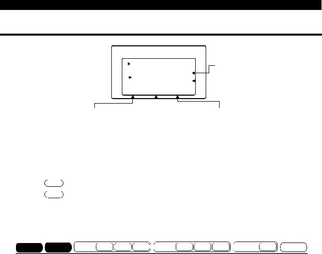
Unpack the parameter unit from the carton, check the name plate on the back, and make sure that the product has not been damaged before using the equipment.
|
|
|
Monitor section |
|
|
|
|
|
|
|
Wide liquid crystal screen |
|
|
|
(13 characters 4 lines, |
|
|
|
with backlight) |
|
|
|
Interactive parameter setting |
FR-PU04 |
PARAMETER UNIT |
Help function, troubleshooting |
|
|
|
|
guidance. |
|
|
|
|
|
21 different monitor data |
|
Monitor mode |
|
STF FWD PU |
|
(frequency, current, power, etc.) |
||
|
|
|
|
Operation mode selection key |
||
selection key |
|
|
|
|
||
|
|
|
PU |
|
||
Setting mode |
MON |
SET |
EXT |
Escape key |
||
|
|
|
|
|||
selection key |
HELP |
SHIFT |
ESC |
|
||
|
Frequency changing keys |
|||||
Help mode |
7 |
8 |
9 |
|
||
|
|
|||||
selection key |
4 |
5 |
6 |
FWD |
Operation command keys |
|
Shift key |
||||||
1 |
2 |
3 |
REV |
Keys used to command |
||
Function and |
0 |
READ |
WRITE |
RESET |
forward rotation, reverse |
|
rotation and stop (reset at |
||||||
|
|
|
|
STOP |
|
|
number keys |
|
|
|
|
alarm occurrence). |
|
(0 to 9) |
|
|
|
|
Write, read keys |
|
 Connector
Model
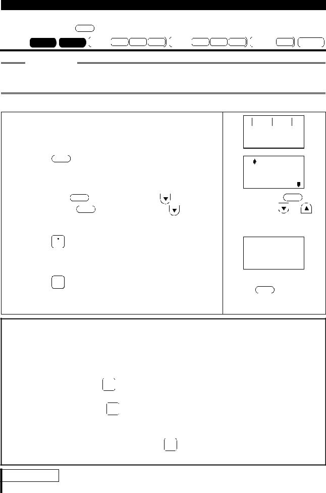
1.1.2 Explanation of the keys
|
|
Key |
Description |
|
SET |
key |
|
Used to select the parameter setting mode. |
|
|
key |
|
Used to display the main monitor. |
|
ESC |
key |
|
Operation cancel key. |
|
HELP key |
|
Used to select the help mode. |
|
|
SHIFT key |
|
Used to shift to the next item in the setting or monitoring mode. |
||
Number keys ( 0 to 9 ) |
Used to enter a frequency, parameter number or set value. |
|||
|
|
|
|
|
key |
|
Used to select the external operation mode. |
|
|
|
|
|
|
|
PU key |
|
Used to select the PU operation mode. |
|
|
|
|
|
|
|
|
|
|
Used to keep on increasing or decreasing the running |
|
|
|
|
frequency. Hold down to vary the frequency. |
|
|
|
|
Press either of these keys on the setting mode screen to change |
|
|
|
|
the parameter setting sequentially. |
|
|
|
|
On the monitoring, parameter or help menu screen, these keys |
|
and |
keys |
are used to move the cursor. |
|
|
|
|
|
Hold down the SHIFT key and press either of these keys to |
|
|
|
|
advance or return the display screen one page. |
|
|
|
|
In the parameter copy or verify mode, the |
key is used as a |
|
|
|
verify key. |
|
|
|
|
|
|
FWD key |
|
Forward rotation command key. |
|
|
REV key |
|
Reverse rotation command key. |
|
|
RESETSTOP key |
|
• Stop command key. |
|
|
|
|
|
• Used as a reset key when an alarm occurs. |
|
1
|
|
|
PRE-OPERATION INFORMATION |
|
|
|
|
|
|
|
|
|
|
|
|
Key |
Description |
|
|
|
|
|
|
• Used to write a set value in the setting mode. |
|
|
|
WRITE key |
• Used as a clear key in the all parameter clear or alarm history clear |
|
|
|
||
|
|
|
mode. |
|
|
|
|
|
|
Used also as a decimal point key. |
|
|
|
|
|
|
Used as a parameter number read key in the setting mode. |
|
|
|
|
|
|
Used as an item select key on the menu screen such as parameter list |
|
|
|
|
|
key |
or monitoring list. |
|
|
|
|
|
|
|
|
||
|
|
|
Used as an alarm definition display key in the alarm history display |
|
|
|
|
|
|
mode. |
|
|
|
|
|
|
Used as a command voltage read key in the calibration mode. |
|
|
|
|
|
|
13 character × 4 line liquid crystal display screen shows monitoring |
|
|
|
Display |
data, such as frequency, motor current and I/O terminal states, as well |
|
|
|
||
|
|
|
as troubleshooting guidance and other information. |
|
|
|
|
|
|
Used for connection of the parameter unit with the inverter. You may |
|
|
|
Connector |
either connect the unit directly or use the connection cable (FR-CB2 |
) |
|
|
||
|
|
|
for connection. |
|
|
|
|
|
|
FR-PU04 |
|
|
|
Model |
MITSUBISHI ELECTRIC CORPORATION |
|
|
|
||
|
|
1 |
||||
|
|
|
||||
|
|
|
MADE IN JAPAN |
|
|
|
|
|
|
|
|
|
|
|
|
|
|
|
|
|
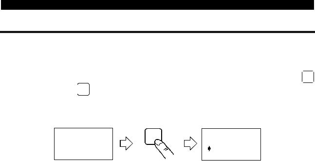
CAUTION
1.Do not use a sharp-pointed tool to push the keys.
2.The display is a liquid crystal display. Do not press your fingers against the display.
2

1.2 Installation and Removal
PRE-OPERATION INFORMATION
To ensure safety, install and remove the parameter unit after switching the power off.
1.2.1 Installation
(1) Installation to the inverter
A500 F500 E500 -NA -EC -CH S500 -NA -EC -CH F500J -CH C500
1)Remove the operation panel (FR-DU04) and accessory cover.
2)Insert the parameter unit straight and fit it securely.
(2) Using the connection cable (FR-CB2) for connection
REMARKS
For details of the connection cable (FR-CB2), refer to the connection cable (FR-CB2) instruction manual.
 When connecting to the FR-A500/ F500/ E500 series.
1)Remove the operation panel.
2)Insert the cable plugs securely into the connectors of the inverter and parameter unit (FR-PU04) along the cable guides until the stoppers are actuated.
Joint connector
|
|
Tab |
Tab |
Tab |
Tab |
FR-A500 / F500 series. |
FR-E500 series. |
CAUTION
Install the operation panel only when the front cover is installed.
3
PRE-OPERATION INFORMATION
 When connecting to the FR-S500/ F500J/ C500 series.
1)Remove the front cover.
2)Insert the cable plugs securely into the connectors of the inverter and parameter unit (FR-PU04) along the cable guides until the tabs snap into place.
connector
Tab
Tab
REMARKS |
|
You can cut off the hook of the wiring cover |
|
to perform the wiring. |
|
You can insert or pull the connector with |
hook |
the front cover installed. |
1 |
1.2.2 Removal
(1) Removal from the inverter
A500 F500 E500 -NA -EC -CH S500 -NA -EC -CH F500J -CH C500
Hold down the top button of the FR-PU04 and pull the parameter unit toward you, using the catches as a support.
Catches
(2) Removal when the connection cable (FR-CB2) is used
Hold down the tab at the cable end and gently pull the plug.
4

1.3 Parameters to Be Checked First
PRE-OPERATION INFORMATION
Change the following parameter settings as required.
For the changing procedures, refer to page 13.
1.3.1 PU display language selection (Pr. 145)
By setting the Pr. 145 "PU display language selection" value, you can select the language displayed on the parameter unit.
Pr. 145 Setting |
Display Language |
0 |
Japanese (factory setting of Japanese domestic version) |
1 |
English (factory setting of NA version) |
2 |
German |
3 |
French |
4 |
Spanish |
5 |
Italian |
6 |
Swedish |
7 |
Finnish |
1.3.2 PU buzzer control (Pr. 990)
By setting the Pr. 990 "PU buzzer control" value, you can select to either generate or mute the "beep" which sounds when you press any of the parameter unit keys.
Pr.990 Setting |
Description |
0 |
No sound |
1 |
Sound generated (factory setting) |
1.3.3 PU contrast adjustment (Pr. 991)
By setting the Pr. 991 "PU contrast adjustment" value, you can adjust the contrast of the parameter unit LCD.
Pr. 991 Setting |
|
|
|
|
|
"0" |
"63" |
||
0 to 63 |
|
|
|
|
|
|
|
|
|
|
Light |
Dark |
||
|
|
|
|
|
Note: If the WRITE key is not pressed, the PU contrast setting is not stored.
Inverter |
Pr. 991 factory setting |
FR-A500 |
53 |
FR-F500 |
53 |
FR-E500 |
58 |
Inverter |
Pr. 991 factory setting |
FR-S500 |
58 |
FR-F500J |
58 |
FR-C500 |
58 |
5

CHAPTER 2 FUNCTIONS
This chapter describes the "functions" for use of this product.
Always read the instructions before using the equipment.
2.1 |
Monitoring Function ........................................................ |
6 |
2.2 |
Frequency Setting......................................................... |
11 |
2.3 |
Setting and Changing the Parameter Values ................ |
13 |
2.4 |
Calibration of the Meter (Frequency Meter) .................. |
19 |
2.5 |
Adjustment of the frequency setting signals |
|
|
"bias" and "gain" ........................................................... |
23 |
2.6 |
Copy and Verify Functions............................................ |
30 |
Chapter 1
Chapter 2
Chapter 3
Chapter 4
Chapter 5
2.1 Monitoring Function
FUNCTIONS
2.1.1 Display overview
(2) PU level meter |
|
|
|
|
|
|
|
|
|
|
|
|
|
|
|
|
|
|
|
|
|
|
|
|
(7) |
Alarm indication |
|
|
|
|
|
|
|
|
|
|
|
|
|
|
|
|
|
|
|
|
|
|
|
|
|
||||
|
|
120.00Hz |
|||||||||||||||||||||||||
(1) Main monitor |
|
|
|
|
|
|
|
|
|
|
|
|
|
|
|
|
|
|
|
|
|
|
|
|
OL |
|
|
|
STF FWD PU |
(6) |
Unit indication |
||||||||||||||||||||||||
|
|
|
|||||||||||||||||||||||||
(3) Rotation direction |
|
|
|
|
(5) Operating mode |
||||||||||||||||||||||
(4) Operating status |
|||||||||||||||||||||||||||
monitoring |
|
|
indication |
indication |
|||||||||||||||||||||||
(1) Main monitor
Shows the output frequency, output current, output voltage, alarm history and other monitor data.
•Using the SHIFT key to change to the next screen (refer to page 8)
•Using the HELP key to change to the next screen (refer to page 9)
•Using Pr. 52 "PU main display data selection" to change the main screen (refer to page 10)
(2) PU level meter
A500 F500 E500 -NA -EC -CH S500 -NA -EC -CH F500J -CH C500
Setting the Pr. 53 "PU level display data selection" displays the data selected on the 5% graduated level meter.
Refer to the inverter instruction manual for details.
(3) Rotation direction monitoring
Indicates the direction of rotation of the motor. STF : Forward rotation
STR: Reverse rotation
- - - : No command or both STF and STR on
(4) Operating status indication
Shows the operating status of the inverter. STOP: During stop
FWD : During forward rotation REV : During reverse rotation JOGf : During job forward ratation JOGr : During jog reverse rotation
6

FUNCTIONS
(5) Operation mode indication
Displays the status of the operation mode. EXT : External operation mode
PU : PU operation mode EXTj : External jog mode PUj : PU jog mode
NET : Link operation mode
PU+E : External / PU combined operation mode PRG : Programmed operation mode
(6) Unit indication
Shows the unit of the main monitor.
(7) Alarm indication
Displays an inverter fault as an alarm.
CAUTION
This function varies with the inverter model.
- - - : Normal |
|
|||
OL |
: |
Stall (current) |
|
|
oL |
: |
Stall (voltage) |
|
|
RB : |
Regenerative brake pre-alarm |
|
||
|
||||
TH : |
Electronic overcurrent protection pre-alarm |
2 |
||
PS : |
PU stop |
|||
|
||||
|
|
|
|
|
7

FUNCTIONS
2.1.2 Using the SHIFT key to change the main screen
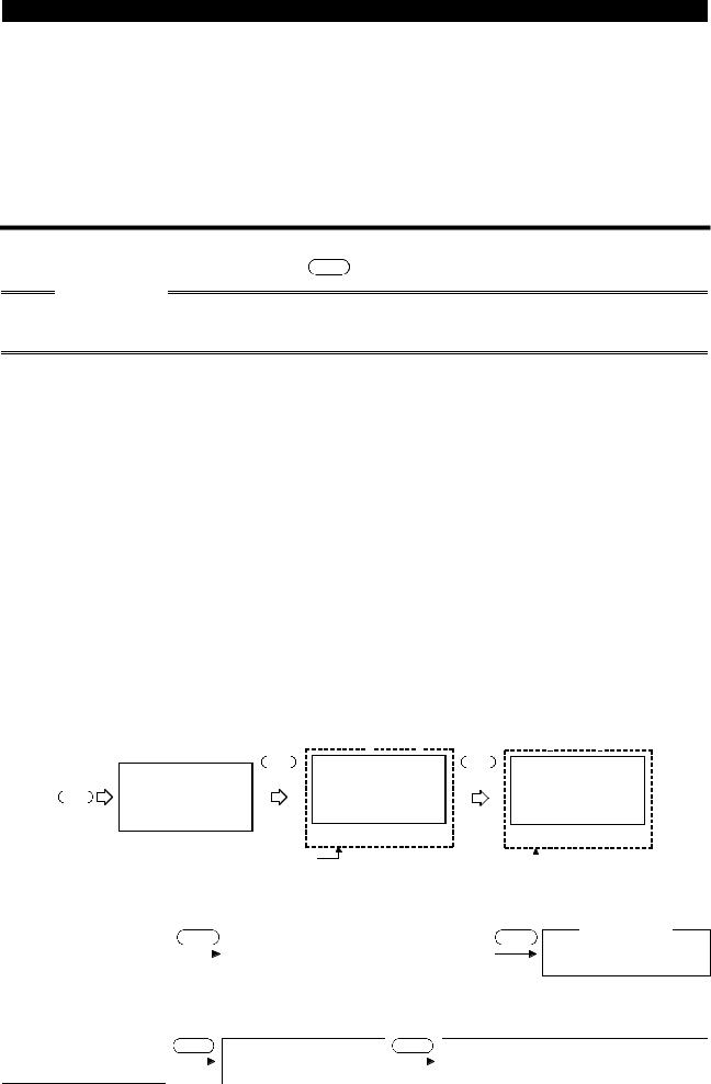
When "0" (factory setting) is set in Pr. 52 "PU main display data selection", merely pressing the SHIFT key calls 6 different monitor screens in sequence.
Switch power on or press MON key.
First priority |
First |
|
|
|
|
|
|
|
|
|
|
monitor |
|
|
|
0.00 |
|
frequency |
|
|
|
Hz |
|
(Output |
|
|
|
|
|
monitor) |
--- |
STOP EXT |
|||
|
|
|
|
|
|
SHIFT
Second
(Output current
monitor) 0.00A
|
|
|
--- |
STOP |
EXT |
|||
|
|
|
|
|
SHIFT |
|
|
|
|
|
|
Third(*) |
|
|
|||
(Output voltage |
|
|
|
|
|
|
||
|
|
|
|
|
|
|||
|
|
|
0.0V |
|||||
monitor) |
|
|
|
|||||
A500 |
|
F500 |
--- |
STOP |
EXT |
|||
E500 |
-NA |
-EC -CH |
|
|
|
|
||
S500 |
-NA -EC -CH |
SHIFT |
|
|
||||
F500J -CH |
C500 |
Fourth |
|
|
||||
ALARM HISTORY
(Alarm history
monitor) <READ>
SHIFT
Sixth
(3-step monitor) Up to 3 monitor data types are displayed in line from top of the left column.
(Selective
monitor)
0.00Hz
0.00A
0.0V
--- STOP EXT
SHIFT
Fifth
OTHERS
<HELP>
SHIFT SHIFT
1 UVT 5
2 UVT 6
|
READ |
3 |
7 |
|
|
4 |
8 |
Setting the first priority monitor sets it here.
HELP
Refer to page 9
*For the FR-S500 series, the third monitor is also output current monitor.
2.1.3 Setting the first priority screen (first screen)
Set the screen which appears first when power is switched on or the  key is pressed.
 When you press the WRITE key with any screen other than ALARM HISTORY and OTHERS being displayed, that screen is set as the first priority screen and will be displayed first.
 You cannot set "15 I/P Signal", "16 O/P Signal" or multiple simultaneous screens as the first priority screen.
8
FUNCTIONS
2.1.4 Using the HELP key to change the main screen
A500 F500 E500 -NA -EC -CH S500 -NA -EC -CH F500J -CH C500
CAUTION
The functions vary with the inverter model. (Refer to page 32 for details of the help functions.)
 Example: Select the output current peak value monitor.
1) Press the  key.
key.
The parameter unit is placed in the monitoring mode. 0.00
Hz
|
|
|
|
|
|
|
|
|
|
STOP PU |
|
|
|||
|
|
|
|
|
|
|
|
|
|
|
|||||
|
|
|
|
|
|
|
|
|
|
|
|
||||
2) |
Press the HELP key. |
|
1 |
|
|
Frequency |
|
|
|||||||
|
The monitoring list appears. |
|
2 |
|
|
Current |
|
|
|
|
|||||
|
|
|
|
|
3 |
|
|
Voltage |
|
|
|
|
|||
|
|
|
|
|
4 |
|
|
Alarm His |
|
|
|||||
|
|
|
|
|
|
|
|
|
|
||||||
3) |
Hold down the SHIFT key and press the |
key twice, |
...... Hold down SHIFT and |
|
|
||||||||||
|
then release the SHIFT key, and press the |
key twice. |
press the |
or |
|
|
|||||||||
|
(Moves the cursor to Peak I.) |
|
key to shift the screen |
|
|
||||||||||
|
|
one page. |
|
|
|
|
|||||||||
|
|
|
|
|
|
|
|
|
|||||||
4) |
Press the |
|
key. |
|
|
|
|
|
|
|
|
|
A |
|
|
|
|
|
|
|
|
|
|
|
|
|
|
||||
|
|
|
|
|
|
|
|
|
|
|
|
||||
|
The screen shown on the right appears.(*1) |
|
|
|
|
|
|
0.00 |
|
|
|||||
|
|
|
|
|
|
|
|
|
|
STOP |
EXT |
|
|
||
|
|
|
|
|
|
|
|
|
|
|
2 |
||||
5) |
Press the WRITE key. |
|
...... Subsequently press |
|
|||||||||||
|
The screen in step 4) is set as the first priority screen. |
the SHIFT key to call |
|
|
|||||||||||
|
another monitor |
|
|
||||||||||||
|
(*2) |
|
|
|
|
|
|||||||||
|
|
|
|
screen. |
|
|
|
|
|||||||
*1. The selective monitor screen is not yet the first priority screen in the above step 4) when the  key was pressed. Hence, the selected item is erased from memory as soon as the power is switched off or another operation mode (such as external operation) is selected.
In this case, the item must be selected again in the above procedure. When you press the WRITE key to select the first priority screen, the selected item is stored in memory.
*2. In step 5) where the WRITE key was pressed in the above setting example, the "output current peak" selected here is first displayed with priority when the other operation mode is switched to the monitoring mode. To give first priority to another monitor screen, press the WRITE key with that monitor screen being displayed. (Refer to page 8.)
REMARKS
Refer to page 32 for details of the help functions.
9
FUNCTIONS
 When "current monitor" or "power monitor" is selected
Note that any current or power not more than 5% of the rated inverter current cannot be detected and displayed.
Example:When a small motor is used with a large-capacity inverter (a 0.4kW motor is used with a 55kW inverter), power monitor is inoperative.
2.1.5Using the “PU main display data selection parameter” to change the screen
By setting the Pr. 52 value, you can change the "second" and "third" screen displays from the first priority screen using the SHIFT key.
CAUTION
The functions vary with the inverter model. (Refer to the inverter instruction manual for details of the “PU main display data selection parameter”.)
Inverter |
|
|
|
|
|
|
|
|
|
|
|
Pr. 52 Setting |
|
|
|
|
|
|
|
|
|
|
||||||||
|
Setting values displayed in place |
Setting values displayed in |
||||||||||||||||||||||||||||
|
|
|
|
of output current monitor |
place of output voltage monitor |
|||||||||||||||||||||||||
|
|
|
|
17 (load meter) |
|
|
|
|
|
|
|
|
|
|
19 |
(position pulse) |
||||||||||||||
FR-A500 series |
|
18 (motor excitation current) |
20 |
(cumulative energization time) |
||||||||||||||||||||||||||
|
24 (motor load factor) |
|
|
|
|
|
|
|
|
|
22 |
(orientation status) |
||||||||||||||||||
|
|
|
|
|
|
|
|
|
|
|
|
|
23 |
(actual operation time) |
||||||||||||||||
|
|
|
|
|
|
|
|
|
|
|
|
|
|
|
|
|
|
|
||||||||||||
|
|
|
|
|
|
|
|
|
|
|
|
|
|
|
|
|
|
|
25 |
(cumulative power) |
||||||||||
|
|
|
|
17 (load meter) |
|
|
|
|
|
|
|
|
|
|
20 |
(cumulative energization time) |
||||||||||||||
FR-F500 series |
|
24 (motor load factor) |
|
|
|
|
|
|
|
|
|
23 |
(actual operation time) |
|||||||||||||||||
|
|
|
|
|
|
|
|
|
|
|
|
|
|
|
|
|
|
|
25 |
(cumulative power) |
||||||||||
FR-E500 series |
|
|
|
|
|
|
- |
|
|
|
|
|
|
|
|
|
23 |
(actual operation time) |
||||||||||||
FR-S500/F500J/ |
|
|
|
|
|
|
- |
|
|
|
|
|
|
|
|
|
|
|
- |
|
|
|
|
|||||||
C500 series |
|
|
|
|
|
|
|
|
|
|
|
|
|
|
|
|
|
|
|
|
|
|||||||||
|
|
|
|
|
|
|
|
|
|
|
|
|
|
|
|
|
|
|
|
|
|
|
|
|
|
|
|
|||
|
|
|
|
|
|
|
|
|
|
|
|
|
|
|
|
|
|
|
|
|
|
|
|
|
|
|
|
|
|
|
Factory setting |
|
|
|
|
|
|
|
|
|
|
|
|
|
|
|
|
|
|
|
|
|
|
|
|
|
|
|
|
||
* The monitor displayed at powering on is the first priority monitor. |
|
|
|
|
|
|
|
|
|
|
||||||||||||||||||||
Refer to page 8 for the setting method of the first priority monitor. |
|
|
|
|
|
|
|
|
|
|
||||||||||||||||||||
First priority monitor |
|
|
Second monitor |
|
|
|
|
|
|
Third monitor |
||||||||||||||||||||
|
|
|
|
|
|
0.00 |
|
SHIFT |
|
|
|
|
|
|
0.00 |
|
A |
|
SHIFT |
|
|
|
|
|
|
|
0.0 |
|
V |
|
|
|
|
|
|
|
|
|
|
|
|
|
|
|
|
|
|
|
|
|
|
|
|
||||||||
|
|
|
|
|
|
|
Hz |
|
|
|
|
|
|
|
|
|
|
|
|
|
|
|
|
|
|
|||||
|
|
|
|
|
|
|
|
|
|
|
|
|
|
|
|
|||||||||||||||
|
|
|
|
|
|
|
|
|
|
|
|
|
|
|
|
|
|
|
|
|
|
|
|
|||||||
MON |
|
|
|
|
|
|
||||||||||||||||||||||||
|
|
|
|
|
|
|
|
|
|
|
|
|
|
|
|
|
|
|
|
|
|
|
|
|
|
|
|
|||
|
|
|
|
STOP EXT |
|
|
|
|
|
STOP EXT |
|
|
|
|
|
|
|
STOP EXT |
||||||||||||
|
|
|
|
|
|
|
|
|
|
|
|
|
|
|
||||||||||||||||
|
|
|
|
(Output current monitor) |
|
(Output voltage monitor) |
||||||||||||||||||||||||
(Output frequency monitor) |
|
|||||||||||||||||||||||||||||
|
|
|
|
|
|
|
|
|
|
|
|
|
|
|
|
|
|
|
|
|
|
|||||||||
|
|
|
|
First |
1) |
|
|
|
|
Second |
|
2) |
|
|
|
|
|
Third |
||||||||||||
1)For the set value of "17, 18, 24", their monitors are displayed at the second monitor instead of output current monitor.
First priority monitor |
|
SHIFT |
|
Second monitor |
|
|
Output frequency |
Monitor of the set value |
|||||
|
||||||
monitor |
|
|
of "17, 18, 24" |
|||
Third monitor
SHIFT
Output voltage monitor
2)For the set value of "19 to 23, 25", their monitors are displayed at the third monitor instead of output voltage monitor.
First priority monitor |
|
SHIFT |
|
Second monitor |
|
SHIFT |
|
Second monitor |
|
Output frequency |
|
Output current |
Monitor of the set value |
||||||
|
|
|
|||||||
monitor |
|
|
monitor |
|
|
of "19 to 23, 25" |
|||
10
2.2 Frequency Setting
FUNCTIONS
Make this setting in the PU operation mode.
REMARKS
The external start signal (STF or STR) must not be ON to switch from external operation mode to PU operation mode.
2.2.1 Direct setting
 Operation procedure (Changing from 0Hz setting to 60Hz setting)
1) |
Press the PU key. |
.......The frequency setting |
DIRECTLY |
|||
|
|
screen appears. |
Set |
|
0.00Hz |
|
|
|
|
|
|
|
|
|
|
|
|
|
|
|
2) |
Press the 6 and 0 |
.......Enter 60Hz. |
DIRECTLY |
|||
|
keys. |
|
Set |
|
0.00Hz |
|
|
|
|
|
60Hz |
||
|
(Remarks) |
|
|
|
|
|
3) |
Press the WRITE key. |
.......Register the 60Hz |
DIRECTLY |
|||
|
|
setting. (Setting |
|
|
60.00Hz |
|
|
|
|
Completed |
|||
|
|
complete) |
|
|||
REMARKS
 If you entered an incorrect value, press the ESC key to return to the pre-entry state.
2.2.2 Step setting
|
|
|
|
|
|
|
|
|
|
2 |
|
1) |
Press the PU key. |
.......The frequency setting |
DIRECTLY |
|
|||||
|
|
|||||||||
|
|
|
|
screen appears. |
Set |
|
0.00Hz |
|
||
|
|
|
|
|
|
|
|
|
|
|
|
|
|
|
|
|
|
|
|
|
|
|
2) |
Press the / |
key to enter any value (60.00Hz). |
DIRECTLY |
|
|
||||
|
|
(Remarks 1) |
|
|
|
|||||
|
|
|
|
Set |
|
0.00Hz |
|
|||
|
|
You can set any value between the maximum frequency |
|
|
60.00Hz |
|
||||
|
|
(Pr. 1) and minimum frequency (Pr. 2). |
|
|
|
|
|
|
||
|
3) |
Press the WRITE |
key. |
.......Register the 60Hz |
DIRECTLY |
|
|
|||
|
|
|
|
setting. (Setting |
|
|
60.00Hz |
|
|
|
|
|
|
|
|
Completed |
|
|
|||
|
|
|
|
complete) |
|
|
||||
REMARKS
1.If you entered an incorrect value, press the ESC key to return to the pre-entry state.
2.During operation, you can also make the step setting to change the running frequency. If you operate the  /
/ key in the monitor mode, however, the frequency will not stop when you release the key but will further increase (or decrease). (Since the
  /
/ key is used to vary the preset frequency, the varied frequency will differ from the output frequency.)
11
FUNCTIONS
2.2.3 Precautions for frequency setting
1)Pr. 79 "operation mode selection" must have been set to make the "PU operation mode" valid.
2)In the monitor mode, you cannot make the setting directly (refer to page 11) to set the running frequency. Perform the step setting (refer to page 11) and press the WRITE key, or press the PU key to deselect the monitor mode before starting frequency setting.
Monitor mode |
Deselect monitor |
Frequency setting |
||||||||||||
mode |
|
screen |
||||||||||||
|
|
|
|
|
|
|
|
|
|
|
|
|
||
|
|
|
|
|
|
|
|
|
|
|
|
PU |
DIRECTLY |
|
|
|
|
|
|
|
|
|
|
|
|
|
|||
|
|
|
30.00Hz |
|
Set |
30.00Hz |
||||||||
|
|
|
|
|
|
|||||||||
STF FWD PU
12

2.3 Setting and Changing the Parameter Values
FUNCTIONS
The inverter has a number of parameters. Using the PU, you can choose parameters required for operation and set and/or change their values as appropriate according to the load and running conditions. Set "1" in Pr. 77 "parameter write inhibit selection" to inhibit write.
CAUTION
The functions vary with the inverter. (Refer to the inverter instruction manual for details of the parameters.)
2.3.1 Direct setting
 Operation procedure (Example: Reading and writing the Pr. 8 "deceleration time" value)
|
1) |
Press the PU key. |
DIRECTLY |
|
|
|||||
|
|
The frequency setting screen appears. |
Set |
0.00Hz |
|
|
||||
|
|
|
|
|
|
|
||||
|
|
|
|
|
|
|
|
|
|
|
|
2) |
Press the |
SET key. |
SETTING MODE |
|
|
||||
|
|
The parameter unit enters the parameter setting mode. |
Set |
Pr. NO. |
|
|
||||
|
|
|
|
|
|
FOR PR. List |
|
|
||
|
|
|
|
|
|
<HELP> |
|
|
||
|
|
|
|
|
|
|
|
|
|
|
|
3) |
Press the required parameter number 8 . |
SETTING MODE |
|
|
|||||
|
|
The screen on the right appears. |
Pr. NO. |
|
|
|||||
|
|
|
|
|||||||
|
|
|
8 |
|
2 |
|||||
|
|
|
|
|
|
<READ> |
|
|||
|
|
|
|
|
|
|
|
|
|
|
|
4) |
Press the |
|
|
key. |
8 |
Dec. T1 |
|
|
|
|
|
|
|
|
||||||
|
|
The current setting appears on the display. |
|
5. 0S |
|
|
||||
|
|
|
|
|
|
|
||||
|
|
|
|
|
|
|
|
|
||
|
5) |
Enter the required value ( 1 8 0 ). (Example: To set |
8 |
Dec. T1 |
|
|
||||
|
|
to 180s) |
|
|
|
|
5. 0S |
|
|
|
|
|
A new setting appears on the display.(*) |
|
180S |
|
|
||||
|
|
|
|
|
|
|
||||
|
|
|
|
|
|
|
|
|
||
|
6) |
Press the WRITE key. |
8 |
Dec. T1 |
|
|
||||
|
|
The setting is stored into memory. |
|
|
||||||
|
|
|
180. 0S |
|
|
|
||||
|
|
If an error is displayed when you press the WRITE key, refer |
Completed |
|
|
|||||
|
|
to page 47. |
|
|
|
|
|
|||
|
7) |
Press the SHIFT key to move to the next parameter |
9 |
Set THM |
|
|
||||
|
|
(Pr. 9) and call the current setting. Then, press the |
|
2. 55A |
|
|
||||
|
|
SHIFT key to advance to the next parameter. |
|
|
|
|
|
|||
|
|
|
|
|
|
|
|
|
|
|
|
|
|
|
|
|
|
|
|
|
|
|
REMARKS |
|
|
|
|
|
|
|
|
|
|
*If you entered an incorrect value, press the ESC key to return to the pre-entry state. |
|
|
|||||||
13
Loading...