


 Loading...
INVERTER
Plug-in option
FR-A8NC
INSTRUCTION MANUAL


 communication function
PRE-OPERATION INSTRUCTIONS |
1 |
|
|
|
|
|
|
INSTALLATION |
2 |
|
|
|
|
|
|
WIRING |
3 |
|
|
|
|
|
|
INVERTER SETTING |
4 |
|
|
|
|
|
|
FUNCTION OVERVIEW |
5 |
|
|
|
|
|
|
I/O SIGNAL LIST |
6 |
|
|
|
|
DETAILS OF INPUT AND OUTPUT |
7 |
SIGNALS |
|
|
|
PROGRAMMING EXAMPLES |
8 |
|
|
|
|
HOW TO CHECK FOR ERROR USING |
9 |
THE LEDS |

Thank you for choosing this Mitsubishi Electric inverter plug-in option.
This Instruction Manual provides handling information and precautions for use of this product. Incorrect handling might cause an unexpected fault. Before using this product, read all relevant instruction manuals carefully to ensure proper use.
Please forward this Instruction Manual to the end user.
Safety instructions
Do not attempt to install, operate, maintain or inspect this product until you have read this Instruction Manual and appended documents carefully. Do not use this product until you have a full knowledge of this product mechanism, safety information and instructions. In this Instruction Manual, the safety instruction levels are classified into "WARNING" and "CAUTION".
WARNING |
Incorrect handling may cause hazardous conditions, resulting in death or severe injury. |
|||
|
|
Incorrect handling may cause hazardous conditions, resulting in medium or slight injury, or may cause only |
||
CAUTION |
||||
material damage. |
||||
|
|
|
|
|
Note that even the |
|
CAUTION |
level may lead to a serious consequence depending on conditions. Be sure to follow the |
|
instructions of both levels as they are critical to personnel safety.
Electric shock prevention
 WARNING
Do not remove the front cover or the wiring cover of the inverter while the inverter power is ON. Do not operate the inverter with any cover or wiring cover removed, as accidental contact with exposed high-voltage terminals and internal components may occur, resulting in an electrical shock.
Even if power is OFF, do not remove the front cover of the inverter except for wiring or periodic inspection as you may accidentally touch the charged circuits and get an electric shock.
Before wiring or inspection, check that the display of the inverter operation panel is OFF. Any person who is involved in wiring or inspection shall wait for 10 minutes or longer after power OFF and check that there are no residual voltage using a tester or the like. The capacitor is charged with high voltage for some time after power OFF, and it is dangerous.
Any person who is involved in wiring or inspection of this product shall be fully competent to do the work.
This product must be installed before wiring. Otherwise you may get an electric shock or be injured.
Do not subject the cables to scratches, excessive stress, heavy loads or pinching. Doing so may cause an electric shock.
Do not touch this product or handle the cables with wet hands. Doing so may cause an electric shock.
Injury prevention
 CAUTION
The voltage applied to each terminal must be as specified in the Instruction Manual. Otherwise a burst, damage, etc. may occur.
The cables must be connected to the correct terminals. Otherwise a burst, damage, etc. may occur.
The polarity (+ and -) must be correct. Otherwise a burst, damage, etc. may occur.
While power is ON or for some time after power OFF, do not touch the inverter as it will be extremely hot. Doing so may cause a burn.
1

Additional instructions
The following instructions must be also followed. If this product is handled incorrectly, it may cause unexpected fault, an injury, or an electric shock.
 CAUTION
Transportation and installation
Do not stand or place heavy objects on this product.
The installing orientation of this product must be correct.
Do not install or operate this product if it is damaged or has parts missing.
Foreign conductive objects must be prevented from entering the inverter. That includes screws and metal fragments or other flammable substance such as oil.
If halogen-based materials (fluorine, chlorine, bromine, iodine, etc.), included in fumigants to sterilize or disinfect wooden packages, infiltrate into this product, the product may be damaged. Prevent residual fumigant components from being infiltrated into the product when packaging, or use an alternative sterilization or disinfection method (heat disinfection, etc.). Note that sterilization or disinfection of wooden package should also be performed before packing the product.
Test operation
Before starting operation, confirm or adjust the parameter settings. Failure to do so may cause some machines to make unexpected motions.
 WARNING
Usage
Do not modify this product.
Do not remove any part which is not instructed to be removed in the Instruction Manuals. Doing so may lead to a failure or damage of this product.
 CAUTION
Usage
As all parameters return to their initial values after Parameter clear or All parameter clear is performed, the needed parameters for operation of the inverter and this product must be set again before the operation is started.
To avoid damage to this product due to static electricity, static electricity in your body must be discharged before you touch this product.
Maintenance, inspection and parts replacement
Do not carry out a megger (insulation resistance) test.
Disposal
This product must be treated as industrial waste.
General instruction
For clarity purpose, illustrations in this Instruction Manual may be drawn with covers or safety guards removed. Ensure all covers and safety guards are properly installed prior to starting operation.
2

— CONTENTS —
1 |
PRE-OPERATION INSTRUCTIONS |
6 |
||
|
|
|
||
1.1 |
Unpacking and product confirmation............................................................................................................................ |
6 |
||
1.2 |
Component names .......................................................................................................................................................... |
7 |
||
1.3 |
Inverter option specifications......................................................................................................................................... |
8 |
||
1.4 |
CC-Link version ............................................................................................................................................................... |
9 |
||
1.4.1 |
CC-Link Ver. 1.10 ................................................................................................................................................................. |
9 |
||
1.4.2 |
CC-Link Ver. 2 ...................................................................................................................................................................... |
9 |
||
2 |
INSTALLATION |
10 |
||
|
|
|
||
2.1 |
Pre-installation instructions ......................................................................................................................................... |
10 |
||
2.2 |
Installation procedure ................................................................................................................................................... |
11 |
||
2.3 |
Setting of the terminating resistor selection switch .................................................................................................. |
15 |
||
3 |
WIRING |
16 |
||
|
|
|
||
3.1 |
Connecting the CC-Link dedicated cable.................................................................................................................... |
16 |
||
3.1.1 Fabricating the connection cable ........................................................................................................................................ |
16 |
|||
3.1.2 Connection to the connector ............................................................................................................................................... |
20 |
|||
3.1.3 Unit replacement while online ............................................................................................................................................. |
21 |
|||
3.2 |
System configuration example..................................................................................................................................... |
23 |
||
3.3 |
Connection of several inverters................................................................................................................................... |
24 |
||
4 |
INVERTER SETTING |
26 |
||
|
|
|
||
4.1 |
Parameter list................................................................................................................................................................. |
26 |
||
4.2 |
Operation mode setting ................................................................................................................................................ |
28 |
||
4.2.1 Operation mode switching and communication startup mode (Pr.79, Pr.340).................................................................... |
28 |
|||
4.3 |
Operation at communication error occurrence .......................................................................................................... |
31 |
||
4.3.1 Operation selection at communication error occurrence (Pr.500 to Pr.502, Pr.779) .......................................................... |
31 |
|||
4.3.2 |
Fault and measures ............................................................................................................................................................ |
36 |
||
|
|
|
|
3 |
|
|
|
|
|

4.4 |
Inverter reset.................................................................................................................................................................. |
37 |
|
4.5 |
CC-Link function setting............................................................................................................................................... |
39 |
|
4.5.1 |
Station number setting (Pr.542) .......................................................................................................................................... |
39 |
|
4.5.2 |
Baud rate setting (Pr.543)................................................................................................................................................... |
40 |
|
4.5.3 |
Frequency command with sign (Pr.541) ............................................................................................................................. |
41 |
|
5 |
FUNCTION OVERVIEW |
43 |
|
|
|
|
|
5.1 |
Function block diagram ................................................................................................................................................ |
43 |
|
5.2 |
Output from the inverter to the network...................................................................................................................... |
44 |
|
5.3 |
Input to the inverter from the network......................................................................................................................... |
45 |
|
6 |
I/O SIGNAL LIST |
46 |
|
|
|
|
|
6.1 |
CC-Link extended setting (Pr.544) ............................................................................................................................... |
46 |
|
6.2 |
I/O signal list .................................................................................................................................................................. |
47 |
|
6.2.1 |
I/O signal when CC-Link Ver.1 one station (FR-A5NC compatible) is occupied (Pr.544 = 0)............................................. |
47 |
|
6.2.2 |
I/O signal when CC-Link Ver.1 one station is occupied (Pr.544 = 1) .................................................................................. |
50 |
|
6.2.3 |
I/O signal when CC-Link Ver.2 double setting is selected (Pr.544 = 12) ............................................................................ |
51 |
|
6.2.4 |
I/O signal when CC-Link Ver.2 quadruple setting is selected (Pr.544 = 14, 24) ................................................................. |
52 |
|
6.2.5 |
I/O signal when CC-Link Ver.2 octuple setting is selected (Pr.544 = 18, 28) ..................................................................... |
54 |
|
7 DETAILS OF INPUT AND OUTPUT SIGNALS |
56 |
||
7.1 |
Details of remote input and output signals................................................................................................................. |
56 |
|
7.1.1 |
Output signals (master module to inverter (FR-A8NC))...................................................................................................... |
56 |
|
7.1.2 |
Input signals (inverter (FR-A8NC) to master module)......................................................................................................... |
59 |
|
7.2 |
Details of remote register ............................................................................................................................................. |
61 |
|
7.2.1 |
Remote register (master module to inverter (FR-A8NC)) ................................................................................................... |
61 |
|
7.2.2 |
Remote register (inverter (FR-A8NC) to master module) ................................................................................................... |
64 |
|
7.2.3 |
Instruction codes................................................................................................................................................................. |
68 |
|
7.2.4 |
Monitor codes ..................................................................................................................................................................... |
72 |
|
7.3Torque command / torque limit by CC-Link communication
(only for the FR-A800 series)........................................................................................................................................ |
73 |
4

8 |
PROGRAMMING EXAMPLES |
77 |
8.1 |
Program example for reading the inverter status....................................................................................................... |
80 |
8.2 |
Program example for setting the operation mode...................................................................................................... |
81 |
8.3 |
Program example for setting the operation commands ............................................................................................ |
82 |
8.4 |
Program example for monitoring the output frequency ............................................................................................ |
83 |
8.5 |
Program example for parameter reading .................................................................................................................... |
84 |
8.6 |
Program example for parameter writing...................................................................................................................... |
85 |
8.7 |
Program example for setting the running frequency ................................................................................................. |
86 |
8.8 |
Program example for fault record reading.................................................................................................................. |
88 |
8.9 |
Program example for resetting the inverter at inverter error .................................................................................... |
89 |
8.10 |
Instructions .................................................................................................................................................................... |
90 |
9 HOW TO CHECK FOR ERROR USING THE LEDS |
92 |
|
9.1 |
When one inverter is connected .................................................................................................................................. |
92 |
9.2 |
When two or more inverters are connected................................................................................................................ |
94 |
9.3 |
Communication stops during operation ..................................................................................................................... |
96 |
APPENDIX |
98 |
|
5

1 PRE-OPERATION INSTRUCTIONS
1.1Unpacking and product confirmation
Take the plug-in option out of the package, check the product name, and confirm that the product is as you ordered and intact. This product is a plug-in option made for the FR-A800/F800 series.
Product confirmation
Check the enclosed items.
Plug-in option |
Mounting screw (M3 8 mm) |
Spacer |
|
Communication option |
........................................... 1 |
............. 3 (Refer to page 12.) |
............. |
2 (Refer to page 12.) |
LED display cover |
............. 1 (Refer to page 11.)
O N |
|
SD L.RUN |
|
RD L.ERR |
|
RUN |
|
ON |
2 |
1 |
Earth plate |
CC-Link communication one- |
............. 1 (Refer to page 12.) |
touch connector plug |
|
............. 2 (Refer to page 18.) |
6 |
|
PRE-OPERATION INSTRUCTIONS |
|

1.2Component names
|
|
|
|
Front view |
|
(a) |
Rear view |
(e) |
|
Pin assignment |
|
|
O N |
|
|
|
|
|
|
|
|
|
|
(c) |
|
|
|
||
|
SLD |
DG DB DA |
SD |
L.RUN |
|
(f) |
|
|
1 |
|
|
|
RD |
L.ERR |
|
|
|
||
|
|
|
|
|
|
|
(a) |
||
|
Connector 1 |
|
(a) |
RUN |
|
|
|
|
|
|
|
|
|
|
|
|
|
||
|
|
|
|
|
|
|
|
|
|
|
Connector 2 |
|
|
|
|
|
|
|
|
|
|
|
|
ON |
1 2 |
(d) |
|
|
|
|
|
|
|
|
|
(a) |
|
|
|
|
|
|
|
(b) |
|
|
|
|
|
Symbol |
Name |
|
Description |
|
Refer to page |
||||
a |
Mounting hole |
|
Used to fix this product to the inverter by inserting a mounting screw or |
12 |
|
||||
|
a spacer. |
|
|
|
|
||||
|
|
|
|
|
|
|
|
||
b |
CC-Link communication connector |
CC-Link communication can be performed with the CC-Link |
21 |
||||
communication connector. |
|||||||
|
|
|
|||||
|
|
|
|
|
|
|
|
c |
Switch for manufacturer setting |
Switch for manufacturer setting. Do not change the switch setting from |
― |
||||
|
|
the initial setting (OFF |
|
NO |
). |
|
|
|
|
|
|
|
|
|
|
d |
Terminating resistor selection switch |
Select the resistor value of the terminating resistor. |
15 |
||||
|
|
|
|
|
|
|
|
e |
Connector |
Connects to the inverter option connector. |
12 |
||||
|
|
|
|
|
|
|
|
f |
LED (operation status indicator) |
Stays ON or flickers to indicate the operating status. |
8 |
||||
PRE-OPERATION INSTRUCTIONS |
|
7 |
|

Operation status indication LED
L.RUN |
Lit when refresh data is properly received. Turns off when a data transmission is stopped for a certain period of time. |
|
|
• Lit when a communication error occurs in the own station and flickers when settings of switch, etc. are changed while power is on. |
|
L.ERR |
• Flickers when the Pr.542 or Pr.543 setting is changed. |
|
|
Turn the power on again or turn the RES signal on. (Refer to page 39, 40.) |
|
RUN |
Lit during normal operation (5V is supplied in the board) (Lit even in the non-communication status.) |
|
Flickers when the master station is CC-Link Ver.1 and the FR-A8NC is CC-Link Ver.2 compatible. (Refer to page 9.) |
||
|
||
SD |
Turns off when no data is transmitted. |
|
RD |
Lit when the received data carrier is detected. |
|
|
|
NOTE
•Set the station number using Pr.542 Communication station number (CC-Link). (Refer to page 39.)
•Set transmission baud rate using Pr.543 Baud rate selection (CC-Link). (Refer to page 40.)
1.3Inverter option specifications
Type |
Inverter plug-in option type, one-touch connector connection, online connector (T type (2 to 1)) supported |
|
Power supply |
Supplied from the inverter |
|
Number of units |
42 units max. (Refer to page 46 for the number of stations occupied), May be used with other equipment. |
|
connected |
||
|
||
Station type |
Remote device station |
|
Number of |
CC-Link Ver.1: occupies one station, CC-Link Ver.2: occupies one station (selectable from among double, quadruple and |
|
stations occupied |
octuple) |
|
Communication |
CC-Link dedicated cable, CC-Link Ver. 1.10 compatible CC-Link dedicated cable |
|
cable |
||
|
||
|
|
8 |
|
PRE-OPERATION INSTRUCTIONS |
|

1.4CC-Link version
1.4.1 |
CC-Link Ver. 1.10 |
|
|
The conventional CC-Link products, whose inter-station cable lengths have equally been changed to 20 cm or more to improve |
|
||
the inter-station cable length restriction, are defined as CC-Link Ver. 1.10. In comparison, the conventional products are |
|
||
defined as CC-Link Ver. 1.00. |
|
||
Refer to the CC-Link Master Module Manual for the maximum overall cable lengths and inter-station cable lengths of CC-Link |
|
||
Ver. 1.00 and Ver. 1.10. |
1 |
||
|
|
|
|
|
CC-Link Ver. 1.10 compatibility conditions |
|
|
|
|
|
|
•All modules that comprise a CC-Link system should be compatible with CC-Link Ver. 1.10.
•All data link cables should be CC-Link Ver. 1.10 compatible, CC-Link dedicated cables. (CC-Link Ver. 1.10 compatible cables have a

 logo or Ver. 1.10 indication.)
 NOTE
NOTE
•In a system that uses the CC-Link Ver. 1.00 and Ver. 1.10 modules and cables together, the maximum overall cable length and inter-station cable length are as specified for CC-Link Ver. 1.00.
1.4.2CC-Link Ver. 2
The FR-A8NC is compatible with CC-Link Ver.2. When using the CC-Link Ver.2 setting with the FR-A8NC, the master station needs to be compatible with the CC-Link Ver.2.
For CC-Link Ver.2, double, quadruple and octuple settings can be used to increase the remote register (RWr/w) points.
Master station (CC-Link Ver.1) |
Master station (CC-Link Ver.2) |
|||||||||||||||
|
|
|
|
|
|
|
|
|
|
|
|
|
|
|
|
|
|
|
|
|
|
|
|
|
|
|
|
|
|
|
|
|
|
|
|
|
|
|
|
|
|
|
|
|
|
|
|
|
|
|
|
|
|
|
|
|
|
|
|
|
|
|
|
|
|
|
|
|
|
|
|
|
|
|
|
|
|
|
|
|
|
|
|
|
CC-Link Ver.1 |
CC-Link Ver.2 |
setting |
setting |
Communication Communication enabled disabled
("RUN" LED flickers)
CC-Link Ver.1 |
CC-Link Ver.2 |
setting |
setting |
Communication Communication
enabled enabled
PRE-OPERATION INSTRUCTIONS |
|
9 |
|
2 INSTALLATION
2.1Pre-installation instructions
Check that the inverter's input power and the control circuit power are both OFF.
 CAUTION
Do not install or remove this product while the inverter power is ON. Doing so may damage the inverter or this product.
To avoid damage due to static electricity, static electricity in your body must be discharged before you touch this product.
10 INSTALLATION
2.2Installation procedure
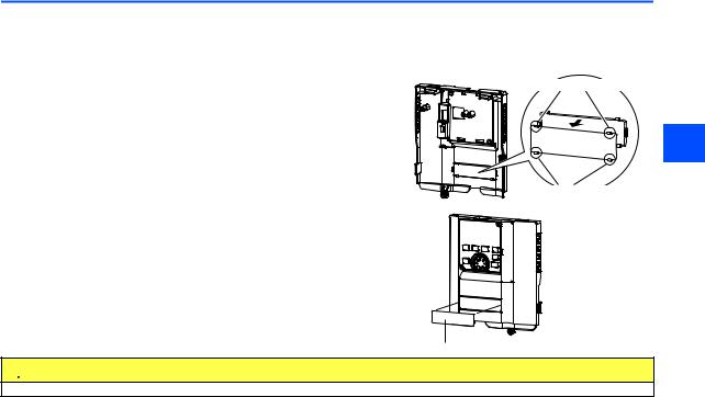
Installing the communication option LED display cover
(1)Remove the inverter front cover. (Refer to Chapter 2 of the Instruction Manual (Detailed) of the inverter for instructions for removing the front cover.)
Follow instructions for mounting the communication option LED display cover to the inverter front cover.
(2)Cut off the tabs on the rear of the inverter front cover with nipper, etc. and
remove the separate part to make space for fitting the LED display cover.
Cut off the tabs with a nipper, etc.
2
Cut off the tabs with a nipper, etc.
(3) Fit the communication option LED display cover to the front side of the front cover. Align the LED display cover with the LED position on the circuit board of the option. Push the LED display cover until it is fixed with the clips.
Communication option LED display cover
 CAUTION
Take care not to hurt your hand and such with portions left by cutting tabs of the rear of the front cover.
INSTALLATION |
|
11 |
|
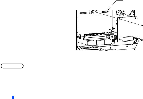
Installing the option
(1)Insert two spacers into the mounting holes that will not be filled with mounting screws (see the diagrams on the next page to identify the holes).
(2)Fit the board mounted option connector on this product to the guide of the option connector on the inverter and insert the plug-in option as far as it goes. (Select option connector 1 on the inverter.)
(3)Fasten the earth plate to the inverter using the one mounting screw through the hole on the left side (see the diagrams on the next page to identify the hole) (tightening torque 0.33 N·m to 0.40 N·m).
(4)Fasten this product to the inverter using the one mounting screw through the hole on the left side. Fasten the earth plate and this product to the inverter using the last screw through the hole on the right side of the earth plate and this product (tightening torque 0.33 N·m to 0.40 N·m). If the screw holes do not line up, the connector may not be inserted deep enough. Check the connector.
Option connector on the inverter
 Spacer
Spacer
 Earth plate
Example: Attachment of this product to connector 1 on the FR-A800
 NOTE
NOTE
•When a communication option is installed to the FR-A800-E/FR-F800-E series inverter, use the earthing (grounding) cable supplied with the inverter instead of the earth plate supplied with the communication option. (For details of the installation method, refer to the Instruction Manual of the inverter.)
12 INSTALLATION

Connector 3 |
2 |
Do not insert the plug-in option to the connector 2 or 3. |
|
|
Mounting screw |
|
Spacer |
Connector 2 |
Connector 1 |
|
Spacer |
|
Mounting screw |
Mounting screw |
Earth plate |
|
Insertion positions for screws and spacers
INSTALLATION |
|
13 |
|

NOTE
•When installing/removing the plug-in option, hold the sides of the option. Do not press on the parts on the option circuit board. Stress applied to the parts by pressing, etc. may cause a failure.
•Be careful not to drop mounting screws during the installation or removal of the plug-in option.
•Attach this product to option connector 1 on the inverter. If it is attached to option connector 2 or 3, the protective function (E.2 or E.3) is activated and the inverter will not operate.
Even if this product is attached to option connector 1, when the inverter cannot recognize that the option is mounted due to improper installation, etc., the protective function (E.1) is activated.
Mounted position |
Fault indication |
|
|
Option connector 1
Option connector 2
Option connector 3
•When removing the plug-in option, remove the two screws on either side, and then pull it straight out. Pressure applied to the option connector and to the option board may break the option.
•Always attach the earth plate because a malfunction due to noises may occur without it.
14 INSTALLATION

2.3Setting of the terminating resistor selection switch
Always set the terminating resistor selection switch (refer to page 7) or connect the one-touch connector plug with terminating resistor (refer to page 21) to the inverter that is the end station (FR-A8NC) in advance.
The following table lists the specifications of the terminating resistor selection switch. (In the initial setting, no terminating resistor is set (1: OFF and 2: OFF).)
Setting
ON |
2 |
1 |
|
ON |
2 |
1 |
|
ON |
2 |
1 |
|
ON |
2 |
1 |
1 |
2 |
Description |
|
|
OFF |
OFF |
Without terminating resistor (initial setting) |
|
|
|
|
|
|
|
ON |
OFF |
Do not use. |
|
2 |
OFF |
ON |
130 (resistance value with the CC-Link Ver. 1.00 dedicated high performance cable) |
|
|
ON |
ON |
110 |
|
|
|
|
|
|
|
INSTALLATION |
|
15 |
|

3 WIRING
3.1Connecting the CC-Link dedicated cable
3.1.1Fabricating the connection cable
In the CC-Link system, use CC-Link dedicated cables. If the cable used is other than the CC-Link dedicated cable, the performance of the CC-Link system is not guaranteed. Refer to the following list for CC-Link dedicated cables that can be used with one-touch connector plugs.
• CC-Link dedicated cable (as of October 2018) (The product may be changed without notice.)
Model |
Manufacturer |
FANC-110SBH |
Kuramo Electric Co., Ltd. |
|
|
CS-110 |
Dyden Corporation |
|
|
FA-CBL200PSBH |
Mitsubishi Electric Engineering Co., Ltd. |
|
|
NOTE
•For the specifications of the CC-Link dedicated cable, refer to the website of the CC-Link Partner Association. (Website of the CC-Link Partner Association http://www.cc-link.org/)
16 WIRING
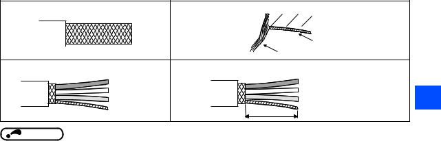
(1) Cable-end treatment
Apply the following treatment at wire end of the CC-Link dedicated cable that is inserted to a CC-Link communication onetouch connector plug (accessory).
1. Cut the sheath |
2. Separate shielding wires from the drain wire. Cut the shielding wires. |
|||||
|
|
|
|
|
|
|
|
|
|
|
|
|
|
|
|
|
|
|
|
|
|
|
|
|
|
|
|
|
Drain wire |
|
|
Shielding wires |
|
3. Cut the aluminum tape and braid. |
4. Straighten the drain wire and twist it from the root. |
|
|
(Twist seven times or more per 3 cm.) |
|
DA (Blue) |
DA (Blue) |
|
DB (White) |
DB (White) |
3 |
DG (Yellow) |
DG (Yellow) |
Drain wire |
3 cm |
Drain wire (AWG20) |
|
|
NOTE
•Where possible, round the cable tip that is cut off with a tool such as nippers. If the cable is not rounded, it may get caught in the middle of a plug, without fully entering into the plug.
•If required, apply an insulation treatment to the shielding wire area where it is not covered by the CC-Link communication one-touch connector plug.
WIRING |
|
17 |
|

(2) Plug cover check
Check that the plug cover is snapped into the CC-Link communication one-touch connector plug.
Plug
Plug cover
NOTE
•Do not push the plug cover onto the plug before inserting a cable. Once crimped, the plug cover cannot be reused.
•CC-Link communication one-touch connector plug (as of October 2018) (The product may be changed without notice.) If purchasing a CC-Link communication one-touch connector plug separately, refer to the plugs in the following list.
Model |
Manufacturer |
A6CON-L5P |
Mitsubishi Electric Corporation |
|
|
35505-6000-B0M GF |
3M Japan Limited |
|
|
18 WIRING

(3) Cable insertion
Lift up the tail of the plug cover. Fully insert each signal cable into the CC-Link communication one-touch connector plug as shown in the right figure.
NOTE
5 4 3 2 1
Signal name
DA (Blue) |
|
|
DB (White) |
3 |
|
DG (Yellow) |
||
Not used |
||
|
||
SLD (Drain wire) |
|
•Insert the cable fully. Failure to do so may cause a crimping failure.
•A cable sometimes comes out of the head of the cover. In that case, pull the cable a little so that the cable stays under the plug cover.
(4)Crimping the plug cover
Push the plug cover onto the plug with a tool such as pliers. After crimping, check that the plug cover is securely snapped into the plug as shown in the right figure.
NOTE
•Misaligned latches between the plug cover and the plug may keep the cover lifted. The plug cover is not sufficiently crimped in this condition. Push the plug cover until it snaps into the plug.
WIRING |
|
19 |
|
3.1.2Connection to the connector
Connect the CC-Link dedicated cable to the CC-Link communication connector.
CC-Link communication connector
CC-Link  dedicated cable
NOTE
•When wiring cables to the inverter's RS-485 terminals while a plug-in option is mounted, take caution not to let the cables touch the circuit board of the option or of the inverter. Otherwise, electromagnetic noises may cause malfunctions.
 Caution
Take caution not to subject the cables to stress.
After wiring, wire offcuts must not be left in the inverter. Wire offcuts can cause an alarm, failure or malfunction.
20 WIRING

3.1.3Unit replacement while online
Connect an online communication connector to the CC-Link communication connector. The online communication connector enables a unit replacement without interrupting the communication. Always connect the online communication connector to connector 1 (front side) of the CC-Link communication connector. (Do not connect it to connector 2 (back side) of the CC-Link communication connector. Doing so will cause a failure or breakage of the inverter and the connectors.)
Also connect a one-touch connector plug with terminating resistor to the CC-Link communication connector of FR-A8NC at the end.
(A replacement while online is not available for the units, which are using the built-in terminating resistor selection switches. (Refer to page 15.))
|
At the end |
Connector 1 |
3 |
Connector 2 |
|
Online communication connector
One-touch connector plug with terminating resistor
WIRING |
|
21 |
|

Use the following online communication connector and one-touch connector plug with terminating resistor.
• Online communication connector (as of October 2018) (The product may be changed without notice.)
Model |
Manufacturer |
35715-L010-B00 AK |
3M Japan Limited |
|
|
• One-touch connector plug with terminating resistor (as of October 2018) (The product may be changed without notice.)
Model |
Manufacturer |
A6CON-TR11N |
Mitsubishi Electric Corporation |
|
|
NOTE
•Do not use the online communication connector A6CON-LJ5P (Mitsubishi Electric Corporation) and 35720-L200-B00 AK (3M Japan Limited) for this product. Doing so will cause a failure or breakage of the inverter and the connectors.
22 WIRING
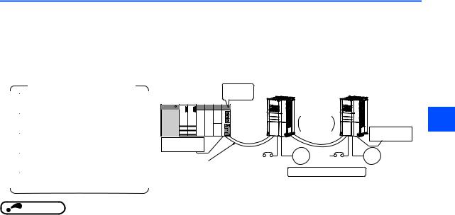
3.2System configuration example
(1)Programmable controller side
Load the "RJ61BT11", "QJ61BT11N", "L26CPU-BT", "L26CPU-PBT", "LJ61BT11", "A1SJ61QBT11" or "A1SJ61BT11" type CC-Link system master/local module on the main or extension base unit having the programmable controller CPU used as the master station.
(2)Inverter side
Mount the plug-in option (FR-A8NC) on the inverter.
(3)Connect the master station of the CC-Link programmable controller unit to the CC-Link communication connector of FRA8NC with the CC-Link dedicated cable.
Manual of the CC-Link master station
RJ61BT11 type
CC-Link System Master/Local Module User's Manual ...SH-081270ENG QJ61BT11N type
CC-Link System Master/Local Module User's Manual ...SH-080394E
L26CPU-BT type/L26CPU-PBT type/LJ61BT11 type CC-Link System Master/Local Module
User's Manual ...SH-080895ENG A1SJ61QBT11 type
CC-Link System Master/Local Module User's Manual ...IB-66722 A1SJ61BT11 type
CC-Link System Master/Local Module User's Manual ...IB-66721
|
Master |
Inverter |
Inverter |
|
station |
Up to 42 |
|
|
QJ61BT11N, |
units can be |
|
|
connected |
3 |
|
|
etc. |
when only |
|
|
|
||
|
|
inverters are |
|
|
|
connected |
Terminating |
Terminating |
|
|
resistor |
resistor |
Power |
Power |
|
|
supply |
Motor supply |
Motor |
CC-Link dedicated cable |
Remote device station |
||
|
|
||
NOTE
•When the CPU has automatic refresh function (example: QnA series CPU)
When the END instruction is executed by the programmable controller CPU, the buffer memory is automatically refreshed to enable communication with a remote device.
•When the CPU does not have automatic refresh function (example: AnA series CPU)
Sequence ladder logic is configured to perform direct communication with the buffer memory of the master station and to enable communication with a remote device
WIRING |
|
23 |
|

3.3Connection of several inverters
An inverter can join the link system as a CC-Link remote device station, and such device stations can be controlled and monitored with a user program of a programmable controller. These devices can be useful components of an automated factory.
Connect shielding wires of the CC-Link dedicated cable to "SLD" of each unit.
Master module |
FR-A8NC 2 |
FR-A8NC |
|
|||
Terminating |
DA |
Blue |
DA |
Blue |
DA |
Terminating resistor |
White |
White |
|||||
resistor 1 |
DB |
|
DB |
|
DB |
selection switch 3 |
|
DG Yellow |
DG Yellow |
DG |
|
||
|
SLD |
Shielded |
SLD |
Shielded |
SLD |
|
|
|
|
|
|
||
|
|
twisted cable |
|
twisted cable |
|
|
Use the terminating resistors supplied with the programmable controller.
Set "1" and "2" of the terminating resistor selection switch to OFF (without terminating resistor) in the middle units. (Refer to page 15.)Set the terminating resistor selection switch. (Refer to page 15.)
Do not use the built-in terminating resistor selection switch when using a one-touch connecter plug with terminating resistor. (1-OFF, 2- OFF) (Refer to page 21 for the details of the one-touch connector plug with terminating resistor.)
•Maximum number of units connected to one master station (CC-Link Ver.1.10) 42 units (when connections are inverters only)
24 WIRING

•Maximum number of units connected to one master station (CC-Link Ver.2.00) 42 units (when connections are inverter only)
|
|
|
|
|
|
If any other units are included, the number of stations occupied depends on the unit and therefore the following |
|
|
|
|
conditions must be satisfied: |
|
||
• |
{(a + a2 + a4 + a8) + (b + b2 + b4 + b8) 2 + (c + c2 + c4 + c8) 3 + (d + d2 + d4 + d8) 4} 64 |
|
||
• |
{(a 32 + a2 32 + a4 64 + a8 128) + (b 64 + b2 96 + b4 192 + b8 384) + (c 96 + c2 160 + c4 320 + |
|
||
|
c8 640) + (d 128 + d2 224 + d4 448 + d8 896)} 8192 |
|
||
• |
{(a 4 + a2 8 + a4 16 + a8 32) + (b 8 + b2 16 + b4 32 + b8 64) + (c 12 + c2 24 + c4 48 + c8 96) + |
|
||
|
(d 16 + d2 32 + d4 64 + d8 128)} 2048 |
|
||
|
a: Number of single setting devices occupying one station |
|
||
|
b: Number of single setting devices occupying two stations |
|
||
|
c: Number of single setting devices occupying three stations |
|
||
|
d: Number of single setting devices occupying four stations |
3 |
||
|
a2: Number of double setting devices occupying one station |
|||
b2: Number of double setting devices occupying two stations c2: Number of double setting devices occupying three stations d2: Number of double setting devices occupying four stations a4: Number of quadruple setting devices occupying one station b4: Number of quadruple setting devices occupying two stations
c4: Number of quadruple setting devices occupying three stations d4: Number of quadruple setting devices occupying four stations a8: Number of octuple setting devices occupying one station
b8: Number of octuple setting devices occupying two stations c8: Number of octuple setting devices occupying three stations d8: Number of octuple setting devices occupying four stations
•16 A + 54 B + 88 C 2304
A:Numbers of remote I/O 64
B:Number of remote device stations 42
C:Number of local and intelligent device stations 26
|
|
|
|
WIRING |
|
25 |
|
|
|||

4 INVERTER SETTING
4.1Parameter list
The following parameters are used for the plug-in option (FR-A8NC).
Set the values according to need. For the parameter details, which depend on the applicable model of the inverter, refer to the Instruction Manual (Detailed) of the inverter.
|
|
|
|
|
|
Minimum |
Initial |
Refer to |
|
Pr. |
Pr. group |
Name |
Setting range |
setting |
|||||
value |
page |
||||||||
|
|
|
|
|
|
increments |
|||
|
|
|
|
|
|
|
|
||
79 |
D000 |
Operation mode selection |
0 to 4, 6, 7 |
1 |
0 |
28 |
|||
|
|
|
|
|
|
|
|||
313 |
M410 |
DO0 output selection |
|
|
|
|
|||
|
|
|
|
|
The setting range depends on the |
|
|
|
|
314 |
M411 |
DO1 output selection |
1 |
9999 |
59 |
||||
inverter. |
|||||||||
|
|
|
|
|
|
|
|
||
315 |
M412 |
DO2 output selection |
|
|
|
|
|||
|
|
|
|
|
|
|
|
|
|
338 |
D010 |
Communication operation command |
0, 1 |
1 |
0 |
|
|||
source |
|||||||||
|
|
|
|
|
|
|
|
||
|
|
|
|
|
|
|
|||
339 |
D011 |
Communication speed command source |
0, 1, 2 |
1 |
0 |
|
|||
|
|
|
|
|
|
|
|||
340 |
D001 |
Communication startup mode selection |
0, 1, 2, 10, 12 |
1 |
0 |
28 |
|||
|
|
|
|
|
|
|
|||
342 |
N001 |
Communication EEPROM write selection |
0, 1 |
1 |
0 |
|
|||
|
|
|
|
|
|
|
|
|
|
349 |
N010 |
Communication reset selection/Ready bit |
0, 1, 100, 101 |
1 |
0 |
38 |
|||
status selection |
|||||||||
|
|
|
|
|
|
|
|
||
|
|
|
|
|
|
|
|
|
|
500 |
N011 |
Communication error execution waiting |
0 to 999.8 s |
0.1 s |
0 s |
31 |
|||
time |
|||||||||
|
|
|
|
|
|
|
|
||
|
|
|
|
|
|
|
|
|
|
501 |
N012 |
Communication error occurrence count |
0 |
1 |
0 |
32 |
|||
display |
|||||||||
|
|
|
|
|
|
|
|
||
|
|
|
|
|
|
|
|
|
|
26 |
|
|
INVERTER SETTING |
|
|
|
|
||
|
|
|
|
|
|
||||
|
|
|
|
|
Minimum |
Initial |
Refer to |
|
|
Pr. |
|
Pr. group |
Name |
Setting range |
setting |
|
|
||
|
value |
page |
|
|
|||||
|
|
|
|
|
increments |
|
|
||
|
|
|
|
|
|
|
|
|
|
502 |
|
N013 |
Stop mode selection at communication |
0 to 4, 11, 12 |
1 |
0 |
32 |
|
|
|
error |
|
|
||||||
|
|
|
|
|
|
|
|
|
|
|
|
|
|
|
|
|
|
|
|
541 |
|
N100 |
Frequency command sign selection |
0, 1 |
1 |
0 |
41 |
|
|
|
|
|
|
|
|
|
|
|
|
542 , |
N101 , , |
Communication station number (CC-Link) |
1 to 64 |
1 |
1 |
39 |
|
|
|
, |
|
|
|
|
|||||
|
|
|
|
|
|
|
|
||
543 , |
N102 , , |
Baud rate selection (CC-Link) |
0 to 4 |
1 |
0 |
40 |
|
|
|
, |
|
|
|
|
|||||
|
|
|
|
|
|
|
|
||
|
, |
|
|
0, 1, 12, 14, 18, 24, 28, 100, 112, |
|
|
|
|
|
544 |
N103 , |
CC-Link extended setting |
114, 118, 128 |
1 |
0 |
46 |
|
|
|
|
|
|
|
||||||
|
|
|
|
|
|
|
|
||
|
|
|
|
|
|
|
|
|
|
550 |
|
D012 |
NET mode operation command source |
0, 1, 9999 |
1 |
9999 |
|
|
|
|
selection |
|
|
||||||
|
|
|
|
|
|
|
|
|
|
|
|
|
|
|
|
|
|
|
|
|
|
|
Operation frequency during |
|
|
|
|
|
|
779 |
|
N014 |
0 to 590 Hz, 9999 |
0.01 Hz |
9999 |
32 |
|
4 |
|
|
communication error |
|
|||||||
|
|
|
|||||||
|
|
|
|
|
|
|
|
|
|
|
|
|
|
|
|
|
|
|
|
804 |
|
D400 |
Torque command source selection |
0, 1, 3 to 6 |
1 |
0 |
73 |
|
|
|
|
||||||||
|
|
|
|
|
|
|
|
|
|
810 |
|
H700 |
Torque limit input method selection |
0 to 2 |
1 |
0 |
73 |
|
|
|
|
|
|
|
|
|
|
|
|
Parameters which can be displayed when the plug-in option (FR-A8NC) is mounted.The setting is reflected after inverter reset or at the next power-on.
"L.ERR" LED flickers if the setting is changed. If the inverter is reset, the setting is reflected and the LED turns off.Refer to the Instruction Manual (Detailed) of the inverter for the parameter details.
The setting is available only for the FR-A800 series.
The settings of Pr.544="24, 28, or 128" and Pr.810="2" can be set only when the inverter supports this function. (Refer to page 73.)
INVERTER SETTING |
|
27 |
|

4.2Operation mode setting
4.2.1Operation mode switching and communication startup mode (Pr.79, Pr.340)
Operation mode switching conditions
Check the following before switching the operation mode.
• The inverter is at a stop;
• Both the STF and STR signals are off; and
• The Pr.79 Operation mode selection setting is correct. (Check the setting on the operation panel of the inverter.)
Operation mode selection at power ON and at restoration from instantaneous power failure
The operation mode at power ON and at restoration from instantaneous power failure can be selected.
Set a value other than "0" in Pr.340 Communication startup mode selection to select the network operation mode. After started in network operation mode, parameter write from the network is enabled.
(Refer to page 85 for a program example for parameter write.)
NOTE
•Change of the Pr.340 setting is valid when powering on or resetting the inverter.
•Pr.340 can be changed with the operation panel independently of the operation mode.
•Ensure that the communication setting of the inverter is completed before setting Pr.340 "0".
•Refer to the Instruction Manual (Detailed) of the inverter for details of Pr.79, Pr.340.
28 INVERTER SETTING
Pr.340 |
Pr.79 |
Operation mode at power ON or power |
Operation mode switchover |
|
|
|
setting |
setting |
restoration |
|
|
||
|
|
|
||||
|
0 (initial |
External operation mode |
Switching among the External, PU, and NET operation |
|
|
|
|
value) |
mode is enabled. , |
|
|
||
|
|
|
|
|||
|
|
|
|
|
|
|
|
1 |
|
PU operation mode |
PU operation mode fixed |
|
|
|
|
|
|
|
|
|
|
|
|
|
Switching between the External and Net operation mode is |
|
|
|
2 |
|
External operation mode |
enabled. |
|
|
0 |
|
|
|
Switching to the PU operation mode is disallowed. |
|
|
|
|
|
|
|
|
|
(initial |
3, 4 |
|
External/PU combined operation mode |
Operation mode switching is disallowed. |
|
|
value) |
|
|
|
|
|
|
6 |
|
External operation mode |
Switching among the External, PU, and NET operation |
|
|
|
|
|
|
|
|||
|
|
mode is enabled while running. |
|
|
||
|
|
|
|
|
|
|
|
|
|
|
|
|
|
|
|
|
X12 (MRS) signal ON: external operation mode |
Switching among the External, PU, and NET operation |
|
|
|
|
|
mode is enabled. , |
|
|
|
|
7 |
|
|
|
|
|
|
|
|
|
|
|
|
|
|
X12 (MRS) signal OFF: external operation mode |
External operation mode fixed (Forcibly switched to |
|
|
|
|
|
|
|
|
||
|
|
|
4 |
|||
|
|
|
External operation mode.) |
|
||
|
|
|
|
|
||
|
|
|
|
|
|
|
|
0 |
|
NET operation mode |
|
|
|
|
1 |
|
PU operation mode |
|
|
|
|
|
|
|
|
|
|
|
2 |
|
NET operation mode |
|
|
|
1, 2 |
3, 4 |
|
External/PU combined operation mode |
Same as when Pr.340 = "0" |
|
|
|
|
|
|
|
|
|
|
6 |
|
NET operation mode |
|
|
|
|
7 |
|
X12 (MRS) signal ON........ NET operation mode |
|
|
|
|
|
X12 (MRS) signal OFF........external operation mode |
|
|
|
|
|
|
|
|
|
|
|
|
|
|
|
|
|
|
INVERTER SETTING |
|
29 |
|
Loading...