


F920GOT-BBD-K-E
Table of contents
 Loading...
F920GOT-BBD5-K-E
F920GOT-BBD-K-E
Installation Manual
JY997D02201G
This manual contains text, diagrams and explanations which will guide the reader in the correct installation, safe use and
operation of the F920GOT-BBD5-K-E, F920GOT-BBD-K-E and should be read and understood before attempting to
install or use the unit. Further information can be found in the associated manuals list below.
Specifications are subject to change without notice
Guidelines for the Safety of the User and Protection of the F920GOT-BBD5-K-E,
F920GOT-BBD-K-E
This manual has been written to be used by trained and competent personnel. The definition of such a person or persons
is as follows:
a) Any engineer using the product associated with this manual, should be of a competent nature, trained and
qualified to the local and national standards. These engineers should be fully aware of all aspects of safety with
regards to automated equipment.
b) Any commissioning or service engineer must be of a competent nature, trained and qualified to the local and
national standards.
c) All operators of the completed equipment (see note) should be trained to use that product in a safe manner in
compliance to established safety practices.
Note:
The term ‘completed equipment’ refers to a third party constructed device which contains or uses the product
associated with this manual.
Note’s on the Symbols Used in this Manual
At various times through out this manual certain symbols will be used to highlight points of information which are intended
to ensure the users personal safety and protect the integrity of equipment.
1) Indicates that the identified danger
WILL
cause physical and proper ty damage.
2) Indicates that the identified danger could
POSSIBLY
cause physical and proper ty damage.
• Under no circumstances will Mitsubishi Electric be liable or responsible for any consequential damage that may arise
as a result of the installation or use of this equipment.
• All examples and diagrams shown in this manual are intended only as an aid to understanding the text, not to
guarantee operation. Mitsubishi Electric will accept no responsibility for actual use of the product based on these
illustrative examples.
• Please contact a Mitsubishi Electric distributor for more information concerning applications in life critical situations
or high reliability.
Associated Manuals
~
Necessary manual
|
Either manual is necessary.
Refer to the manual of the connected programmable controller for further details concerning that unit.
Manual Name Manual Number Description
|
F920GOT-BBD5-K-E,
F920GOT-BBD-K-E
Installation Manual
JY997D02201
(This manual)
Describes the hardware such as specifications, wiring and
installation of the F920GOT-BBD5-K-E and F920GOT-BBD-
K-E.
~
GOT-F900
OPERATION MANUAL
(describes GT Designer2)
JY997D09101
(separate volume)
Describes the operation and use of the GOT-F900 Series
graphic operation terminals and GT Designer2.
~
GOT-F900 Series
Operation Manual
JY992D94701
(separate volume)
Describes the operation and use of the GOT-F900 Series
graphic operation terminals, GT Designer and FX-PCS-DU/
WIN-E.
~
GOT-F900 Series
Hardware Manual
(connection diagram)
JY992D94801
(separate volume)
Describes wiring and installation of the GOT-F900 Series
graphic operation terminals.
|
SW
D5C-GOTR-PACK
Operating Manual
(included with screen
creation software)
Describes the operating procedures of the screen creation
software. (See the HELP file in the software.)
|
GT Designer2 Version 1
Operating Manual
(PDF files on CD-ROM
included with screen
creation software)
Describes the operation method of GT Designer2
(SW
D5C-GTD2-J), data transfer to the GOT-900 Series,
etc.
|
GT Designer2 Version 1
Reference Manual
(PDF files on CD-ROM
included with screen
creation software)
Describes the specifications, contents of setting, etc. of
each object function used in GT Designer2 (SW
D5C-
GTD2-J).
|
FX-PCS-DU/WIN-E
SOFTWARE MANUAL
JY992D68301
(included with screen
creation software)
Describes the operation of FX-PCS-DU/WIN-E screen
creation software.
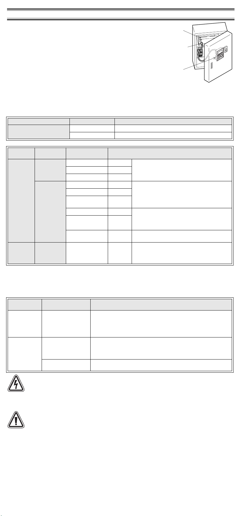
PLC
Programming
port
GOT
35.5(1.40")
5(0.20")
106(4.17")
134(5.28")
a)
b)
d)
c)
Front panel
Rear panel (with mounting bracket and tightening bolt)
1. Introduction
1) The F920GOT-BBD5-K-E and F920GOT-BBD-K-E (hereafter called “GOT”)
are to be mounted on the face of a control or operations panel, and
connected to the programming port (CPU port) of a PLC.
2) Various devices can be monitored and PLC data changed through the
screens in the GOT.
3) Using PLC programming software, FX Series PLC user programming can be
uploaded, downloaded and monitored via the GOT.
4) The F920GOT-BBD5-K-E is driven by 5V DC power supply (from the PLC
through a communication cable). The F920GOT-BBD-K-E is driven by a 24V
DC power supply.
5) The F920GOT-BBD5-K-E can be connected to the FX, A, QnA and Q Series
PLC.
The F920GOT-BBD-K-E can be connected to the FX, A, QnA and Q Series
PLC, PLC manufactured by another company and micro computer board.
For further details concerning applicable PLCs and connections to the PLC, refer to the GOT-F900 Series Hardware
Manual (Connection Diagram) offered as a separate volume.
1.1 Product Lists
GOT Main Unit
Optional communication cable
• In addition to the connections shown above, the F920GOT-BBD5-K-E can be connected to the A, QnA and Q Series
PLC, and the F920GOT-BBD-K-E can be connected to via computer link to a PLC manufactured by Mitsubishi, PLC
manufactured by another manufacturers and micro computer board.
For further details concerning connectable equipment and communication cables, refer to the GOT-F900 Series
Hardware Manual [Connection] offered as a separate volume.
Optional screen creation software
Caution
During abnormal communication (including cable breakage) when monitoring within the GOT,
communication between the GOT and programmable controller CPU is interrupted and it is impossible to
operate keys or devices in the PLC via the GOT.
Communication and operation resumes when the GOT system is correctly configured.
DO NOT configure the emergency stop or safety features through the GOT, and be sure that there will be
no adverse consequences in the event of a GOT - PLC communications malfunction.
Note
• Do not lay signal cables near high voltage power cables or allow them to share the same trunking duct.
Otherwise effects of noise or surge induction are likely to occur. Keep a safe distance of more than 100
mm away from these wires.
• Operate switches on the panel by hand.
DO NOT use excessive force, or attempt to operate them with hard or pointed objects.
The tip of a screw driver, pen or similar objects for example may break the screen.
Connectable PLC units differ for the F920GOT-BBD5-K-E and the F920GOT-BBD-K-E.
Further information can be found in GOT-F900 series Hardware Manual [Connection].
Product Name Model Name Specifications
Graphic Operation Terminal
F920GOT-BBD5-K-E Graphic operation ter minal main unit
F920GOT-BBD-K-E Graphic operation terminal main unit
Product
Name
Classification Model Name Specifications
PLC
connection
cable
F920GOT-
BBD5-K-E
FX-50DU-CAB0 3m (9’10”) Communication cable (GOT
↔
CPU port in FX
0S
,
FX
1S
, FX
0N
, FX
1N
, FX
2N
or FX
2NC
series PLC)
Cable length is 3m (9' 10").
Use FX-50DU-CAB0/EN for compliance to EC EMC.
FX-50DU-CAB0/EN 3m (9’10”)
FX-50DU-CAB0-1M 1m (3’3”)
F920GOT-
BBD-K-E
FX-50DU-CAB0 3m (9’10”) Communication cable (GOT
↔
CPU port in FX
0S
,
FX
1S
, FX
0N
, FX
1N
, FX
2N
or FX
2NC
series PLC)
(**M is cable length 1M:1m(3’3”), 10M:10m(32’9”),
20M:20m(65’7”), 30M:30m(98’5”).
Use FX-50DU-CAB0/EN for compliance to EC EMC.
FX-50DU-CAB0/EN 3m (9’10”)
FX-50DU-CAB0-**M
Described
on right
FX-40U-CAB 3m (9’10”) Communication cable (GOT
↔
CPU port in A, QnA
series PLC)
(**M is cable length 10M:10m(32’9”),
20M:20m(65’7”), 30M:30m(98’5”).
FX-40DU-CAB0-**M
Described
on right
QC30R2 3m (9’10”)
Communication cable (GOT
↔
CPU port in Q series
PLC)
Screen data
transfer
cable
F920GOT-
BBD5-K-E
and F920GOT-
BBD-K-E
FX-232CAB-1 3m (9’10”)
Data exchange cable (GOT
↔
Personal computer
<9-pin D-sub>)
Product
Name
Model Name Specifications
For F920GOT-
BBD5-K-E and
F920GOT-BBD-
K-E
GT Designer 2
SW
D5C-GTD2-E (
indicates the version.)
Software for GOT-F900 and GOT-A900 Series (for Windows)
In F920GOT-BBD5-K-E, SW1D5C-GTD2-E Version 1.00A or later is
available.
In F920GOT-BBD-K-E, SW1D5C-GTD2-E Version 1.02C or later is
available.
F920GOT-BBD5-
K-E
GT Designer
SW
D5C-GOTR-
PACKE (
indicates the
version .)
Software for GOT-F900 and GOT-A900 Series (for Windows)
SW5D5C-GOTR-PACK-E SW5-26C version (Version 5.26C) or later
FX-PCS-DU/WIN-E
Software for GOT-F900 Series (for Windows)
SW0PC-FXDU/WIN-E Version 2.70 or later
PLC
Programming
port
GOT
35.5(1.40")
5(0.20")
106(4.17")
134(5.28")
a)
b)
d)
c)
Front panel
Rear panel (with mounting bracket and tightening bolt)
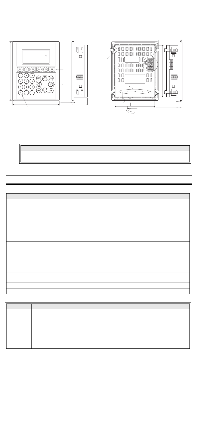
1.2 Dimensions and Each Part Name [Both F920GOT-BBD5-K-E and F920GOT-BBD-K-E
(Power terminals is excluded).]
Dimensions: mm (inches) Mass (Weight): 0.3 kg (0.66 lbs)
Accessory: Mounting brackets, Tightening bolt (M4, 4 bolts), Packing seal for dust and water resistance
1) Front panel
a) Display b) Function keys c) Cursor keys d) 0 to 9 keys
2) Rear panel
e) Mounting bracket and tightening bolt (accessory)
f) Power terminals (Not provided for the F920GOT-BBD5-K-E)
g) Communication ports
h) Communication cable (optional)
i) Packing seal (accessory)
2. Specifications
2.1 General Specifications (F920GOT-BBD5-K-E and F920GOT-BBD-K-E)
2.2 Power Supply Specifications
Port Description
COM0 RS-422 RS-422 port for connecting PLC (FX, A, QnA) <9-pin D-sub>
COM1 RS-232C RS-232C port for connecting a personal computer or PLC (Q) <9-pin D-sub>
Item Specifications
Operating Temperature 0 ~ 50 °C (32 ~ 122 °F)
Storage Temperature -20 ~ 60 °C (-4 ~ 140 °F)
Humidity 35 ~ 85% Relative Humidity, No condensation
Operating atmosphere
Must be free of lamp black, corrosive gas, flammable gas, or excessive amount of
electroconductive dust par ticles and must be no direct sunlight. (Same as for saving)
Vibration Resistance
- intermittent vibration
10 ~ 57 Hz: 0.075 mm Half Amplitude
57 ~ 150 Hz: 9.8 m/s
2
Acceleration
Sweep Count for X, Y, Z: 10 times (80 min. in each direction)
Vibration Resistance
- Continuous vibration
10 ~ 57 Hz: 0.035 mm Half Amplitude
57 ~ 150 Hz: 4.9 m/s
2
Acceleration
Sweep Count for X, Y, Z: 10 times (80 min in each direction)
Shock Resistance
147m/s
2
Acceleration,
3 times in each direction X, Y, and Z
Noise Immunity 1000 Vp-p, 1
µ
second, 30 ~ 100 Hz, tested by noise simulator
Dielectric Withstand
Vo lt ag e
500 V AC > 1 min, tested between power terminals and ground
Insulation Resistance 5 M
Ω
> at 500 V DC, tested between power terminals and ground
Protection IP65f level (Front panel only)
Model Name Specifications
F920GOT-
BBD5-K-E
Supply voltage : 5V DC ±5% (supplied from PLC through communication cable)
Current consumption : 220mA/5V DC while backlight is ON, 180mA/5V DC while backlight is OFF
F920GOT-
BBD-K-E
Supply voltage : 24V DC+10%-15% (externally supplied through power terminals)
Power ripple : 220 mV or less
Current consumption : 80mA/24V DC while backlight is ON, 70mA/24V DC while backlight is OFF
Fuse : Built-in (It cannot be replaced.)
Allowable instantaneous power interr uption:
Less than 5 ms (Continuous operation is assured.)
Grounding : Grounding resistance: 100
Ω
or less
35.5(1.40")
5(0.20")
106(4.17")
134(5.28")
a)
b)
d)
c)
118(4.65")
90(3.54")
5(0.20") or less
e)
g)
i)
h)
COM1 RS232C
COM0 RS422
f)
Front panel
Rear panel (with mounting bracket and tightening bolt)
Loading...