


 Loading...
PROGRAMMABLE LOGIC CONTROLLER
MODEL
FX3GE
QUICK START MANUAL
Mitsubishi Electric Automation, Inc.

FX3GE QUICK START MANUAL |
|
|
1. INTRODUCTION................................................................. |
3 |
|
1.1 CAUTION........................................................................... |
3 |
|
1.2 INCLUDED ITEMS............................................................. |
3 |
|
1.3 FRONT PANEL................................................................... |
3 |
|
2. DIMENSIONS....................................................................... |
4 |
|
3. INSTALLATION................................................................... |
4 |
|
3.1 |
SPECIFICATIONS............................................................. |
5 |
3.2 |
MOUNTING INSTRUCTIONS........................................... |
6 |
4. SPECIFICATIONS AND WIRING.................................. |
7 |
|
4.1 |
WIRING.............................................................................. |
7 |
4.2 |
GROUNDING.................................................................... |
8 |
4.3 |
POWER SUPPLY SPECIFICATIONS AND |
|
|
WIRING DIAGRAM............................................................ |
8 |
4.4 |
INPUT SPECIFICATIONS AND WIRING DIAGRAM......... |
8 |
4.5 |
PULSE CATCH (M8170 TO M8175).................................. |
9 |
4.6 |
PULSE WIDTH/PULSE PERIOD MEASUREMENT |
|
|
SPECIFICATIONS AND WIRING....................................... |
9 |
4.7 |
HIGH SPEED COUNTERS SPECIFICATIONS |
|
|
AND WIRING..................................................................... |
9 |
4.8 |
OUTPUT SPECIFICATIONS AND WIRING..................... |
10 |
5. BUILT-IN ETHERNET...................................................... |
11 |
|
5.1 ETHERNET SPECIFICATIONS AND WIRING................ |
11 |
|
5.2 PARAMETER SETTINGS AND DIAGNOSTICS |
|
|
|
IN GX WORKS2............................................................... |
12 |
6. BUILT-IN ANALOG SPECIFICATIONS |
|
|
AND WIRING...................................................................... |
19 |
|
6.1 ANALOG INPUT TERMINAL BLOCK ............................. |
19 |
|
7. PROGRAMMING USING GX WORKS2.................... |
21 |
|
7.1 |
SYSTEM CONFIGURATION............................................ |
21 |
7.2 |
INSTALLING THE USB DRIVER...................................... |
21 |
7.3 |
INSTALLING GX WORKS2.............................................. |
23 |
7.4 |
STARTING AND EXITING GX WORKS2.......................... |
24 |
7.5 |
USING THE HELP FILES IN GX WORKS2..................... |
24 |
8. OPERATION....................................................................... |
25 |
|
9. MAINTENANCE................................................................ |
27 |
|
10. TROUBLESHOOTING.................................................. |
28 |
|
2
Mitsubishi Electric Automation, Inc.
1. INTRODUCTION
This manual describes the part names, dimensions, mounting, and specifications of the product. Before use, read this manual and the manuals of all relevant products fully to acquire proficiency in
handling and operating the product. Make sure to learn all the product information, safety information, and precautions.
Store this manual in a safe place so that it can be taken out and read whenever necessary. Always forward it to the end user.
Registration
The company name and the product name to be described in this manual are the registered trademarks or trademarks of each company.
Effective August 2013
Specifications are subject to change without notice. © 2013 Mitsubishi Electric Corporation
1.1 CAUTION
Safety Precaution (Read these precautions before use.) This manual classifies the safety precautions into two categories: DANGER and
CAUTION.
 DANGER Indicates that incorrect handling may cause hazardous conditions, resulting in death or severe injury.
 CAUTION Indicates that incorrect handling may cause hazardous conditions, resulting in medium or slight personal injury or physical damage.
Depending on the circumstances, procedures indicated by CAUTION may also cause severe injury. It is important to follow all precautions for personal safety.
DANGER STARTUP AND MAINTENANCE PRECAUTIONS
•Do not touch any terminal while the PLC’s power is on. Doing so may cause electric shock or malfunctions.
•Before cleaning or retightening terminals, cut off all phases of the power supply externally. Failure to do so may cause electric shock.
•Use the battery for memory backup correctly
Use the battery only for the specified purpose.Connect the battery correctly.
Do not charge, disassemble, heat, put in fire, short-circuit, connect reversely, weld, swallow or burn the battery, or apply excessive forces (vibration, impact, drop, etc.) to the battery.
Do not store or use the battery at high temperatures or expose to direct sunlight.
Do not expose to water, bring near fire or touch liquid leakage or other contents directly.
Incorrect handling of the battery may cause heat excessive generation, bursting, ignition, liquid leakage or deformation, and lead to injury, fire or failures and malfunctions of facilities and other equipment.
•Before modifying or disrupting the program in operation or running the PLC, carefully read through this manual to ensure the safety of the operation. An operation error may damage the machinery or cause accidents.
CAUTION STARTUP AND MAINTENANCE PRECAUTIONS
•Do not disassemble or modify the PLC. Doing so may cause fire, equipment failures, or malfunctions.
FX3GE QUICK START MANUAL
•Turn off the power to the PLC before connecting or disconnecting any extension cable. Failure to do so may cause equipment failures or malfunctions.
•Turn off the power to the PLC before attaching or detaching the following devices. Failure to do so may cause equipment failures or malfunctions.
Peripheral devices, display module, battery, and expansion boards
CAUTION DISPOSAL PRECAUTIONS
Please contact a certified electronic waste disposal company for the environmentally safe recycling and disposal of your device. When disposing of batteries, separate them from other waste according to local regulations.
CAUTION TRANSPORT AND STORAGE PRECAUTIONS
•When transporting the FX3GE Series PLC incorporating the optional battery, turn on the PLC before shipment, confirm that the battery mode is set using a parameter and the ALM LED is OFF, and check the battery life. If the PLC is transported with the ALM LED on or the battery exhausted, the battery-backed data may be unstable during transportation.
•The PLC is a precision instrument. During transportation, avoid impacts larger than those specified in this manual. Failure to do so may cause failures in the PLC. After transportation, verify the operations of the PLC.
•When transporting lithium batteries, follow required transportation regulations.
1.2 INCLUDED ITEMS
Check if the following product and items are included in the package:
MAIN UNIT
|
Product |
1 unit |
FX3GE-24MR/ES |
Dust proof protection sheet |
1 sheet |
|
Manual [English version] |
1 manual |
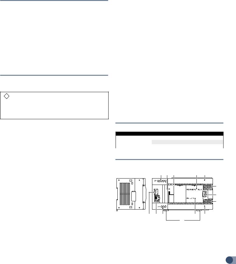
1.3 FRONT PANEL
ν FACTORY DEFAULT CONFIGURATION (STANDARD)
[10] [1] |
[2] |
[3] |
[4] |
|
|
|
[5] |
|
|
|
[6] |
|
|
|
[7] |
[13] [12] [11] |
|
[8] |
[5] |
|
|
[9] |
|
[1]Peripheral device connector cover The peripheral device connector, variable analog potentiometers and RUN/STOP switch are located under this cover.
[2]Terminal names The signal names for power supply, input and output terminals are shown.
[3]Top cover (S) (40 points, 60 points type only) Mount the expansion
board under this cover. |
3 |
Mitsubishi Electric Automation, Inc.

FX3GE QUICK START MANUAL
[4]Terminal block covers The covers can be opened for wiring. Keep the covers closed while the PLC is running (the unit power is on).
[5]Input display LEDs (red) When an input terminal (X000 or more) is turned on, the corresponding LED lights.
[6]Operation status display LEDs The operation status of the PLC can be checked with the LEDs. The LEDs turn off, light and flash according to the following table. For details on the operation status, refer to Section 10.
LED Name |
Display |
Description |
|
Color |
|||
|
|
||
|
|
|
|
POW |
Green |
On while power is on the PLC. |
|
RUN |
Green |
On while the PLC is running. |
|
ERR |
Red |
Flashing when a program error occurs. |
|
|
|||
Lights when a CPU error occurs. |
|||
|
|
||
ALM |
Red |
Lights when the battery voltage drops. |
|
(When the optional battery is used) |
|||
|
|
[7]Output display LEDs (red) When an output terminal (Y000 or more) is turned on, the corresponding LED lights.
[8]Model name (abbreviation) The model name of the main unit is indicated. Check the nameplate on the right side for the model name.
[9]DIN rail mounting hooks The main unit can be installed on DIN46277 rail (35mm (1.38") wide).
[10]Analog input terminal block
[11]Analog output terminal block
[12]10BASE-T/100BASE-TX connector (RJ45)
[13]Ethernet status LEDs
ν WITH TERMINAL COVER OPEN
[1] Peripheral device connector (USB) Connect a programming tool
[1] [2] [3] [4] |
[5] |
[6] |
[7] |
|
|
|
[8] |
|
|
|
[9] |
[5] |
[11] |
[10] |
|
(PC) to program a sequence.
[2]Peripheral device connector (RS-422) Connect a programming tool to program a sequence.
[3]RUN/STOP switch To stop writing (batch) of the sequence program or operation, set the switch to STOP (slide it downward). To start operation (run the machine), set it to RUN (slide it upward).
[4]Variable analog potentiometers Upper side: VR1,
Lower side: VR2 Two variable analog potentiometers are built in. Upper side : VR1, Lower side : VR2
[5]Terminal cover A protective terminal cover
[6]Optional equipment connector Connect the expansion board to the connector.
[7]Power supply terminal, Input (X) terminals Wire switches and sensors to the terminals.
4 [8] Battery connector Connect the optional battery to the connector.
[9]Battery holder This holder accommodates the optional battery.
[10]Power supply terminal, Output (Y) terminals Wire loads (contactors, solenoid valves, etc.) to be driven to the terminals.
[11]Optional equipment connecting screw holes These holes are designed to secure the expansion board and memory cassette with screws.
ν LED STATUS
LED |
LED |
Status |
Description |
|
Display |
Color |
|||
|
|
|||
POW |
Green |
ON |
Power is on |
|
OFF |
Power is off |
|||
|
|
|||
RUN |
Green |
ON |
Running |
|
OFF |
Stopped |
|||
|
|
|||
|
|
ON |
When a CPU error occurs |
|
ERR |
Red |
Flicker |
When a program error occurs |
|
|
|
OFF |
When a normal status |
|
|
|
ON |
When the battery voltage drops |
|
ALM |
Red |
(When the optional battery is installed) |
||
|
||||
|
|
OFF |
When the battery voltage normal status |
|
2. DIMENSIONS |
|
|||
|
|
|
|
|
2-ø4.5 mounting holes |
Unit: mm (inches) |
|||
82 (3.23") |
90 (3.55") |
|
|
W1: |
|
|
Model Number |
W: |
mm (inches) |
Weight: |
|
mm (inches) |
Direct Mounting |
kg (lbs) |
||
|
||||
|
|
Hole Pitches |
|
|
|
|
|
|
|
FX3GE-24MR/ES |
130 (5.12") |
105 (4.13") |
0.60 (1.32 lbs) |
Installation: 35mm wide DIN rail or Direct (screw) mounting (M4)
3. INSTALLATION
CAUTION INSTALLATION PRECAUTIONS
•Use the product within the generic environment specifications described in this manual. Never use the product in areas with excessive dust, oily smoke, conductive dusts, corrosive gas (salt air, Cl2, H2S, SO2 or NO2), flammable gas, vibration or impacts, or exposed to high temperature, condensation, or rain and wind. If the product is used in such conditions, electric shock, fire, malfunctions, deterioration or damage may occur.
•Do not touch the conductive parts of the product directly to avoid failure or malfunctions.
•Install the product securely using a DIN rail or mounting screws.
•Install the product on a flat surface. If the mounting surface is rough, undue force will be applied to the PC board, thereby causing nonconformities.
•When drilling screw holes or wiring, make sure cutting or wire debris does not enter the ventilation slits. Failure to do so may cause fire, equipment failures or malfunctions.
•Be sure to remove the dust proof sheet from the PLC’s ventilation port when installation work is completed. Failure to do so may cause
fire, equipment failures or malfunctions.
Mitsubishi Electric Automation, Inc.

•Connect the extension cables, peripheral device cables, input/output cables and battery connecting cable securely to their designated connectors. Unsecured connection may cause malfunctions.
•Turn off the power before attaching or detaching the following devices. Failure to do so may cause device failures or malfunctions.Peripheral devices, display modules and battery.
•When a dust proof sheet is supplied with units, keep the sheet
applied to the ventilation slits during installation and wiring work.
•To prevent temperature rise, do not install the PLC on a floor, a ceiling or a vertical surface. Install it horizontally on a wall.
•Keep a space of 50mm (1.97") or more between the unit main body and another device or structure (part A). Install the unit as far away as possible from highvoltage lines, high-voltage devices and power equipment.
DANGER WIRING PRECAUTIONS
•Make sure to cut off all phases of the power supply externally before attempting installation or wiring work. Failure to do so may cause electric shock or damage to the product.
3.1 SPECIFICATIONS
ν COMPLIANCE WITH EC DIRECTIVE (CE MARKING )
This document does not guarantee that a mechanical system including this product will comply with the following standards. Compliance
to EMC directive and LVD directive of the entire mechanical system should be checked by the user / manufacturer.
ν REQUIREMENT FOR COMPLIANCE WITH EMC DIRECTIVE
The following products have shown compliance through direct testing (of the identified standards below) and design analysis (through the creation of a technical construction file) to the European Directive for Electromagnetic Compatibility (2004/108/EC) when used as directed by the appropriate documentation.
ATTENTION
•This product is designed for use in industrial applications.
•Manufactured by:
Mitsubishi Electric Corporation
2-7-3 Marunouchi, Chiyoda-ku, Tokyo, 100-8310 Japan
• Manufactured at:
Mitsubishi Electric Corporation Himeji Works
840 Chiyoda-machi, Himeji, Hyogo, 670-8677 Japan
• Authorized Representative in the European Community: Mitsubishi Electric Europe B.V.
Gothaer Str. 8, 40880 Ratingen, Germany
Type: Programmable Controller (Open Type Equipment) Models: MELSEC FX3GE series, FX3G series, FX3U series
Manufactured:
from November 1st, 2008 FX3G-232-BD FX3G-422-BD FX3G-5DM
from March 1st, 2013 FX3GE-24MR/ES
from September 1st, 2013 FX3G-485-BD-RJ
FX3GE QUICK START MANUAL
Standard |
REMARK |
|
Compliance with all relevant aspects of the standard. |
|
EMI |
|
• Radiated Emissions |
EN61131-2:2007 |
• Conducted Emissions |
EMS |
|
Programmable controllers |
• Radiated electromagnetic field |
- Equipment |
• Fast transient burst |
requirements and tests |
• Electrostatic discharge |
•High-energy surge
•Voltage drops and interruptions
•Conducted RF
•Power frequency magnetic field
νREQUIREMENT FOR COMPLIANCE WITH LVD DIRECTIVE
The following products have shown compliance through direct testing (of the identified standards below) and design analysis (through the creation of a technical construction file) to the European Directive for Low Voltage (2006/95/EC) when used as directed by the appropriate documentation.
Type: Programmable Controller (Open Type Equipment) Models: MELSEC FX3GE series
Manufactured: from March 1st, 2013 FX3GE-24MR/ES
Standard |
REMARK |
|
EN61131-2:2007 |
The equipment has been assessed as a component |
|
Programmable controllers |
||
for fitting in a suitable enclosure which meets the |
||
- Equipment requirements |
||
requirements of EN61131-2:2007 |
||
and tests |
||
|
ν CAUTION FOR COMPLIANCE WITH EC DIRECTIVE
Installation in Enclosure
Programmable logic controllers are open-type devices that must be installed and used within conductive control boxes. Please use the FX3GE Series programmable logic controllers while installed in
conductive shielded control boxes. Please secure the control box lid to the control box (for conduction). Installation within a control box greatly affects the safety of the system and aids in shielding noise from the programmable logic controller.
Analog input/output
The analog input/output have been found to be compliant to the European standards in the aforesaid manual and directive. However, for the very best performance from what are in fact delicate measuring and controlled output devices, Mitsubishi Electric would like to make the following points.
As analog devices are sensitive by nature, their use should be considered carefully. For users of proprietary cables (integral with sensors or actuators), these users should follow those manufacturers’ installation requirements. Mitsubishi Electric recommends that shielded cables be used. If NO other EMC protection is provided, users may experience temporary loss or accuracy between +10% / -10% in very heavy industrial areas. However, Mitsubishi Electric suggests that adequate EMC precautions be followed for the users complete control system.
Sensitive analog cables should not be laid in the same trunking or cable conduit as high voltage cabling. Where possible, users should run analog cables separately.
Good cable shielding should be used. When terminating the shield at Earth, ensure that no earth loops are accidentally created.
When reading analog values, EMC accuracy can be improved by averaging the readings. This can be achieved either through functions on the analog products or through a user’s program in
the FX3GE Series PLC main unit.
5
Mitsubishi Electric Automation, Inc.

FX3GE QUICK START MANUAL
Item |
Specification |
|
|
|
|
||
Ambient |
0 to 55°C (32 to 131°F) when operating and |
|
|||||
Temperature |
-25 to 75°C (-13 to 167°F) when stored |
|
|
||||
Ambient |
5 to 95%RH (no condensation) when operating |
|
|||||
Humidity |
|
||||||
|
|
|
|
|
|
||
|
|
|
Frequency |
Acceleration |
Half ampli- |
Sweep |
|
|
|
|
(Hz) |
(m/s²) |
tude (mm) |
||
|
When |
|
10 to 57 |
- |
0.035 |
Count for |
|
|
|
X, Y, Z: |
|||||
Vibration |
installed on |
|
|
|
|
||
|
57 to 150 |
4.9 |
- |
10 times |
|||
Resistance *1 |
DIN rail |
|
|||||
|
When |
|
10 to 57 |
- |
0.075 |
(80 min |
|
|
|
in each |
|||||
|
installed |
|
|
|
|
direction) |
|
|
|
57 to 150 |
9.8 |
- |
|||
|
directly |
|
|
||||
|
|
|
|
|
|
||
Shock |
147m/s² Acceleration, Action time: 11ms, 3 times by half-sine pulse |
||||||
Resistance *1 |
in each direction X, Y, and Z |
|
|
||||
Noise |
By noise simulator at noise voltage of 1,000Vp-p, noise width of |
||||||
Resistance |
1μs, rise time of 1ns and period of 30 to 100Hz |
|
|||||
Dielectric |
1.5kVAC for one minute |
|
|
|
|||
Withstand |
500VAC for one minute |
Between each terminals *2 and ground |
|||||
Voltage *2 |
|||||||
|
|
|
terminal |
|
|
||
Insulation |
5MΩ or more by 500VDC |
|
|
||||
Resistance *2 |
megger |
|
|
|
|
||
Grounding |
Class D grounding (grounding resistance: 100Ω or less) <Common |
||||||
grounding with a heavy electrical system is not allowed.> *3 |
|||||||
|
|||||||
Working |
Free from corrosive or flammable gas and excessive conductive |
||||||
Atmosphere |
dusts |
|
|
|
|
||
Working |
<2000m *4 |
|
|
|
|
||
Altitude |
|
|
|
|
|||
|
|
|
|
|
|
||
Terminal |
Dielectric Strength |
Insulation Resistance |
|
Main units |
|
|
|
Between power supply terminal |
1.5 kVAC for one minute |
|
|
(AC power) and ground terminal |
|
||
|
|
||
Between power supply terminal |
|
|
|
(DC power) and ground terminal |
500VAC for one minute |
|
|
Between input terminal (24VDC) |
5MΩ or more by |
||
|
|||
and ground terminal |
|
500VDC megger |
|
Between output terminal (relay) |
1.5 kVAC for one minute |
|
|
and ground terminal |
|
||
|
|
||
10BASE-T/100BASE-TX |
500VAC for one minute |
|
|
connector and ground terminal |
|
||
|
|
||
Main unit analog terminal and |
Not allowed |
Not allowed |
|
ground terminal |
|||
|
|
1.The criterion is shown in IEC61131-2.
2.Dielectric withstand voltage and insulation resistance are shown above.
3.For common grounding, refer to Section 4.2.
4.The PLC cannot be used at a pressure higher than the atmospheric pressure to avoid damage.
3.2 MOUNTING INSTRUCTIONS
ν INSTALLATION LOCATION
Install the PLC in an environment conforming to the generic specifications, installation precautions and notes.
Installation location in enclosure
Space enclosure
A |
A |
FX3G |
Series |
A |
|
|
||
|
main unit |
|
|
|
A |
A ≥ 50mm (1.97") |
|
ν AFFIXING THE DUST PROOF SHEET
The dust proof sheet should be affixed to the ventilation port before beginning the installation and wiring work. For the affixing procedure, refer to the instructions on the dust proof sheet. Be sure to remove the dust proof sheet when the installation and wiring work is completed.
νPROCEDURES FOR INSTALLING TO AND DETACHING FROM DIN RAIL
The products can be installed on a DIN46277 rail [35mm (1.38") wide]. 1) Push out all DIN rail mounting hooks (below fig. A).
1)
 1)
1)
1) |
A |
1) |
A |
|
|
2) Fit the upper edge of the DIN rail mounting groove (below fig. B) onto the DIN rail.
B |
3) Lock the DIN rail mounting hooks (below fig. C) while pressing the PLC against the DIN rail.
C
 C
C 

3)3)
νPROCEDURES FOR MOUNTING WITH M4 SCREWS
MOUNTING HOLE PITCHES
Refer to the External Dimensions (Section 2) for the product’s mounting hole pitch information
6
Mitsubishi Electric Automation, Inc.

ν INSTALLATION
1) Make mounting holes in the mounting surface referring to the external dimensions diagram.
B |
A

 B
B
2) Fit the main unit (A in the above figure) based on the holes, and secure it with M4 screws (B in the above figure). The mounting hole pitches and number of screws depend on the product. Refer to the external dimensions diagram.
4. SPECIFICATIONS AND WIRING
DANGER DESIGN PRECAUTIONS
•Make sure to have the following safety circuits outside of the PLC to ensure safe system operation even during external power supply
problems or PLC failure. Otherwise, malfunctions may cause serious accidents.
Most importantly, have the following: an emergency stop circuit, a protection circuit, an interlock circuit for opposite movements (such as normal vs. reverse rotation), and an interlock circuit (to prevent damage to the equipment at the upper and lower positioning limits).
Note that when the PLC CPU detects an error, such as a watchdog timer error, during self-diagnosis, all outputs are turned off. Also, when an error that cannot be detected by the PLC CPU occurs in an input/output control block, output control may be disabled. External circuits and mechanisms should be designed to ensure safe machinery operation in such a case.
Note that when an error occurs in a relay the output could be held either on or off. For output signals that may lead to serious accidents, external circuits and mechanisms should be designed to ensure safe machinery operation in such a case.
•Do not bundle the control line together with or lay it close to the main circuit or power line. As a guideline, lay the control line at least 100mm (3.94") or more away from the main circuit or power line. Noise may cause malfunctions.
•Install module so that excessive force will not be applied to the builtin programming connectors, power connectors or I/O connectors. Failure to do so may result in wire damage/breakage or PLC failure.
•Even if the AC power supply causes an instantaneous power failure for less than 10 ms, the PLC can continue to operate.
•If a long-time power failure or an abnormal voltage drop occurs, the PLC stops, and output is turned off. When the power supply is restored, it will automatically restart (when the RUN input is on).
CAUTION WIRING PRECAUTIONS
•Connect the AC power supply to the dedicated terminals specified in this manual. If an AC power supply is connected to a DC input/output terminal or DC power supply terminal, the PLC will burn out.
•Do not wire vacant terminals externally. Doing so may damage the product.
FX3GE QUICK START MANUAL
•Use class D grounding (grounding resistance of 100Ω or less) with a wire of 2mm² or thicker on the grounding terminal of the FX3GE Series main unit. However, do not connect the ground terminal at the same point as a heavy electrical system.
•When drilling screw holes or wiring, make sure cutting or wire debris does not enter the ventilation slits. Failure to do so may cause fire, equipment failures or malfunctions.
•Make sure to properly wire to the terminal in accordance with the following precautions. Failure to do so may cause electric shock, equipment failures, a short-circuit, wire breakage, malfunctions, or damage to the product.
The disposal size of the cable end should follow the dimensions described in the manual.
Tightening torque should follow the specifications in the manual.
•Input/output wiring 50 to 100m (164'1" to 328'1") long will cause almost no problems of noise, but, generally, the wiring length should be less than 20m (65'7") to ensure the safety.
4.1 WIRING
ν CABLE END TREATMENT AND TIGHTENING TORQUE
•For the terminals of FX3GE series PLC, M3 screws are used. The electric wire ends should be treated as shown below.
•Tighten the screws to a torque of 0.5 to 0.8 N•m.
•Do not tighten terminal screws with a torque exceeding the regulation torque.
•Failure to do so may cause equipment failures or malfunctions.
ν WHEN ONE WIRE IS CONNECTED TO ONE TERMINAL
|
φ3.2 (0.13") |
Terminal |
Solderless |
|
6.2 mm (0.24") |
|
screw |
terminal |
|
or less |
|
|
|
|
|
φ3.2 (0.13") |
|
|
|
6.2 mm (0.24") |
|
Terminal |
|
|
or less |
|
|
||
|
|
|
||
Terminal Manufacturer |
Type No. |
Certification |
Pressure |
|
Bonding Tool |
||||
|
|
|
||
JAPAN SOLDERLESS |
FV1.25-B3A |
|
|
|
TERMINAL MFG CO |
FV2-MS3 |
UL Listed |
YA-1(JST) |
|
LTD (JST) |
|
|
ν WHEN TWO WIRES ARE CONNECTED TO ONE TERMINAL
φ3.2 (0.13")
6.2 mm (0.24") |
|
Terminal |
Solderless |
|
|
screw |
terminal |
||
or less |
|
|||
|
|
|
||
|
6.3 mm(0.25") |
|
||
|
or more |
|
|
|
|
φ3.2 (0.13") |
|
|
|
6.2 mm (0.24") |
|
Terminal |
|
|
or less |
|
|
|
|
|
6.3 mm(0.25") |
|
||
|
or more |
|
|
|
Terminal Manufacturer |
Type No. |
Certification |
Pressure |
|
Bonding Tool |
||||
|
|
|
||
JAPAN SOLDERLESS |
|
|
|
|
TERMINAL MFG CO |
FV1.25-B3A |
UL Listed |
YA-1(JST) |
|
LTD (JST) |
|
|
7 |
|
|
|
|
||
Mitsubishi Electric Automation, Inc.

FX3GE QUICK START MANUAL
4.2 GROUNDING
Ground the PLC as stated below.
•Perform class D grounding. (Grounding resistance: 100Ω or less)
•Ground the PLC independently if possible.
If it cannot be grounded independently, ground it jointly as shown below.
PLC |
Other |
PLC |
Other |
PLC |
Other |
|
equipment |
equipment |
equipment |
||||
|
|
|
||||
Independent grounding |
Shared grounding |
Common grounding |
||||
(Best condition) |
(Good condition) |
(Not allowed) |
||||
•Use ground wires thicker than AWG14 (2 mm²).
•Position the grounding point as close to the PLC as possible to decrease the length of the ground wire.
4.3POWER SUPPLY SPECIFICATIONS AND WIRING DIAGRAM
ν POWER SUPPLY SPECIFICATIONS FX3GE-24MR/ES
Item |
Specification |
|
AC Power Type |
||
|
Supply Voltage |
100 to 240VAC |
|
Allowable Supply Voltage |
85 to 264VAC |
|
Range |
||
|
||
Rated Frequency |
50/60Hz |
|
Allowable Instantaneous |
Operation can be continued upon occurrence of |
|
Power Failure Time |
instantaneous power failure for 10 ms or less. |
|
Power Fuse |
250V 1A |
|
Rush Current |
30A max. 5ms or less/100 VAC 50A max. 5ms or |
|
less/200 VAC |
||
|
||
Power Consumption *1 |
32W |
|
24VDC Service Power |
400mA |
|
Supply |
||
|
*1 This item shows values when all 24VDC service power supplies are used in the maximum configuration connectable to the main unit.
ν EXAMPLE OF EXTERNAL WIRING (AC POWER TYPE)
100 to 240VAC power is supplied to the main unit and input/output extension unit.
PLC
Main unit
L |
N |
*Class D grounding
100 to 240V AC |
||
|
Breaker |
|
(*) |
Power on |
|
|
Emer- |
|
PL |
gency |
|
MC |
||
|
||
MC |
|
|
Fuse |
|
|
MC |
MC |
|
DC power supply
DC |
AC |
Power supply for loads connected to PLC output terminals
8
4.4 INPUT SPECIFICATIONS AND WIRING DIAGRAM
ν 24VDC INPUT [TYPE
Item |
|
FX3GE-24MR/ES |
|
Number of Input Points |
14 points (16 points) *1 |
||
Input Connecting Type |
Terminal block (M3 screw) |
||
Input Form |
|
Sink/Source |
|
Input Signal Voltage |
AC power supply type: 24V DC +10%, -10% |
||
Input |
X000 to X007 |
3.3kΩ |
|
Impedance |
X010 or More |
4.3kΩ |
|
Input |
X000 to X007 |
7mA/24VDC |
|
Signal |
X010 or More |
5mA/24VDC |
|
Current |
|||
|
|
||
ON Input |
X000 to X007 |
4.5mA or more |
|
Sensitivity |
X010 or More |
3.5mA or more |
|
Current |
|
|
|
OFF Input Sensitivity Current |
1.5mA or less |
||
Input Response Time |
Approx. 10ms |
||
No-voltage contact input
Input Signal Form Sink input: NPN open collector transistor Source input: PNP open collector transistor
Input Circuit Insulation |
Photocoupler insulation |
Input Operation Display |
LED on panel lights when photocoupler is driven |
*1 Each value inside ( ) indicates the number of occupied points.
EXAMPLES OF INPUT WIRING (AC POWER TYPE)
1. Each value inside ( ) indicates the number of occupied points.
1. Sink input |
2. Source input |
||
|
|
|
|
[1] |
|
[1] |
|
Fuse |
Fuse |
L |
L |
(*) |
(*) |
N |
N |
100 to 240V AC |
|
|
100 to 240V AC |
S/S |
S/S |
0V |
0V |
24V |
24V |
X000 |
|
X000 |
|
|
X001 |
3-wire type |
X001 |
3-wire type |
|
X002 |
X002 |
|||
sensor |
sensor |
|||
X003 |
|
X003 |
|
|
(*) Class D grounding |
|
|
||
ν INSTRUCTIONS FOR CONNECTING INPUT DEVICES
In the case of no-voltage contact The input current of this PLC is 5 to 7mA/24VDC. Use input devices applicable to this current. If no-voltage contacts (switches) for large current are used, contact failure may occur.
In the case of input device with built-in series diode The voltage drop of the series diode should be approx. 4V or less. When lead switches with a series LED are used, up to two switches can be connected in series. Also make sure that the input current is over the input-sensing level while the switches are ON.
In the case of input device with built-in parallel resistance Use a device with a parallel resistance of 15kΩ or more. When the resistance is less than 15kΩ, connect a bleeder resistance.
In the case of 2-wire proximity switch Use a two-wire proximity switch whose leakage current is 1.5mA or less when the switch is off. When the current is 1.5mA or more, connect a bleeder resistance.
Mitsubishi Electric Automation, Inc.

4.5 PULSE CATCH (M8170 TO M8175)
The PLC (main unit) is provided with a pulse catch function and has 6 pulse catch input points.
For details on programming, refer to the HELP section in GX Works2.
ν CAUTIONS FOR PULSE CATCH
1.Non-overlap of input numbers
The input terminals X000 to X005 can be used for high-speed counter, input interruption, pulse catch, speed detection (SPD) instructions and general-purpose input.
Take care not to overlap the input numbers.
2.Cautions in wiring
It is recommended to use shielded twisted-pair cables for connection cables.
ν EXAMPLES OF EXTERNAL WIRING
It is recommended to use shielded twisted-pair cables for connection cables. Ground the shield of each shielded cable only on the PLC side.
ν EXAMPLES OF PULSE CATCH (M8170) WIRING USING X000
When another input terminal is used, wire it according to the following diagrams.
1) When 24VDC service power supply is used
Sink wiring |
||
L |
Fuse |
|
Class D grounding * |
||
|
||
N |
|
|
S/S |
0V |
24V |
X000
Source wiring |
||
L |
Fuse |
|
Class D grounding * |
||
|
||
N |
|
|
S/S |
0V |
24V |
|
X000 |
Three- |
|
wire |
|
Three-wire |
|
|
|
|
|
|
* The grounding resistance should be 100Ω or less. |
|
2) When 24VDC external power supply is used
Sink wiring |
|
|
L |
Fuse |
|
Class D grounding * |
|
|
|
|
|
N |
|
24V DC |
|
|
|
S/S |
0V |
24V |
X000
Three-wire
Source wiring |
|
|
L |
Fuse |
|
Class D grounding * |
|
|
|
|
|
N |
|
24V DC |
|
|
|
S/S |
0V |
24V |
X000 |
Three- |
|
wire |
||
|
* The grounding resistance should be 100 or less.
4.6PULSE WIDTH/PULSE PERIOD MEASUREMENT SPECIFICATIONS AND WIRING
Four input points in the PLC (main unit) can be used for the pulse width/period measurement function which enables measurement of the pulse width or pulse frequency in units of 10 s.
For details on programming, refer to the HELP section in GX Works2.
νCAUTIONS FOR PULSE WIDTH/PERIOD MEASUREMENT FUNCTION
1.Non-overlap of input numbers
The input terminals X000, X001, X003 and X004 can be used for high-speed counter, input interruption, pulse catch, speed detection
FX3GE QUICK START MANUAL
(SPD) instructions and general-purpose input. Take care not to overlap the input numbers. However, overlap of input numbers is allowed for input interruptions.
2.When the pulse width/period measurement function and high-speed counters are used together, the overall frequency of high-speed counters is affected.
3.Make sure that the total frequency of four input channels is 50 kHz or less when using the pulse width/period measurement function. For details on programming, refer to the HELP section in GX Works2.
4.Cautions in wiring
It is recommended to use shielded twisted-pair cables for connection cables.
ν EXAMPLES OF EXTERNAL WIRING
It is recommended to use shielded twisted-pair cables for connection cables. Ground the shield of each shielded cable only on the PLC side.
νEXAMPLES OF PULSE WIDTH MEASUREMENT WIRING USING X000
When another input terminal is used, wire it according to the following diagrams.
1) When 24VDC service power supply is used
Sink wiring |
||
L |
Fuse |
|
Class D grounding * |
||
|
||
N |
|
|
S/S |
0V |
24V |
X000
Source wiring |
||
L |
Fuse |
|
Class D grounding * |
||
|
||
N |
|
|
S/S |
0V |
24V |
|
X000 |
Three- |
|
Three-wire |
wire |
||
|
|||
|
|
||
|
* The grounding resistance should be 100Ω or less. |
||
2) When 24VDC external power supply is used
Sink wiring |
|
|
L |
Fuse |
|
Class D grounding * |
|
|
|
|
|
N |
|
24V DC |
|
|
|
S/S |
0V |
24V |
X000
Three-wire
Source wiring |
|
|
L |
Fuse |
|
Class D grounding * |
|
|
|
|
|
N |
|
24V DC |
|
|
|
S/S |
0V |
24V |
X000 |
Three- |
|
wire |
||
|
* The grounding resistance should be 100 or less.
4.7 HIGH SPEED COUNTERS SPECIFICATIONS AND WIRING
High-speed counters use input terminals X000 to X007 of the main unit for inputs, and offer counting up to 60kHz (1 phase).
Input terminals not used for high-speed counters are available for general-purpose inputs.
For details on programming, refer to the HELP section of GX Works2.
ν EXAMPLES OF EXTERNAL WIRING (ROTARY ENCODER) |
|
1-phase 1-input [C235 to C245] |
|
The following examples of wiring apply to the cases where C235 is |
9 |
Mitsubishi Electric Automation, Inc.
Loading...