


INVERTER
Plug-in option
FR-A8APA
INSTRUCTION MANUAL
SinCos encoder interface
Orientation control
Encoder feedback control
Vector control
PRE-OPERATION INSTRUCTIONS |
1 |
|
|
|
|
|
|
INSTALLATION AND WIRING |
2 |
|
|
|
|
INVERTER FUNCTIONS ENABLED |
3 |
WITH FR-A8APA |
|
|
|
ORIENTATION CONTROL |
4 |
|
|
|
|
|
|
ENCODER FEEDBACK CONTROL |
5 |
|
|
|
|
VECTOR CONTROL |
6 |
|

Thank you for choosing this Mitsubishi Electric inverter plug-in option.
This Instruction Manual provides handling information and precautions for use of this product. Incorrect handling might cause an unexpected fault. Before using this product, read all relevant instruction manuals carefully to ensure proper use.
Please forward this Instruction Manual to the end user.
Safety instructions
Do not attempt to install, operate, maintain or inspect this product until you have read this Instruction Manual and appended documents carefully. Do not use this product until you have a full knowledge of this product mechanism, safety information and instructions. In this Instruction Manual, the safety instruction levels are classified into "WARNING" and "CAUTION".
WARNING |
Incorrect handling may cause hazardous conditions, resulting in death or severe injury. |
|||
|
|
Incorrect handling may cause hazardous conditions, resulting in medium or slight injury, or may cause only |
||
CAUTION |
||||
material damage. |
||||
|
|
|
|
|
Note that even the |
|
CAUTION |
level may lead to a serious consequence depending on conditions. Be sure to follow the |
|
instructions of both levels as they are critical to personnel safety.
Electric shock prevention
 WARNING
Do not remove the front cover or the wiring cover of the inverter while the inverter power is ON. Do not operate the inverter with any cover or wiring cover removed, as accidental contact with exposed high-voltage terminals and internal components may occur, resulting in an electrical shock.
Even if power is OFF, do not remove the front cover of the inverter except for wiring or periodic inspection as the inside of the inverter is charged. Otherwise you may get an electric shock.
Before wiring or inspection, check that the display of the inverter operation panel is OFF. Any person who is involved in wiring or inspection shall wait for 10 minutes or longer after power OFF and check that there are no residual voltage using a tester or the like. The capacitor is charged with high voltage for some time after power OFF, and it is dangerous.
Any person who is involved in wiring or inspection of this product shall be fully competent to do the work.
This product must be installed before wiring. Otherwise you may get an electric shock or be injured.
Do not subject the cables to scratches, excessive stress, heavy loads or pinching. Doing so may cause an electric shock.
Do not touch the this product or handle the cables with wet hands. Doing so may cause an electric shock.
Injury prevention
 CAUTION
The voltage applied to each terminal must be as specified in the Instruction Manual. Otherwise a burst, damage, etc. may occur.
The cables must be connected to the correct terminals. Otherwise a burst, damage, etc. may occur.
The polarity (+ and -) must be correct. Otherwise a burst, damage, etc. may occur.
While power is ON or for some time after power OFF, do not touch the inverter as it will be extremely hot. Doing so may cause a burn.
2

Additional instructions
The following instructions must be also followed. If this product is handled incorrectly, it may cause unexpected fault, an injury, or an electric shock.
 CAUTION
Transportation and installation
Do not stand or place heavy objects on this product.
The installing orientation of this product must be correct.
Do not install or operate this product if it is damaged or has parts missing.
Foreign conductive objects must be prevented from entering the inverter. That includes screws and metal fragments or other flammable substance such as oil.
If halogen-based materials (fluorine, chlorine, bromine, iodine, etc.), included in fumigants to sterilize or disinfect wooden packages, infiltrate into this product, the product may be damaged. Prevent residual fumigant components from being infiltrated into the product when packaging, or use an alternative sterilization or disinfection method (heat disinfection, etc.). Note that sterilization or disinfection of wooden package should also be performed before packing the product.
Test operation
Before starting operation, confirm or adjust the parameter settings. Failure to do so may cause some machines to make unexpected motions.
 WARNING
Usage
Do not modify this product.
Do not remove any part which is not instructed to be removed in the Instruction Manuals. Doing so may lead to a failure or damage of this product.
 CAUTION
Usage
As all parameters return to their initial values after Parameter clear or All parameter clear is performed, the needed parameters for operation of the inverter and this product must be set again before the operation is started.
To avoid damage to this product due to static electricity, static electricity in your body must be discharged before you touch this product.
Maintenance, inspection and parts replacement
Do not carry out a megger (insulation resistance) test.
Disposal
This product must be treated as industrial waste.
General instruction
For clarity purpose, illustrations in this Instruction Manual may be drawn with covers or safety guards removed. Ensure all covers and safety guards are properly installed prior to starting operation.
3

─ CONTENTS ─
1 |
PRE-OPERATION INSTRUCTIONS |
6 |
|
1.1 |
Unpacking and product confirmation....................................................................................................... |
6 |
|
1.1.1 |
Product confirmation....................................................................................................................................... |
6 |
|
1.1.2 |
SERIAL number check ................................................................................................................................... |
7 |
|
1.2 |
Component names ..................................................................................................................................... |
8 |
|
2 |
INSTALLATION AND WIRING |
9 |
|
2.1 |
Pre-installation instructions ...................................................................................................................... |
9 |
|
2.2 |
Installation procedure ................................................................................................................................ |
9 |
|
2.3 |
Wiring ........................................................................................................................................................ |
12 |
|
2.4 |
Terminals................................................................................................................................................... |
14 |
|
2.5 |
Encoder ..................................................................................................................................................... |
15 |
|
3 INVERTER FUNCTIONS ENABLED WITH FR-A8APA |
16 |
||
|
|
|
|
4 |
ORIENTATION CONTROL |
17 |
|
4.1 |
Wiring example ......................................................................................................................................... |
17 |
|
4.2 |
Terminals................................................................................................................................................... |
18 |
|
4.3 |
Specifications ........................................................................................................................................... |
19 |
|
5 |
ENCODER FEEDBACK CONTROL |
20 |
|
|
|
|
|
5.1 |
Wiring examples ....................................................................................................................................... |
20 |
|
5.2 |
Specifications ........................................................................................................................................... |
21 |
|
6 |
VECTOR CONTROL |
22 |
|
4

6.1 |
Wiring examples ....................................................................................................................................... |
22 |
6.2 |
Setting procedure of vector control for motor with encoder ............................................................... |
25 |
6.3 |
Vector control for PM motor with encoder............................................................................................. |
26 |
6.4 |
Offline auto tuning.................................................................................................................................... |
27 |
6.5 |
Encoder position tuning .......................................................................................................................... |
29 |
6.6 |
Specifications ........................................................................................................................................... |
32 |
APPENDIX |
33 |
|
5
1 PRE-OPERATION INSTRUCTIONS
1.1Unpacking and product confirmation
Take the product out of the package, check the product name, and confirm that the product is as you ordered and intact. This product is a plug-in option made for the FR-A800 series inverter.
1.1.1Product confirmation
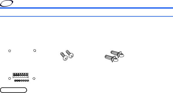
Check the enclosed items.
Plug-in option |
Mounting screw (M3 8 mm) |
Spacer |
|||||||||
..................................................1 |
...................... 2 (Refer to page 9) |
......................2 (Refer to page 9) |
|||||||||
|
|
|
|
|
|
|
|
|
|
|
|
|
|
|
|
|
|
|
|
|
|
|
|
|
|
|
|
|
|
|
|
|
|
|
|
|
|
|
|
|
|
|
|
|
|
|
|
|
|
|
|
|
|
|
|
|
|
|
|
|
|
|
|
|
|
|
|
|
|
|
|
|
|
|
|
|
|
|
|
|
|
|
|
|
|
|
|
|
|
|
|
|
|
|
|
|
|
|
|
|
|
|
|
|
|
|
|
|
|
|
|
|
|
|
|
|
|
|
|
 NOTE
NOTE
•Connection diagrams in this Instruction Manual appear with the control logic of the input terminals as sink logic, unless otherwise specified. (For the control logic, refer to the Instruction Manual of the inverter.)
6 |
|
PRE-OPERATION INSTRUCTIONS |
|

1.1.2SERIAL number check
The FR-A8APA can be used with the models of inverters listed below which have the following SERIAL number. Check the SERIAL number indicated on the inverter rating plate or package.
Rating plate example
SERIAL number


Country of origin
|
|
|
|
|
|
|
|
|
|
|
|
|
|
|
|
|
|
|
|
||||
|
|
|
|
|
|
|
|
||||
|
|
|
|
|
|
|
|
Symbol Year |
Month |
Control number |
|
SERIAL
The SERIAL consists of one symbol, two characters indicating the production year and month, and six characters indicating the control number.
The last digit of the production year is indicated as the Year, and 1 the Month is indicated by 1 to 9, X (October), Y (November), or Z (December).
FR-A800 series
Model |
Country of origin |
SERIAL number |
|
indication |
|||
|
|
||
FR-A820-00046(0.4K) to 04750(90K) |
MADE in Japan |
83 or later |
|
FR-A840-00023(0.4K) to 06830(280K) |
|
|
|
FR-A842-07700(315K) to 12120(500K) |
MADE in China |
84 or later |
|
FR-A846-00023(0.4K) to 03610(132K) |
|||
|
|
|
PRE-OPERATION INSTRUCTIONS |
|
7 |
|

1.2Component names
Front view
Terminal layout |
EA+ EB+ ER+ EC+ ED+ UP UN |
EAEB- EREC- ED- UP UN |
(a) |
(c) |
(a) |
(b) |
(a)Rear view (d)
 (a)
(a)

 (a)
(a)
(a)
Symbol |
Name |
Description |
Refer |
|
to page |
||||
|
|
|
||
a |
Mounting hole |
Used to fix this product to the inverter by inserting a mounting screw or a spacer. |
9 |
|
b |
Terminal block |
Used to connect the terminals of this product and an encoder. |
14 |
|
c |
CON2 connector |
Pulse output connector. |
― |
|
d |
Board mounted option connector |
Used to connect this product to the option connector on the inverter. |
9 |
8 |
|
PRE-OPERATION INSTRUCTIONS |
|

2 INSTALLATION AND WIRING
2.1Pre-installation instructions
Check that the inverter's input power and the control circuit power are both OFF.
 CAUTION
Do not install or remove this product while the inverter power is ON. Doing so may damage the inverter or this product.
To avoid damage due to static electricity, static electricity in your body must be discharged before you touch this product.
2.2Installation procedure
(1)Remove the inverter front cover. (Refer to Chapter 2 of the Instruction Manual (Detailed) of the inverter for instructions for removing the front cover.)
(2)Insert two spacers into the mounting holes that will not be
|
filled with mounting screws (see the diagrams on the next |
|
|
page to identify the holes ). |
|
(3) |
Fit the board mounted option connector on this product to |
|
|
the guide of the option connector on the inverter, and |
|
|
insert the option as far as it goes. |
|
(4) |
Fasten this product to the inverter using the two mounting |
Spacer |
|
screws through the holes on either side (tightening torque: |
|
|
0.33 to 0.40 N·m). If the screw holes do not line up, the |
|
connector may not be inserted deep enough. Check the connector.
Option connector on the inverter
 Spacer
2
Example of installation to connector 1
INSTALLATION AND WIRING |
9 |

•Insertion positions for screws and spacers FR-A800
Connector 3 |
|
|
Mounting screw |
Spacer |
Spacer |
Connector 2 |
Connector 1 |
Spacer |
Spacer |
Mounting screw |
Mounting screw |
FR-A800-E |
Connector 3 |
Ethernet connector |
Mounting screw |
Spacer |
Connector 1 |
Spacer |
Mounting screw |
Attach the option to connector 1 or 2. |
Attach the option to connector 1 or 3. |
(Do not attach the plug-in option to connector 3.) |
|
10 INSTALLATION AND WIRING
 NOTE
NOTE
•When installing/removing the plug-in option, hold the sides of the option. Do not press on the parts on the option circuit board. Stress applied to the parts by pressing, etc. may cause a failure.
•Be careful not to drop mounting screws during the installation or removal of the plug-in option.
•The priorities of vector control compatible plug-in options are defined as follows: FR-A8AL > FR-A8APS > FR-A8APA > FR-A8APR > FR-A8AP. The vector control compatible plug-in options with lower priority do not function.
•Only one option attached to the option connector with high priority can function at once if more than one option of the same name are installed together on an inverter. Priority is given to option connectors in descending order (1 to 3), and options having a lower priority do not function.
•When the inverter cannot recognize the option unit due to improper installation, etc., or when a fault occurs in the option or encoder, the protective function (E.1 to E.3 or E.OP1 to E.OP3) is activated and the inverter cannot be operated. The indication shown (when a fault occurs) depends on the connector used (option connector 1 to 3).
Mounted position |
Fault indication |
|
||
Option connector 1 |
|
|
|
|
|
|
|
|
|
Option connector 2 |
|
|
|
|
|
|
|
|
2 |
Option connector 3 |
|
|
|
|
|
|
|
|
|
•When removing the plug-in option, remove the two screws on either side, and then pull it straight out. Pressure applied to the option connectors and to the option board may break the option.
INSTALLATION AND WIRING |
|
11 |
|
 Loading...