


 Loading...
MELSEC iQ-F
FX5U User's Manual (Hardware)

SAFETY PRECAUTIONS
(Read these precautions before use.)
Before using this product, please read this manual and the relevant manuals introduced in this manual carefully and pay full attention to safety in order to handle the product correctly.
This manual classifies the safety precautions into two categories: [ WARNING] and [
 CAUTION].
WARNING |
Indicates that incorrect handling may cause hazardous conditions, resulting in |
death or severe injury. |
|
|
|
CAUTION |
Indicates that incorrect handling may cause hazardous conditions, resulting in |
minor or moderate injury or property damage. |
|
|
|
Depending on the circumstances, procedures indicated by [ CAUTION] may also cause severe injury. It is important to follow all precautions for personal safety.
Store this manual in a safe place so that it can be read whenever necessary. Always forward it to the end user.
[DESIGN PRECAUTIONS]
 WARNING
●Make sure to set up the following safety circuits outside the PLC to ensure safe system operation even during external power supply problems or PLC failure. Otherwise, malfunctions may cause serious accidents.
-Most importantly, set up the following: an emergency stop circuit, a protection circuit, an interlock circuit for opposite movements (such as forward vs. reverse rotation), and an interlock circuit to prevent damage to the equipment at the upper and lower positioning limits.
-Note that when the CPU module detects an error, such as a watchdog timer error, during selfdiagnosis, all outputs are turned off. Also, when an error that cannot be detected by the CPU module occurs in an input/output control block, output control may be disabled. External circuits and mechanisms should be designed to ensure safe machine operation in such a case.
-Note that the output current of the 24 V DC service power supply varies depending on the model and the absence/presence of extension modules. If an overload occurs, the voltage automatically drops, inputs in the PLC are disabled, and all outputs are turned off. External circuits and mechanisms should be designed to ensure safe machine operation in such a case.
-Note that when an error occurs in a relay or transistor of an output circuit, the output might stay on or off. For output signals that may lead to serious accidents, external circuits and mechanisms should be designed to ensure safe machine operation.
●Construct an interlock circuit in the program so that the whole system always operates on the safe side before executing the control (for data change) of the PLC in operation.
Read the manual thoroughly and ensure complete safety before executing other controls (for program change, parameter change, forced output and operation status change) of the PLC in operation. Otherwise, the machine may be damaged and accidents may occur due to erroneous operations.
●In an output circuit, when a load current exceeding the current rating or an overcurrent caused by a load short-circuit flows for a long time, it may cause smoke and fire. To prevent this, configure an external safety circuit, such as a fuse.
●For the operating status of each station after a communication failure of the network, refer to relevant manuals for the network. Incorrect output or malfunction may result in an accident.
1

[DESIGN PRECAUTIONS]
 CAUTION
●When an inductive load such as a lamp, heater, or solenoid valve is controlled, a large current (approximately ten times greater than normal) may flow when the output is turned from off to on. Take proper measures so that the flowing current does not exceed the value corresponding to the maximum load specification of the resistance load.
●After the CPU module is powered on or is reset, the time taken to enter the RUN status varies depending on the system configuration, parameter settings, and/or program size.
Design circuits so that the entire system will always operate safely, regardless of this variation in time.
●Simultaneously turn on and off the power supplies of the CPU module and extension modules.
●If a long-time power failure or an abnormal voltage drop occurs, the PLC stops, and output is turned off. When the power supply is restored, it will automatically restart (when the RUN/STOP/RESET switch is on RUN side).
[INSTALLATION PRECAUTIONS]
 WARNING
●Make sure to cut off all phases of the power supply externally before attempting installation or wiring work. Failure to do so may cause electric shock or damage to the product.
●Use the product within the generic environment specifications described in Page 17 Generic Specifications of this manual.
Never use the product in areas with excessive dust, oily smoke, conductive dusts, corrosive gas (salt
air, Cl2, H2S, SO2 or NO2), flammable gas, vibration or impacts, or expose it to high temperature, condensation, or rain and wind.
If the product is used in such conditions, electric shock, fire, malfunctions, deterioration or damage may occur.
2

[INSTALLATION PRECAUTIONS]
 CAUTION
●Do not touch the conductive parts of the product directly. Doing so may cause device failures or malfunctions.
●When drilling screw holes or wiring, make sure that cutting and wiring debris do not enter the ventilation slits of the PLC. Failure to do so may cause fire, equipment failures or malfunctions.
●For product supplied together with a dust proof sheet, the sheet should be affixed to the ventilation slits before the installation and wiring work in order to block foreign objects such as cutting and wiring debris.
However, when the installation work is completed, make sure to remove the sheet to provide adequate ventilation. Failure to do so may cause fire, equipment failures or malfunctions.
●Install the product on a flat surface. If the mounting surface is rough, undue force will be applied to the PC board, thereby causing nonconformities.
●Install the product securely using a DIN rail or mounting screws.
●Connect the expansion board and expansion adapter securely to their designated connectors. Loose connections may cause malfunctions.
●Make sure to affix the expansion board with tapping screws. Tightening torque should follow the specifications in the manual. If the screws are tightened outside of the specified torque range, poor connections may cause malfunctions.
●Work carefully when using a screwdriver during product installation. Failure to do so may cause damage to the product or accidents.
●Connect the extension cables, peripheral device cables, input/output cables and battery connecting cable securely to their designated connectors. Loose connections may cause malfunctions.
●When using an SD memory card, insert it into the SD memory card slot. Check that it is inserted completely. Poor contact may cause malfunction.
●Turn off the power to the PLC before attaching or detaching the following devices. Failure to do so may cause device failures or malfunctions.
-Peripheral devices, expansion board and expansion adapter
-Extension modules and bus conversion module
-Battery
3

[WIRING PRECAUTIONS]
 WARNING
●Make sure to cut off all phases of the power supply externally before attempting installation or wiring work. Failure to do so may cause electric shock or damage to the product.
●Make sure to attach the terminal cover, provided as an accessory, before turning on the power or initiating operation after installation or wiring work. Failure to do so may cause electric shock.
●The temperature rating of the cable should be 80 or more.
●Make sure to wire the screw terminal block in accordance with the following precautions. Failure to do so may cause electric shock, equipment failures, a short-circuit, wire breakage, malfunctions, or damage to the product.
-Wire terminals should follow the dimensions described in the manual.
-Tightening torque should follow the specifications in the manual.
-Tighten the screws using a Phillips-head screwdriver No. 2 (shaft diameter 6 mm (0.24") or less). Make sure that the screwdriver does not touch the partition part of the terminal block.
●Make sure to wire the terminal block (European type) in accordance with the following precautions. Failure to do so may cause electric shock, equipment failures, a short-circuit, wire breakage, malfunctions, or damage to the product.
-Wire terminals should follow the dimensions described in the manual.
-Tightening torque should follow the specifications in the manual.
-Twist the ends of stranded wires and make sure that there are no loose wires.
-Do not solder-plate the electric wire ends.
-Do not connect more than the specified number of wires or electric wires of unspecified size.
-Affix the electric wires so that neither the terminal block nor the connected parts are directly stressed.
[WIRING PRECAUTIONS]
 CAUTION
●Do not supply power to the [24+] and [24V] terminals (24 V DC service power supply) on the CPU module or extension modules. Doing so may cause damage to the product.
●Perform class D grounding (grounding resistance: 100 or less) of the grounding terminal on the CPU module and extension modules with a wire 2 mm2 or thicker.
However, do not use common grounding (refer to Page 78 Grounding) with heavy electrical systems.
●Connect the power supply wiring to the dedicated terminals described in this manual. If an AC power supply is connected to a DC input/output terminal or DC power supply terminal, the PLC will burn out.
●Do not wire vacant terminals externally. Doing so may cause damage to the product.
●Install module so that excessive force will not be applied to terminal blocks, power connectors, I/O connectors, communication connectors, or communication cables. Failure to do so may result in wire damage/breakage or PLC failure.
4

 CAUTION
●Make sure to observe the following precautions in order to prevent any damage to the machinery or accidents due to malfunction of the PLC caused by abnormal data written to the PLC due to the effects of noise.
-Do not bundle the power line, control line and communication cables together with or lay them close to the main circuit, high-voltage line, load line or power line. As a guideline, lay the power line, control line and connection cables at least 100 mm (3.94") away from the main circuit, highvoltage line, load line or power line.
-Ground the shield of the shield wire or shielded cable at one point on the PLC. However, do not use common grounding with heavy electrical systems.
-Ground the shield of the analog input/output cable at one point on the signal receiving side. Do not use common grounding with heavy electrical systems.
[STARTUP AND MAINTENANCE PRECAUTIONS]
 WARNING
●Do not touch any terminal while the PLC's power is on. Doing so may cause electric shock or malfunctions.
●Before cleaning or retightening terminals, cut off all phases of the power supply externally. Failure to do so may cause electric shock.
●Before modifying the program in mid-operation, forcing output, running or stopping the PLC, read through this manual carefully, and ensure complete safety. An operation error may damage the machinery or cause accidents.
●Do not change the program in the PLC from two or more peripheral equipment devices at the same time. (i.e. from an engineering tool and a GOT) Doing so may cause destruction or malfunction of the PLC program.
●Use the battery for memory backup in conformance to this manual.
-Use the battery for the specified purpose only.
-Connect the battery correctly.
-Do not charge, disassemble, heat, put in fire, short-circuit, connect reversely, weld, swallow or burn the battery, or apply excessive force (vibration, impact, drop, etc.) to the battery.
-Do not store or use the battery at high temperatures or expose to direct sunlight.
-Do not expose to water, bring near fire or touch liquid leakage or other contents directly. Incorrect handling of the battery may cause excessive heat, bursting, ignition, liquid leakage or deformation, and lead to injury, fire or failures and malfunction of facilities and other equipment.
5

[STARTUP AND MAINTENANCE PRECAUTIONS]
 CAUTION
●Do not disassemble or modify the PLC. Doing so may cause fire, equipment failures, or malfunctions. *For repair, contact your local Mitsubishi Electric representative.
●After the first use of the SD memory card, do not insert/remove the memory card more than 500 times. Insertion/removal 500 times or more may cause malfunction.
●Turn off the power to the PLC before connecting or disconnecting any extension cable. Failure to do so may cause device failures or malfunctions.
●Turn off the power to the PLC before attaching or detaching the following devices. Failure to do so may cause device failures or malfunctions.
-Peripheral devices, expansion board and expansion adapter
-Extension modules and bus conversion module
-Battery
[OPERATION PRECAUTIONS]
 CAUTION
●Construct an interlock circuit in the program to ensure safe operation for the whole system when executing control (for data change) of the PLC in operation. Read the manual thoroughly and ensure complete safety before executing other controls (for program change, parameter change, forced output and operation status change) of the PLC in operation. Otherwise, the machine may be damaged and accidents may occur by erroneous operations.
[DISPOSAL PRECAUTIONS]
 CAUTION
●Please contact a certified electronic waste disposal company for the environmentally safe recycling and disposal of your device.
●When disposing of batteries, separate them from other waste according to local regulations. For details on the Battery Directive in EU countries, refer to Page 144 Handling of Batteries and Devices with Built-in Batteries in EU Member States.
6

[TRANSPORTATION PRECAUTIONS]
 CAUTION
●When transporting the PLC with the optional battery, turn on the PLC before shipment, confirm that the battery mode is set in PLC parameters and the BAT LED is OFF, and check the battery life. If the PLC is transported with the BAT LED on or the battery exhausted, the battery-backed data may be lost during transportation.
●The PLC is a precision instrument. During transportation, avoid impacts larger than those specified in the general specifications ( Page 17 Generic Specifications) by using dedicated packaging boxes and shock-absorbing palettes. Failure to do so may cause failures in the PLC. After transportation, verify operation of the PLC and check for damage of the mounting part, etc.
●When transporting lithium batteries, follow required transportation regulations. For details on the regulated products, refer to Page 144 Handling of Batteries and Devices with Built-in Batteries in EU Member States.
●Fumigants that contain halogen materials such as fluorine, chlorine, bromine, and iodine used for disinfecting and protecting wooden packaging from insects will cause malfunction in Mitsubishi products. Please take necessary precautions to ensure that residual fumigants do not enter the product, or treat packaging with methods other than fumigation (heat method). Additionally, disinfect and protect wood from insects before packing.
INTRODUCTION
This manual contains text, diagrams and explanations which will guide the reader in the correct installation, safe use and operation of the FX5U Programmable Controllers and should be read and understood before attempting to install or use the module.
Always forward it to the end user.
Regarding use of this product
•This product has been manufactured as a general-purpose part for general industries, and has not been designed or manufactured to be incorporated in a device or system used in purposes related to human life.
•Before using the product for special purposes such as nuclear power, electric power, aerospace, medicine or passenger movement vehicles, consult Mitsubishi Electric.
•This product has been manufactured under strict quality control. However when installing the product where major accidents or losses could occur if the product fails, install appropriate backup or failsafe functions in the system.
Note
•If in doubt at any stage during the installation of the product, always consult a professional electrical engineer who is qualified and trained in the local and national standards. If in doubt about the operation or use, please consult the nearest Mitsubishi Electric representative.
•Since the examples indicated by this manual, technical bulletin, catalog, etc. are used as a reference, please use it after confirming the function and safety of the equipment and system. Mitsubishi Electric will accept no responsibility for actual use of the product based on these illustrative examples.
•This manual content, specification etc. may be changed, without a notice, for improvement.
•The information in this manual has been carefully checked and is believed to be accurate; however, if you notice a doubtful point, an error, etc., please contact the nearest Mitsubishi Electric representative. When doing so, please provide the manual number given at the end of this manual.
7

CONTENTS
SAFETY PRECAUTIONS . . . . . . . . . . . . . . . . . . . . . . . . . . . . . . . . . . . . . . . . . . . . . . . . . . . . . . . . . . . . . . . . . . . .1 INTRODUCTION. . . . . . . . . . . . . . . . . . . . . . . . . . . . . . . . . . . . . . . . . . . . . . . . . . . . . . . . . . . . . . . . . . . . . . . . . . .7 RELEVANT MANUALS . . . . . . . . . . . . . . . . . . . . . . . . . . . . . . . . . . . . . . . . . . . . . . . . . . . . . . . . . . . . . . . . . . . . .12 TERMS . . . . . . . . . . . . . . . . . . . . . . . . . . . . . . . . . . . . . . . . . . . . . . . . . . . . . . . . . . . . . . . . . . . . . . . . . . . . . . . . .12
CHAPTER 1 |
OUTLINE |
14 |
1.1 Part Names. . . . . . . . . . . . . . . . . . . . . . . . . . . . . . . . . . . . . . . . . . . . . . . . . . . . . . . . . . . . . . . . . . . . . . . . . . . . |
. 14 |
|
Front panel |
. . . . . . . . . . . . . . . . . . . . . . . . . . . . . . . . . . . . . . . . . . . . . . . . . . . . . . . . . . . . . . . . . . . . . . . . . . . . . |
14 |
Side . . . . . . |
. . . . . . . . . . . . . . . . . . . . . . . . . . . . . . . . . . . . . . . . . . . . . . . . . . . . . . . . . . . . . . . . . . . . . . . . . . . . . |
16 |
CHAPTER 2 |
SPECIFICATIONS |
17 |
2.1 Generic Specifications . . . . . . . . . . . . . . . . . . . . . . . . . . . . . . . . . . . . . . . . . . . . . . . . . . . . . . . . . . . . . . . . . . . 17
2.2 Power Supply Specifications . . . . . . . . . . . . . . . . . . . . . . . . . . . . . . . . . . . . . . . . . . . . . . . . . . . . . . . . . . . . . . 18
AC power supply . . . . . . . . . . . . . . . . . . . . . . . . . . . . . . . . . . . . . . . . . . . . . . . . . . . . . . . . . . . . . . . . . . . . . . . . . 18
2.3 Input Specifications . . . . . . . . . . . . . . . . . . . . . . . . . . . . . . . . . . . . . . . . . . . . . . . . . . . . . . . . . . . . . . . . . . . . . 19
24 V DC Input (sink/source) . . . . . . . . . . . . . . . . . . . . . . . . . . . . . . . . . . . . . . . . . . . . . . . . . . . . . . . . . . . . . . . . 19
2.4 Output Specifications . . . . . . . . . . . . . . . . . . . . . . . . . . . . . . . . . . . . . . . . . . . . . . . . . . . . . . . . . . . . . . . . . . . . 21
Relay output . . . . . . . . . . . . . . . . . . . . . . . . . . . . . . . . . . . . . . . . . . . . . . . . . . . . . . . . . . . . . . . . . . . . . . . . . . . . 21
Transistor output . . . . . . . . . . . . . . . . . . . . . . . . . . . . . . . . . . . . . . . . . . . . . . . . . . . . . . . . . . . . . . . . . . . . . . . . . 22
2.5 Input/Output Derating Curve . . . . . . . . . . . . . . . . . . . . . . . . . . . . . . . . . . . . . . . . . . . . . . . . . . . . . . . . . . . . . . 22
2.6 Performance Specifications . . . . . . . . . . . . . . . . . . . . . . . . . . . . . . . . . . . . . . . . . . . . . . . . . . . . . . . . . . . . . . . 23
2.7 Built-in Analog Specifications . . . . . . . . . . . . . . . . . . . . . . . . . . . . . . . . . . . . . . . . . . . . . . . . . . . . . . . . . . . . . 25
Analog input. . . . . . . . . . . . . . . . . . . . . . . . . . . . . . . . . . . . . . . . . . . . . . . . . . . . . . . . . . . . . . . . . . . . . . . . . . . . . 25
Analog output . . . . . . . . . . . . . . . . . . . . . . . . . . . . . . . . . . . . . . . . . . . . . . . . . . . . . . . . . . . . . . . . . . . . . . . . . . . 25
2.8 Communication Specifications . . . . . . . . . . . . . . . . . . . . . . . . . . . . . . . . . . . . . . . . . . . . . . . . . . . . . . . . . . . . 26
Built-in Ethernet communication . . . . . . . . . . . . . . . . . . . . . . . . . . . . . . . . . . . . . . . . . . . . . . . . . . . . . . . . . . . . . 26
Built-in RS-485 communication . . . . . . . . . . . . . . . . . . . . . . . . . . . . . . . . . . . . . . . . . . . . . . . . . . . . . . . . . . . . . . 26
2.9 External Dimensions . . . . . . . . . . . . . . . . . . . . . . . . . . . . . . . . . . . . . . . . . . . . . . . . . . . . . . . . . . . . . . . . . . . . . 27
CPU module . . . . . . . . . . . . . . . . . . . . . . . . . . . . . . . . . . . . . . . . . . . . . . . . . . . . . . . . . . . . . . . . . . . . . . . . . . . . 27
2.10 Terminal Layout . . . . . . . . . . . . . . . . . . . . . . . . . . . . . . . . . . . . . . . . . . . . . . . . . . . . . . . . . . . . . . . . . . . . . . . . . 28
CHAPTER 3 PRODUCT LIST |
31 |
3.1 Overall Configuration . . . . . . . . . . . . . . . . . . . . . . . . . . . . . . . . . . . . . . . . . . . . . . . . . . . . . . . . . . . . . . . . . . . . 31
3.2 CPU Module . . . . . . . . . . . . . . . . . . . . . . . . . . . . . . . . . . . . . . . . . . . . . . . . . . . . . . . . . . . . . . . . . . . . . . . . . . . . 32
3.3 I/O Module . . . . . . . . . . . . . . . . . . . . . . . . . . . . . . . . . . . . . . . . . . . . . . . . . . . . . . . . . . . . . . . . . . . . . . . . . . . . . 33
3.4 Intelligent Function Module . . . . . . . . . . . . . . . . . . . . . . . . . . . . . . . . . . . . . . . . . . . . . . . . . . . . . . . . . . . . . . . 34
FX5 intelligent Function Module . . . . . . . . . . . . . . . . . . . . . . . . . . . . . . . . . . . . . . . . . . . . . . . . . . . . . . . . . . . . . 34
FX3 intelligent Function Module . . . . . . . . . . . . . . . . . . . . . . . . . . . . . . . . . . . . . . . . . . . . . . . . . . . . . . . . . . . . . 34
3.5 Expansion Board . . . . . . . . . . . . . . . . . . . . . . . . . . . . . . . . . . . . . . . . . . . . . . . . . . . . . . . . . . . . . . . . . . . . . . . . 35
3.6 Expansion Adapter . . . . . . . . . . . . . . . . . . . . . . . . . . . . . . . . . . . . . . . . . . . . . . . . . . . . . . . . . . . . . . . . . . . . . . 35
3.7 Extension Power Supply Module . . . . . . . . . . . . . . . . . . . . . . . . . . . . . . . . . . . . . . . . . . . . . . . . . . . . . . . . . . . 36
FX5 expansion power supply module . . . . . . . . . . . . . . . . . . . . . . . . . . . . . . . . . . . . . . . . . . . . . . . . . . . . . . . . . 36
FX3 expansion power supply module . . . . . . . . . . . . . . . . . . . . . . . . . . . . . . . . . . . . . . . . . . . . . . . . . . . . . . . . . 36
3.8 Bus Conversion Module . . . . . . . . . . . . . . . . . . . . . . . . . . . . . . . . . . . . . . . . . . . . . . . . . . . . . . . . . . . . . . . . . . 36
3.9 SD Memory Card . . . . . . . . . . . . . . . . . . . . . . . . . . . . . . . . . . . . . . . . . . . . . . . . . . . . . . . . . . . . . . . . . . . . . . . . 36
3.10 Battery . . . . . . . . . . . . . . . . . . . . . . . . . . . . . . . . . . . . . . . . . . . . . . . . . . . . . . . . . . . . . . . . . . . . . . . . . . . . . . . . 37
3.11 Communication Cable. . . . . . . . . . . . . . . . . . . . . . . . . . . . . . . . . . . . . . . . . . . . . . . . . . . . . . . . . . . . . . . . . . . . 37
3.12 Engineering Tool . . . . . . . . . . . . . . . . . . . . . . . . . . . . . . . . . . . . . . . . . . . . . . . . . . . . . . . . . . . . . . . . . . . . . . . . 37
8
CHAPTER 4 SYSTEM CONFIGURATION |
38 |
4.1 Rules of System Configuration . . . . . . . . . . . . . . . . . . . . . . . . . . . . . . . . . . . . . . . . . . . . . . . . . . . . . . . . . . . . 39 4.2 Limitations on the Number of Connected Extension Devices . . . . . . . . . . . . . . . . . . . . . . . . . . . . . . . . . . . 41
Number of connected expansion boards. . . . . . . . . . . . . . . . . . . . . . . . . . . . . . . . . . . . . . . . . . . . . . . . . . . . . . . 41 Number of connected expansion adapters . . . . . . . . . . . . . . . . . . . . . . . . . . . . . . . . . . . . . . . . . . . . . . . . . . . . . 41 Number of connected extension modules . . . . . . . . . . . . . . . . . . . . . . . . . . . . . . . . . . . . . . . . . . . . . . . . . . . . . . 42
4.3 Limitation on the Number of Input/Output Points . . . . . . . . . . . . . . . . . . . . . . . . . . . . . . . . . . . . . . . . . . . . . 45
Total number of I/O points and remote I/O points . . . . . . . . . . . . . . . . . . . . . . . . . . . . . . . . . . . . . . . . . . . . . . . . 45 Calculation of number of input/output points . . . . . . . . . . . . . . . . . . . . . . . . . . . . . . . . . . . . . . . . . . . . . . . . . . . . 46 Calculation of number of remote I/O points . . . . . . . . . . . . . . . . . . . . . . . . . . . . . . . . . . . . . . . . . . . . . . . . . . . . . 46
4.4 Limitation on Current Consumption . . . . . . . . . . . . . . . . . . . . . . . . . . . . . . . . . . . . . . . . . . . . . . . . . . . . . . . . 48
Power supply check from the CPU module (current consumption calculation) . . . . . . . . . . . . . . . . . . . . . . . . . . 48 Power supply check from the powered input/output module (current consumption calculation) . . . . . . . . . . . . . 49 Power supply check from extension power supply module (current consumption calculation) . . . . . . . . . . . . . . 51
4.5 Rules of System Configuration and Examples of Reconfiguration . . . . . . . . . . . . . . . . . . . . . . . . . . . . . . . 53
System configuration example . . . . . . . . . . . . . . . . . . . . . . . . . . . . . . . . . . . . . . . . . . . . . . . . . . . . . . . . . . . . . . 53 System reconfiguration example . . . . . . . . . . . . . . . . . . . . . . . . . . . . . . . . . . . . . . . . . . . . . . . . . . . . . . . . . . . . . 57
4.6 Numbers and Assignment in System . . . . . . . . . . . . . . . . . . . . . . . . . . . . . . . . . . . . . . . . . . . . . . . . . . . . . . . 62
Module input/output number . . . . . . . . . . . . . . . . . . . . . . . . . . . . . . . . . . . . . . . . . . . . . . . . . . . . . . . . . . . . . . . . 62 Module number of Extension modules . . . . . . . . . . . . . . . . . . . . . . . . . . . . . . . . . . . . . . . . . . . . . . . . . . . . . . . . 62
CHAPTER 5 INSTALLATION |
63 |
5.1 Installation Location . . . . . . . . . . . . . . . . . . . . . . . . . . . . . . . . . . . . . . . . . . . . . . . . . . . . . . . . . . . . . . . . . . . . . 63
Installation location in enclosure . . . . . . . . . . . . . . . . . . . . . . . . . . . . . . . . . . . . . . . . . . . . . . . . . . . . . . . . . . . . . 63 Spaces in enclosure . . . . . . . . . . . . . . . . . . . . . . . . . . . . . . . . . . . . . . . . . . . . . . . . . . . . . . . . . . . . . . . . . . . . . . 63 Layout in enclosure . . . . . . . . . . . . . . . . . . . . . . . . . . . . . . . . . . . . . . . . . . . . . . . . . . . . . . . . . . . . . . . . . . . . . . . 63
5.2 Examination for Installation Method in Enclosure . . . . . . . . . . . . . . . . . . . . . . . . . . . . . . . . . . . . . . . . . . . . . 64 5.3 Procedures for Installing on and Detaching from DIN Rail . . . . . . . . . . . . . . . . . . . . . . . . . . . . . . . . . . . . . . 65
Preparation for installation. . . . . . . . . . . . . . . . . . . . . . . . . . . . . . . . . . . . . . . . . . . . . . . . . . . . . . . . . . . . . . . . . . 65 Installation of CPU module . . . . . . . . . . . . . . . . . . . . . . . . . . . . . . . . . . . . . . . . . . . . . . . . . . . . . . . . . . . . . . . . . 65 Installation of extension module . . . . . . . . . . . . . . . . . . . . . . . . . . . . . . . . . . . . . . . . . . . . . . . . . . . . . . . . . . . . . 66 Removal of CPU module . . . . . . . . . . . . . . . . . . . . . . . . . . . . . . . . . . . . . . . . . . . . . . . . . . . . . . . . . . . . . . . . . . . 66
5.4 Procedures for Installing Directly (with M4 Screws) . . . . . . . . . . . . . . . . . . . . . . . . . . . . . . . . . . . . . . . . . . . 67
Hole pitches for direct mounting . . . . . . . . . . . . . . . . . . . . . . . . . . . . . . . . . . . . . . . . . . . . . . . . . . . . . . . . . . . . . 67 Hole pitches when extension module connected . . . . . . . . . . . . . . . . . . . . . . . . . . . . . . . . . . . . . . . . . . . . . . . . 69 Installation of CPU module . . . . . . . . . . . . . . . . . . . . . . . . . . . . . . . . . . . . . . . . . . . . . . . . . . . . . . . . . . . . . . . . . 69 Installation of extension module . . . . . . . . . . . . . . . . . . . . . . . . . . . . . . . . . . . . . . . . . . . . . . . . . . . . . . . . . . . . . 70
5.5 Connection Methods for CPU Module and Extension Devices. . . . . . . . . . . . . . . . . . . . . . . . . . . . . . . . . . . 71
Connection of extension devices. . . . . . . . . . . . . . . . . . . . . . . . . . . . . . . . . . . . . . . . . . . . . . . . . . . . . . . . . . . . . 71 Connection method A - connection of an expansion board. . . . . . . . . . . . . . . . . . . . . . . . . . . . . . . . . . . . . . . . . 71 Connection method B - connection of an expansion adapter . . . . . . . . . . . . . . . . . . . . . . . . . . . . . . . . . . . . . . . 72 Connection method C - connection of an extension module to the CPU module . . . . . . . . . . . . . . . . . . . . . . . . 72 Connection method D - connection between extension modules . . . . . . . . . . . . . . . . . . . . . . . . . . . . . . . . . . . . 73 Connection method E - connection of an extension module to the bus conversion module . . . . . . . . . . . . . . . . 73
CHAPTER 6 WIRING |
74 |
6.1 Wiring Preparations . . . . . . . . . . . . . . . . . . . . . . . . . . . . . . . . . . . . . . . . . . . . . . . . . . . . . . . . . . . . . . . . . . . . . 74
Wiring procedure . . . . . . . . . . . . . . . . . . . . . . . . . . . . . . . . . . . . . . . . . . . . . . . . . . . . . . . . . . . . . . . . . . . . . . . . . 74
Removal and installation of removable terminal block . . . . . . . . . . . . . . . . . . . . . . . . . . . . . . . . . . . . . . . . . . . . 75
6.2 Cable Connecting Procedure . . . . . . . . . . . . . . . . . . . . . . . . . . . . . . . . . . . . . . . . . . . . . . . . . . . . . . . . . . . . . . 76
CONTENTS
9

Screw terminal block . . . . . . . . . . . . . . . . . . . . . . . . . . . . . . . . . . . . . . . . . . . . . . . . . . . . . . . . . . . . . . . . . . . . . . 76 European-type terminal block . . . . . . . . . . . . . . . . . . . . . . . . . . . . . . . . . . . . . . . . . . . . . . . . . . . . . . . . . . . . . . . 77
6.3 Grounding . . . . . . . . . . . . . . . . . . . . . . . . . . . . . . . . . . . . . . . . . . . . . . . . . . . . . . . . . . . . . . . . . . . . . . . . . . . . . 78 6.4 Power Supply Wiring. . . . . . . . . . . . . . . . . . . . . . . . . . . . . . . . . . . . . . . . . . . . . . . . . . . . . . . . . . . . . . . . . . . . . 79
Examples of AC power supply wiring . . . . . . . . . . . . . . . . . . . . . . . . . . . . . . . . . . . . . . . . . . . . . . . . . . . . . . . . . 79
6.5 Input Wiring . . . . . . . . . . . . . . . . . . . . . . . . . . . . . . . . . . . . . . . . . . . . . . . . . . . . . . . . . . . . . . . . . . . . . . . . . . . . 83
24 V DC input (Sink and source input type) . . . . . . . . . . . . . . . . . . . . . . . . . . . . . . . . . . . . . . . . . . . . . . . . . . . . 83 Input wiring example . . . . . . . . . . . . . . . . . . . . . . . . . . . . . . . . . . . . . . . . . . . . . . . . . . . . . . . . . . . . . . . . . . . . . . 87
6.6 Output Wiring. . . . . . . . . . . . . . . . . . . . . . . . . . . . . . . . . . . . . . . . . . . . . . . . . . . . . . . . . . . . . . . . . . . . . . . . . . . 89
Relay output . . . . . . . . . . . . . . . . . . . . . . . . . . . . . . . . . . . . . . . . . . . . . . . . . . . . . . . . . . . . . . . . . . . . . . . . . . . . 89 Transistor output . . . . . . . . . . . . . . . . . . . . . . . . . . . . . . . . . . . . . . . . . . . . . . . . . . . . . . . . . . . . . . . . . . . . . . . . . 92 Output wiring example. . . . . . . . . . . . . . . . . . . . . . . . . . . . . . . . . . . . . . . . . . . . . . . . . . . . . . . . . . . . . . . . . . . . . 95
6.7 Analog Wiring . . . . . . . . . . . . . . . . . . . . . . . . . . . . . . . . . . . . . . . . . . . . . . . . . . . . . . . . . . . . . . . . . . . . . . . . . . 98 6.8 Examples of Wiring for Various Uses . . . . . . . . . . . . . . . . . . . . . . . . . . . . . . . . . . . . . . . . . . . . . . . . . . . . . . . 99
Built-in positioning function . . . . . . . . . . . . . . . . . . . . . . . . . . . . . . . . . . . . . . . . . . . . . . . . . . . . . . . . . . . . . . . . . 99 Communication function . . . . . . . . . . . . . . . . . . . . . . . . . . . . . . . . . . . . . . . . . . . . . . . . . . . . . . . . . . . . . . . . . . . 99 High-speed counter . . . . . . . . . . . . . . . . . . . . . . . . . . . . . . . . . . . . . . . . . . . . . . . . . . . . . . . . . . . . . . . . . . . . . . 100 Interruption . . . . . . . . . . . . . . . . . . . . . . . . . . . . . . . . . . . . . . . . . . . . . . . . . . . . . . . . . . . . . . . . . . . . . . . . . . . . 104 Digital Switch . . . . . . . . . . . . . . . . . . . . . . . . . . . . . . . . . . . . . . . . . . . . . . . . . . . . . . . . . . . . . . . . . . . . . . . . . . . 105 Input Matrix . . . . . . . . . . . . . . . . . . . . . . . . . . . . . . . . . . . . . . . . . . . . . . . . . . . . . . . . . . . . . . . . . . . . . . . . . . . . 107 Seven Segment with Latch . . . . . . . . . . . . . . . . . . . . . . . . . . . . . . . . . . . . . . . . . . . . . . . . . . . . . . . . . . . . . . . . 108
CHAPTER 7 OPERATION ADJUSTMENT |
110 |
7.1 Preparation for Operation. . . . . . . . . . . . . . . . . . . . . . . . . . . . . . . . . . . . . . . . . . . . . . . . . . . . . . . . . . . . . . . . 110
Preliminary inspection . . . . . . . . . . . . . . . . . . . . . . . . . . . . . . . . . . . . . . . . . . . . . . . . . . . . . . . . . . . . . . . . . . . . 110 Procedure until operation . . . . . . . . . . . . . . . . . . . . . . . . . . . . . . . . . . . . . . . . . . . . . . . . . . . . . . . . . . . . . . . . . 111 Connection with a personal computer . . . . . . . . . . . . . . . . . . . . . . . . . . . . . . . . . . . . . . . . . . . . . . . . . . . . . . . . 112
7.2 Operation and Test . . . . . . . . . . . . . . . . . . . . . . . . . . . . . . . . . . . . . . . . . . . . . . . . . . . . . . . . . . . . . . . . . . . . . 113
Self-diagnostic function . . . . . . . . . . . . . . . . . . . . . . . . . . . . . . . . . . . . . . . . . . . . . . . . . . . . . . . . . . . . . . . . . . . 113 Monitoring and debugging. . . . . . . . . . . . . . . . . . . . . . . . . . . . . . . . . . . . . . . . . . . . . . . . . . . . . . . . . . . . . . . . . 113
7.3 Running, Stopping, and Resetting. . . . . . . . . . . . . . . . . . . . . . . . . . . . . . . . . . . . . . . . . . . . . . . . . . . . . . . . . 114
Methods of running, stopping, and resetting . . . . . . . . . . . . . . . . . . . . . . . . . . . . . . . . . . . . . . . . . . . . . . . . . . . 114
CHAPTER 8 MAINTENANCE AND INSPECTION |
115 |
8.1 Daily Inspection . . . . . . . . . . . . . . . . . . . . . . . . . . . . . . . . . . . . . . . . . . . . . . . . . . . . . . . . . . . . . . . . . . . . . . . . 115 8.2 Periodic Inspection . . . . . . . . . . . . . . . . . . . . . . . . . . . . . . . . . . . . . . . . . . . . . . . . . . . . . . . . . . . . . . . . . . . . . 115 8.3 Battery . . . . . . . . . . . . . . . . . . . . . . . . . . . . . . . . . . . . . . . . . . . . . . . . . . . . . . . . . . . . . . . . . . . . . . . . . . . . . . . 116
Part names . . . . . . . . . . . . . . . . . . . . . . . . . . . . . . . . . . . . . . . . . . . . . . . . . . . . . . . . . . . . . . . . . . . . . . . . . . . . 116 Specifications . . . . . . . . . . . . . . . . . . . . . . . . . . . . . . . . . . . . . . . . . . . . . . . . . . . . . . . . . . . . . . . . . . . . . . . . . . 116 Battery attachment . . . . . . . . . . . . . . . . . . . . . . . . . . . . . . . . . . . . . . . . . . . . . . . . . . . . . . . . . . . . . . . . . . . . . . 116 Battery replacement . . . . . . . . . . . . . . . . . . . . . . . . . . . . . . . . . . . . . . . . . . . . . . . . . . . . . . . . . . . . . . . . . . . . . 118 Special relay for low battery voltage . . . . . . . . . . . . . . . . . . . . . . . . . . . . . . . . . . . . . . . . . . . . . . . . . . . . . . . . . 119
CHAPTER 9 TROUBLESHOOTING |
120 |
9.1 Troubleshooting Procedure . . . . . . . . . . . . . . . . . . . . . . . . . . . . . . . . . . . . . . . . . . . . . . . . . . . . . . . . . . . . . . 120 9.2 Checking with LEDs . . . . . . . . . . . . . . . . . . . . . . . . . . . . . . . . . . . . . . . . . . . . . . . . . . . . . . . . . . . . . . . . . . . . 120
Checking the PWR LED . . . . . . . . . . . . . . . . . . . . . . . . . . . . . . . . . . . . . . . . . . . . . . . . . . . . . . . . . . . . . . . . . . 120 Checking the BAT LED . . . . . . . . . . . . . . . . . . . . . . . . . . . . . . . . . . . . . . . . . . . . . . . . . . . . . . . . . . . . . . . . . . . 120 Checking the ERR LED . . . . . . . . . . . . . . . . . . . . . . . . . . . . . . . . . . . . . . . . . . . . . . . . . . . . . . . . . . . . . . . . . . . 121 Checking the P.RUN LED . . . . . . . . . . . . . . . . . . . . . . . . . . . . . . . . . . . . . . . . . . . . . . . . . . . . . . . . . . . . . . . . . 121
10

9.3 Troubleshooting using the engineering tool . . . . . . . . . . . . . . . . . . . . . . . . . . . . . . . . . . . . . . . . . . . . . . . . 121
Module diagnostics (CPU Diagnostics) . . . . . . . . . . . . . . . . . . . . . . . . . . . . . . . . . . . . . . . . . . . . . . . . . . . . . . . 122
9.4 Error Status and Operations on Occurrence of an Error. . . . . . . . . . . . . . . . . . . . . . . . . . . . . . . . . . . . . . . 123 9.5 Backing Up the Data . . . . . . . . . . . . . . . . . . . . . . . . . . . . . . . . . . . . . . . . . . . . . . . . . . . . . . . . . . . . . . . . . . . . 124 9.6 Canceling Errors . . . . . . . . . . . . . . . . . . . . . . . . . . . . . . . . . . . . . . . . . . . . . . . . . . . . . . . . . . . . . . . . . . . . . . . 124 9.7 Troubleshooting for Each Symptom . . . . . . . . . . . . . . . . . . . . . . . . . . . . . . . . . . . . . . . . . . . . . . . . . . . . . . . 125
I/O operation (CPU module, I/O module) . . . . . . . . . . . . . . . . . . . . . . . . . . . . . . . . . . . . . . . . . . . . . . . . . . . . . 125 PLC write, PLC read . . . . . . . . . . . . . . . . . . . . . . . . . . . . . . . . . . . . . . . . . . . . . . . . . . . . . . . . . . . . . . . . . . . . . 126 Boot operation . . . . . . . . . . . . . . . . . . . . . . . . . . . . . . . . . . . . . . . . . . . . . . . . . . . . . . . . . . . . . . . . . . . . . . . . . . 126
APPENDIX |
127 |
Appendix 1 How to Check the Date of Manufacture . . . . . . . . . . . . . . . . . . . . . . . . . . . . . . . . . . . . . . . . . . . . . . . . 127 Appendix 2 Standards . . . . . . . . . . . . . . . . . . . . . . . . . . . . . . . . . . . . . . . . . . . . . . . . . . . . . . . . . . . . . . . . . . . . . . . . 128
Certification of UL, cUL standards. . . . . . . . . . . . . . . . . . . . . . . . . . . . . . . . . . . . . . . . . . . . . . . . . . . . . . . . . . . 128 Compliance with EC directive (CE Marking) . . . . . . . . . . . . . . . . . . . . . . . . . . . . . . . . . . . . . . . . . . . . . . . . . . . 128 Requirement for compliance with EMC directive. . . . . . . . . . . . . . . . . . . . . . . . . . . . . . . . . . . . . . . . . . . . . . . . 128 Requirement for compliance with LVD directive . . . . . . . . . . . . . . . . . . . . . . . . . . . . . . . . . . . . . . . . . . . . . . . . 129 Caution for compliance with EC Directive . . . . . . . . . . . . . . . . . . . . . . . . . . . . . . . . . . . . . . . . . . . . . . . . . . . . . 129
Appendix 3 I/O Module. . . . . . . . . . . . . . . . . . . . . . . . . . . . . . . . . . . . . . . . . . . . . . . . . . . . . . . . . . . . . . . . . . . . . . . . 132
Product configuration. . . . . . . . . . . . . . . . . . . . . . . . . . . . . . . . . . . . . . . . . . . . . . . . . . . . . . . . . . . . . . . . . . . . . 132 Product list. . . . . . . . . . . . . . . . . . . . . . . . . . . . . . . . . . . . . . . . . . . . . . . . . . . . . . . . . . . . . . . . . . . . . . . . . . . . . 132 Specifications . . . . . . . . . . . . . . . . . . . . . . . . . . . . . . . . . . . . . . . . . . . . . . . . . . . . . . . . . . . . . . . . . . . . . . . . . . 133 External dimensions and component names. . . . . . . . . . . . . . . . . . . . . . . . . . . . . . . . . . . . . . . . . . . . . . . . . . . 138 Terminal layout . . . . . . . . . . . . . . . . . . . . . . . . . . . . . . . . . . . . . . . . . . . . . . . . . . . . . . . . . . . . . . . . . . . . . . . . . 140
Appendix 4 SD Memory Card . . . . . . . . . . . . . . . . . . . . . . . . . . . . . . . . . . . . . . . . . . . . . . . . . . . . . . . . . . . . . . . . . . 141
Part names . . . . . . . . . . . . . . . . . . . . . . . . . . . . . . . . . . . . . . . . . . . . . . . . . . . . . . . . . . . . . . . . . . . . . . . . . . . . 141 Specifications . . . . . . . . . . . . . . . . . . . . . . . . . . . . . . . . . . . . . . . . . . . . . . . . . . . . . . . . . . . . . . . . . . . . . . . . . . 141 Insertion and removal of the SD memory card . . . . . . . . . . . . . . . . . . . . . . . . . . . . . . . . . . . . . . . . . . . . . . . . . 142
Appendix 5 Precautions for Battery Transportation . . . . . . . . . . . . . . . . . . . . . . . . . . . . . . . . . . . . . . . . . . . . . . . . 143
Control-subject product . . . . . . . . . . . . . . . . . . . . . . . . . . . . . . . . . . . . . . . . . . . . . . . . . . . . . . . . . . . . . . . . . . . 143 Precautions for transportation . . . . . . . . . . . . . . . . . . . . . . . . . . . . . . . . . . . . . . . . . . . . . . . . . . . . . . . . . . . . . . 143
Appendix 6 Handling of Batteries and Devices with Built-in Batteries in EU Member States . . . . . . . . . . . . . . 144
Disposal precautions . . . . . . . . . . . . . . . . . . . . . . . . . . . . . . . . . . . . . . . . . . . . . . . . . . . . . . . . . . . . . . . . . . . . . 144 Exportation precautions. . . . . . . . . . . . . . . . . . . . . . . . . . . . . . . . . . . . . . . . . . . . . . . . . . . . . . . . . . . . . . . . . . . 144
INDEX |
145 |
REVISIONS. . . . . . . . . . . . . . . . . . . . . . . . . . . . . . . . . . . . . . . . . . . . . . . . . . . . . . . . . . . . . . . . . . . . . . . . . . . . .146 WARRANTY . . . . . . . . . . . . . . . . . . . . . . . . . . . . . . . . . . . . . . . . . . . . . . . . . . . . . . . . . . . . . . . . . . . . . . . . . . . .147 TRADEMARKS . . . . . . . . . . . . . . . . . . . . . . . . . . . . . . . . . . . . . . . . . . . . . . . . . . . . . . . . . . . . . . . . . . . . . . . . . .148
CONTENTS
11

RELEVANT MANUALS
User's manuals for the applicable modules
Manual name <manual number> |
Description |
MELSEC iQ-F FX5U CPU Module Hardware Manual |
Describes the details of input/output specifications, wiring and installation of the |
<JY997D53401> |
FX5U CPU module from MELSEC iQ-F FX5U User's Manual (Hardware). |
|
|
MELSEC iQ-F FX5 User's Manual (Startup) |
Performance specifications, procedures before operation, and troubleshooting of the |
<JY997D58201> |
CPU module. |
|
|
MELSEC iQ-F FX5U User's Manual (Hardware) |
Describes the details of hardware of the FX5U CPU module, including input/output |
<JY997D55301> (This manual) |
specifications, wiring, installation, and maintenance. |
|
|
MELSEC iQ-F FX5UC User's Manual (Hardware) |
Describes the details of hardware of the FX5UC CPU module, including input/output |
<JY997D61401> |
specifications, wiring, installation, and maintenance. |
|
|
MELSEC iQ-F FX5 User's Manual (Application) |
Describes basic knowledge required for program design, functions of the CPU |
<JY997D55401> |
module, devices/labels, and parameters. |
|
|
MELSEC iQ-F FX5 Programming Manual (Program Design) |
Describes specifications of ladders, ST, FBD/LD, and other programs and labels. |
<JY997D55701> |
|
|
|
MELSEC iQ-F FX5 Programming Manual (Instructions, Standard |
Describes specifications of instructions and functions that can be used in programs. |
Functions/Function Blocks) |
|
<JY997D55801> |
|
|
|
MELSEC iQ-F FX5 User's Manual (Serial Communication) |
Describes N:N network, MELSEC Communication protocol, inverter communication, |
<JY997D55901> |
non-protocol communication, and predefined protocol support. |
|
|
MELSEC iQ-F FX5 User's Manual (MODBUS Communication) |
Describes MODBUS serial communication. |
<JY997D56101> |
|
|
|
MELSEC iQ-F FX5 User's Manual (Ethernet Communication) |
Describes the functions of the built-in Ethernet port communication function. |
<JY997D56201> |
|
|
|
MELSEC iQ-F FX5 User's Manual (SLMP) |
Explains methods for the device that is communicating with the CPU module by |
<JY997D56001> |
SLMP to read and write the data of the CPU module. |
|
|
MELSEC iQ-F FX5 User's Manual (Positioning Control) |
Describes the built-in positioning function. |
<JY997D56301> |
|
|
|
MELSEC iQ-F FX5 User's Manual (Analog Control) |
Describes the analog function. |
<JY997D60501> |
|
|
|
GX Works3 Operating Manual |
System configuration, parameter settings, and online operations of GX Works3. |
<SH-081215ENG> |
|
|
|
TERMS
Unless otherwise specified, this manual uses the following terms.
• indicates a variable part to collectively call multiple models or versions. (Example) FX5U-32MR/ES, FX5U-32MT/ES FX5U-32M/ES
•For details on the FX3 devices that can be connected with the FX5U CPU module, refer to Page 31 PRODUCT LIST.
Terms |
Description |
■Devices |
|
|
|
FX5 |
Generic term for FX5U, and FX5UC PLCs |
|
|
FX3 |
Generic term for FX3S, FX3G, FX3GC, FX3U, and FX3UC PLCs |
|
|
FX5 CPU module |
Generic term for FX5U CPU module and FX5UC CPU module |
|
|
FX5U CPU module |
Generic term for FX5U-32MR/ES, FX5U-32MT/ES, FX5U-32MT/ESS, FX5U-64MR/ES, FX5U-64MT/ES, |
|
FX5U-64MT/ESS, FX5U-80MR/ES, FX5U-80MT/ES, and FX5U-80MT/ESS |
|
|
FX5UC CPU module |
Generic term for FX5UC-32MT/D and FX5UC-32MT/DSS |
|
|
Extension module |
Generic term for FX5 extension modules and FX3 function modules |
|
|
• FX5 extension module |
Generic term for I/O modules, FX5 extension power supply module, and FX5 intelligent function module |
|
|
• FX3 extension module |
Generic term for FX3 extension power supply module and FX3 intelligent function module |
|
|
I/O module |
Generic term for input modules, output modules, and powered input/output modules |
|
|
• Input module |
Generic term for FX5-8EX/ES and FX5-16EX/ES |
|
|
• Output module |
Generic term for FX5-8EYR/ES, FX5-8EYT/ES, FX5-8EYT/ESS, FX5-16EYR/ES, FX5-16EYT/ES, and |
|
FX5-16EYT/ESS |
|
|
Powered input/output module |
Generic term for FX5-32ER/ES, FX5-32ET/ES, and FX5-32ET/ESS |
|
|
12

Terms |
Description |
Extension power supply module |
Generic term for FX5 extension power supply module and FX3 extension power supply module |
|
|
• FX5 extension power supply module |
Different name for FX5-1PSU-5V |
|
|
• FX3 extension power supply module |
Different name for FX3U-1PSU-5V |
|
|
Intelligent module |
The abbreviation for intelligent function modules |
|
|
Intelligent function module |
Generic term for FX5 intelligent function modules and FX3 intelligent function modules |
|
|
• FX5 intelligent function module |
Generic term for FX5 intelligent function modules |
|
|
• FX3 intelligent function module |
Different name for FX3 special function blocks |
|
|
Simple motion module |
Different name for FX5-40SSC-S |
|
|
Expansion board |
Generic term for board for FX5U CPU module |
|
|
• Communication board |
Generic term for FX5-232-BD, FX5-485-BD, and FX5-422-BD-GOT |
|
|
Expansion adapter |
Generic term for adapter for FX5 CPU module |
|
|
• Communication adapter |
Generic term for FX5-232ADP and FX5-485ADP |
|
|
• Analog adapter |
Generic term for FX5-4AD-ADP and FX5-4DA-ADP |
|
|
Bus conversion module |
Different name for FX5-CNV-BUS |
|
|
Battery |
Different name for FX3U-32BL |
|
|
SD memory card |
Generic term for NZ1MEM-2GBSD, NZ1MEM-4GBSD, L1MEM-2GBSD and L1MEM-4GBSD SD memory |
|
cards |
|
Abbreviation of Secure Digital Memory Card. Device that stores data using flash memory. |
|
|
Peripheral device |
Generic term for engineering tools and GOTs |
|
|
GOT |
Generic term for Mitsubishi Graphic Operation Terminal GOT1000 and GOT2000 series |
|
|
■Software packages |
|
|
|
Engineering tool |
The product name of the software package for the MELSEC programmable controllers |
|
|
GX Works3 |
The product name of the software package, SWnDND-GXW3, for the MELSEC programmable controllers |
|
(The 'n' represents a version.) |
|
|
■Manuals |
|
|
|
Hardware manual |
Generic term for manuals enclosed with the product |
|
|
• FX5U Hardware manual |
Abbreviation of MELSEC iQ-F FX5U CPU Module Hardware manual |
|
|
User's manual |
Generic term for separate manuals |
|
|
• User's manual (Startup) |
Abbreviation of MELSEC iQ-F FX5 User's Manual (Startup) |
|
|
• FX5U User's manual (Hardware) |
Abbreviation of MELSEC iQ-F FX5U User's Manual (Hardware) |
|
|
• User's manual (Application) |
Abbreviation of MELSEC iQ-F FX5 User's Manual (Application) |
|
|
Programming manual (Program Design) |
Abbreviation of MELSEC iQ-F FX5 Programming Manual (Program Design) |
|
|
Programming manual (Instructions, Standard |
Abbreviation of MELSEC iQ-F FX5 Programming Manual (Instructions, Standard Functions/Function Blocks) |
Functions/Function Blocks) |
|
|
|
Communication manual |
Generic term for MELSEC iQ-F FX5 User's Manual (Serial Communication), MELSEC iQ-F FX5 User's |
|
Manual (MODBUS Communication), MELSEC iQ-F FX5 User's Manual (Ethernet Communication), and |
|
MELSEC iQ-F FX5 User's Manual (SLMP) |
|
|
• Serial communication manual |
Abbreviation of MELSEC iQ-F FX5 User's Manual (Serial Communication) |
|
|
• MODBUS communication manual |
Abbreviation of MELSEC iQ-F FX5 User's Manual (MODBUS Communication) |
|
|
• Ethernet communication manual |
Abbreviation of MELSEC iQ-F FX5 User's Manual (Ethernet Communication) |
|
|
• SLMP manual |
Abbreviation of MELSEC iQ-F FX5 User's Manual (SLMP) |
|
|
Positioning manual |
Abbreviation of MELSEC iQ-F FX5 User's Manual (Positioning Control) |
|
|
Analog manual |
Abbreviation of MELSEC iQ-F FX5 User's Manual (Analog Control) |
|
|
13

1 OUTLINE
1.1 Part Names
Front panel
[2]
|
[3] |
|
|
|
|
|
|
|
|
|
|
[7] |
||||||||||||||||||
|
|
|
|
|
|
|
|
|
|
|
|
|
|
|
|
|
|
|
|
|
|
|
|
|
|
|
|
|
|
|
|
[6] |
|
|
|
|
|
|
|
|
|
|
|
|
|
|
|
|
|
|
|
|
|
|
|
|
|
|
[8] |
||
|
|
|
|
|
|
|
|
|
|
|
|
|
|
|
|
|
|
|
|
|
|
|
|
|
|
|
|
|||
|
|
|
|
|
|
|
|
|
|
|
|
|
|
|
|
|
|
|
|
|
|
|
|
|
|
|
|
|||
|
|
|
|
|
|
|
|
|
|
|
|
|
|
|
|
|
|
|
|
|
|
|
|
|
|
|
|
|||
|
|
|
|
|
|
|
|
|
|
|
|
|
|
|
|
|
|
|
|
|
|
|
|
|
|
|
|
|||
|
|
|
|
|
|
|
|
|
|
|
|
|
|
|
|
|
|
|
|
|
|
|
|
|
||||||
|
|
|
|
|
|
|
|
|
|
|
|
|
|
|
|
|
|
|
|
|
|
|
|
|
||||||
|
[5] |
|
|
|
|
|
|
|
|
|
|
|
|
|
|
|
|
|
|
|
|
|
|
|
|
|
|
|
[9] |
|
|
|
|
|
|
|
|
|
|
|
|
|
|
|
|
|
|
|
|
|
|
|
|
|
|
|
|
|
|||
|
|
|
|
|
|
|
|
|
|
|
|
|
|
|
|
|
|
|
|
|
|
|
|
|
|
|
|
|
[10] |
|
|
[4] |
|
|
|
|
|
|
|
|
|
|
|
|
|
|
|
|
|
|
|
|
|
|
|
|
|
|
|
||
|
|
|
|
|
|
|
|
|
|
|
|
|
|
|
|
|
|
|
|
|
|
|
|
|
|
|
|
[11] |
||
|
|
|
|
|
|
|
|
|
|
|
|
|
|
|
|
|
|
|
|
|
|
|
|
|
|
|
|
|||
|
|
|
|
|
|
|
|
|
|
|
|
|
|
|
|
|
|
|
|
|
|
|
|
|
|
|
||||
|
[3] |
|
|
|
|
|
|
|
|
|
|
|
|
|
|
|
|
|
|
|
|
|
|
|
|
|
|
|
||
|
|
|
|
|
|
|
|
|
|
|
|
|
|
|
|
|
|
|
|
|
|
|
|
|
|
|
|
|
|
|
|
|
|
|
|
|
|
|
|
|
|
|
|
|
|
|
|
|
|
|
|
|
|
|
|
|
|
|
|
|
|
|
|
|
|
|
|
|
|
|
|
|
|
|
|
|
|
|
|
|
|
|
|
|
|
|
|
|
|
|
|
|
|
|
|
|
|
|
|
|
|
|
|
|
|
|
|
|
|
|
|
|
|
|
|
|
|
|
|
|
|
||
|
[2] |
|
|
|
|
|
|
|
|
|
|
|
|
|
|
|
|
|
|
|
|
|
|
|
|
|
|
|
|
|
|
|
|
|
|
|
|
|
|
|
|
|
|
|
|
|
|
|
|
|
|
|
|
|
|
|
|
|
|
||
|
[1] |
|
|
|
|
|
|
|
|
|
|
|
|
|
|
|
|
|
|
|
|
|
|
|
|
|
|
|
|
|
|
|
|
|
|
|
|
|
|
|
|
|
|
|
|
|
|
|
|
|
|
|
|
|
|
|
|
|
|
|
|
|
|
|
|
|
|
|
|
|
|
|
|
|
|
|
|
|
|
|
|
|
|
|
|
|
|
|
|
|
|
|
No. |
Name |
Description |
||||||||||||||||||||||||||||
[1] |
DIN rail mounting hooks |
Hook for mounting the CPU module on a DIN rail of DIN46277 (35 mm (1.38") wide). |
||||||||||||||||||||||||||||
|
|
|
|
|
|
|
|
|
|
|
|
|
|
|
|
|
|
|
|
|
|
|
|
|
|
|
|
|
|
|
[2] |
Expansion adapter connecting |
When connecting an expansion adapter, secure it with these hooks. |
||||||||||||||||||||||||||||
|
hooks |
|
|
|
|
|
|
|
|
|
|
|
|
|
|
|
|
|
|
|
|
|
|
|
|
|
|
|
||
|
|
|
|
|
|
|
|
|
|
|
|
|
|
|
|
|
|
|
|
|
|
|
|
|
|
|
|
|
|
|
[3] |
Terminal block cover |
Cover for protecting the terminal block. |
||||||||||||||||||||||||||||
|
|
|
|
The cover can be opened for wiring. Keep the covers closed while equipment is running (power is on). |
||||||||||||||||||||||||||
|
|
|
|
|
|
|
|
|
|
|
|
|
|
|
|
|
|
|
|
|
|
|
|
|
|
|
|
|
|
|
[4] |
Built-in Ethernet communication |
Connector for connection with Ethernet-compatible devices. (with cover) |
||||||||||||||||||||||||||||
|
connector |
For details, refer to MELSEC iQ-F FX5 User's Manual (Ethernet Communication). |
||||||||||||||||||||||||||||
|
|
|
|
|
|
|
|
|
|
|
|
|
|
|
|
|
|
|
|
|
|
|
|
|
|
|
|
|
|
|
[5] |
Top cover |
Cover for protecting the SD memory card slot, the RUN/STOP/RESET switch, and others. |
||||||||||||||||||||||||||||
|
|
|
|
The built-in RS-485 communication terminal block, built-in analog I/O terminal block, RUN/STOP/RESET switch, |
||||||||||||||||||||||||||
|
|
|
|
SD memory card slot, and others are located under this cover. |
||||||||||||||||||||||||||
|
|
|
|
|
|
|
|
|
|
|
|
|
|
|
|
|
|
|
|
|
|
|
|
|
|
|
|
|
|
|
[6] |
CARD LED |
Indicates whether an SD memory card can be used or not. |
||||||||||||||||||||||||||||
|
|
|
|
Lit: Can be used or cannot be removed. |
||||||||||||||||||||||||||
|
|
|
|
Flashing: In preparation |
||||||||||||||||||||||||||
|
|
|
|
Off: Not inserted or can be removed. |
||||||||||||||||||||||||||
|
|
|
|
|
|
|
|
|
|
|
|
|
|
|
|
|
|
|
|
|
|
|
|
|
|
|
|
|
|
|
|
RD LED |
Lit when the CPU module is receiving data through built-in RS-485 communication. |
||||||||||||||||||||||||||||
|
|
|
|
|
|
|
|
|
|
|
|
|
|
|
|
|
|
|
|
|
|
|
|
|
|
|
|
|
|
|
|
SD LED |
Lit when the CPU module is sending data through built-in RS-485 communication. |
||||||||||||||||||||||||||||
|
|
|
|
|
|
|
|
|
|
|
|
|
|
|
|
|
|
|
|
|
|
|
|
|
|
|
|
|
|
|
|
SD/RD LED |
Lit when the CPU module is sending or receiving data through built-in Ethernet communication. |
||||||||||||||||||||||||||||
|
|
|
|
|
|
|
|
|
|
|
|
|
|
|
|
|
|
|
|
|
|
|
|
|
|
|
|
|
|
|
[7] |
Expansion board connector cover |
Cover for protecting expansion board connectors, battery, or others. |
||||||||||||||||||||||||||||
|
|
|
|
Connect the battery under this cover. |
||||||||||||||||||||||||||
|
|
|
|
|
|
|
|
|
|
|
|
|
|
|
|
|
|
|
|
|
|
|
|
|
|
|
|
|
|
|
[8] |
Input display LED |
Lit when input is on. |
||||||||||||||||||||||||||||
|
|
|
|
|
|
|
|
|
|
|
|
|
|
|
|
|
|
|
|
|
|
|
|
|
|
|
|
|
|
|
[9] |
Extension connector cover |
Cover for protecting the extension connector. |
||||||||||||||||||||||||||||
|
|
|
|
Connect the extension cable of an extension module to the extension connector under the cover. |
||||||||||||||||||||||||||
|
|
|
|
|
|
|
|
|
|
|
|
|
|
|
|
|
|
|
|
|
|
|
|
|
|
|
|
|
|
|
[10] |
PWR LED |
Indicates whether the CPU module is powered or not. |
||||||||||||||||||||||||||||
|
|
|
|
Lit: Powered |
||||||||||||||||||||||||||
|
|
|
|
Off: Not powered or hardware error ( Page 120 Checking with LEDs) |
||||||||||||||||||||||||||
|
|
|
|
|
|
|
|
|
|
|
|
|
|
|
|
|
|
|
|
|
|
|
|
|
|
|
|
|
|
|
|
ERR LED |
Indicates the error status of the CPU module. ( Page 120 Checking with LEDs) |
||||||||||||||||||||||||||||
|
|
|
|
Lit: Error or hardware error |
||||||||||||||||||||||||||
|
|
|
|
Flashing: Factory default setting, error, hardware error, or resetting |
||||||||||||||||||||||||||
|
|
|
|
Off: Operating normally |
||||||||||||||||||||||||||
|
|
|
|
|
|
|
|
|
|
|
|
|
|
|
|
|
|
|
|
|
|
|
|
|
|
|
|
|
|
|
|
P.RUN LED |
Indicates the program running status. |
||||||||||||||||||||||||||||
|
|
|
|
Lit: Operating normally |
||||||||||||||||||||||||||
|
|
|
|
Flashing: Paused |
||||||||||||||||||||||||||
|
|
|
|
Off: Stopped or stop error |
||||||||||||||||||||||||||
|
|
|
|
|
|
|
|
|
|
|
|
|
|
|
|
|
|
|
|
|
|
|
|
|
|
|
|
|
|
|
|
BAT LED |
Indicates the battery status. |
||||||||||||||||||||||||||||
|
|
|
|
Flashing: Battery error |
||||||||||||||||||||||||||
|
|
|
|
Off: Operating normally ( Page 120 Checking with LEDs) |
||||||||||||||||||||||||||
|
|
|
|
|
|
|
|
|
|
|
|
|
|
|
|
|
|
|
|
|
|
|
|
|
|
|
|
|
|
|
[11] |
Output display LED |
Lit when output is on. |
||||||||||||||||||||||||||||
|
|
|
|
|
|
|
|
|
|
|
|
|
|
|
|
|
|
|
|
|
|
|
|
|
|
|
|
|
|
|
14 |
1 OUTLINE |
1.1 Part Names |

With cover open
1
[6] |
|
[5] |
[7] |
|
|
[4] |
[8] |
|
|
[3] |
[9] |
|
|
[2] |
[10] |
|
|
[1] |
|
No. |
Name |
Description |
[1] |
Built-in RS-485 communication |
Terminal block for connection with RS-485-compatible devices |
|
terminal block |
|
|
|
|
[2] |
RS-485 terminal resistor selector |
Switch for switching terminal resistance for built-in RS-485 communication. |
|
switch |
|
|
|
|
[3] |
RUN/STOP/RESET switch |
Switch for operating the CPU module. ( Page 114 Methods of running, stopping, and resetting) |
|
|
RUN: Runs the program |
|
|
STOP: Stops the program |
|
|
RESET: Resets the CPU module (hold the switch on the RESET side for approximately 1 second.) |
|
|
|
[4] |
SD memory card disable switch |
Switch for disabling access to the SD memory card when the card is to be removed. |
|
|
|
[5] |
Built-in analog I/O terminal block |
Terminal block for using the built-in analog function. |
|
|
|
[6] |
SD memory card slot |
Slot for inserting an SD memory card. |
|
|
|
[7] |
Expansion board connector |
Connector for connecting an expansion board. |
|
|
|
[8] |
Extension connector |
Connector for connecting the extension cable of an extension module. |
|
|
|
[9] |
Battery holder |
Holder for storing an optional battery. |
|
|
|
[10] |
Battery connector |
Connector for connecting an optional battery. |
|
|
|
Use a tool such as a screwdriver to operate RS-485 terminal resistor selector switch.
Make sure that the edge of the tool does not damage the switch or the case.
When the terminal block covers are open
[1]
[2] |
[2] |
[1] |
No. |
Name |
Description |
[1] |
Terminal block mounting screws |
Gradually loosen the left and right screws (alternately), and remove the top of the terminal blocks. |
|
|
|
[2] |
Terminal |
Terminals for power, input, and output. |
|
|
For details on the terminal layout, refer to Page 28 Terminal Layout. |
|
|
|
1 OUTLINE |
15 |
1.1 Part Names |

Side
Left side/right side
Left side |
Right side |
|
|
|
|
|
|
|
|
|
[1] |
[2] |
|
|
|
|
|
|
|
[3] |
|
|
|
[4] |
No. |
Name |
Description |
|
[1] |
Expansion adapter connector cover |
Cover for protecting the expansion adapter connector. Connect the expansion adapter to the expansion |
|
|
|
adapter connector under the cover. |
|
[2] |
Genuine product certification label |
Genuine product certification label to prevent counterfeiting |
|
[3] |
Nameplate |
The product model name, Manufacturer's serial number, power supply specifications, and MAC address are |
|
|
|
shown. |
|
[4] |
DIN rail mounting groove |
The module can be installed on DIN46277 rail (35 mm (1.38") wide). |
|
Products that do not have the genuine product certification label or nameplate are not covered by the warranty.
Top side/bottom side
Top side |
Bottom side |
[1] |
|
|
[1] |
No. |
Name |
Description |
[1] |
CPU module fixing screw hole |
Screw holes for fixing the CPU module to the panel. (In the case of FX5U-64M/80M, there are four |
|
|
screw holes.) |
16 |
1 OUTLINE |
1.1 Part Names |

2 |
SPECIFICATIONS |
|
|
|
|
|
|
|||
The CPU module specifications are explained below. |
|
|
|
|
|
|
||||
2.1 |
|
|
|
|
|
|
|
|
||
Generic Specifications |
|
|
|
|
|
2 |
||||
|
|
|
|
|
|
|
|
|
|
|
Item |
|
Specifications |
|
|
|
|
|
|
|
|
Operating ambient temperature*1 |
0 to 55 (32 to 131 )*2 |
|
|
|
|
|
|
|||
Storage ambient temperature |
-25 to 75 (-13 to 167 ) |
|
|
|
|
|
|
|||
|
|
|
|
|
|
|
|
|||
Operating ambient humidity |
5 to 95%RH, non-condensation |
|
|
|
|
|
|
|||
|
|
|
|
|
|
|
|
|||
Storage ambient humidity |
5 to 95%RH, non-condensation |
|
|
|
|
|
|
|||
|
|
|
|
|
|
|
||||
Vibration resistance*3*4 |
|
|
Frequency |
Acceleration |
Half amplitude |
Sweep count |
|
|||
|
|
Installed on DIN rail |
|
5 to 8.4 Hz |
|
1.75 mm |
10 times each in X, Y, Z directions |
|||
|
|
|
|
|
|
|
(80 min in each direction) |
|||
|
|
|
|
8.4 to 150 Hz |
4.9 m/ |
|
||||
|
|
|
|
|
|
|
|
|||
|
|
|
|
|
|
|
|
|
|
|
|
|
Direct installing |
|
5 to 8.4 Hz |
|
3.5 mm |
|
|
|
|
|
|
|
|
|
|
|
|
|
|
|
|
|
|
|
8.4 to 150 Hz |
9.8 m/ |
|
|
|
|
|
|
|
|
|
|
|
|
||||
Shock resistance*3 |
147 m/ , Action time: 11 ms, 3 times by half-sine pulse in each direction X, Y, and Z |
|
||||||||
Noise durability |
By noise simulator at noise voltage of 1000 Vp-p, noise width of 1 s and period of 30 to 100 Hz |
|||||||||
|
|
|
|
|||||||
Grounding |
|
Class D grounding (grounding resistance: 100 or less) <Common grounding with a heavy electrical system is not |
||||||||
|
|
allowed.>*5 |
|
|
|
|
|
|
|
|
Working atmosphere |
Free from corrosive or flammable gas and excessive conductive dust |
|
|
|
|
|||||
|
|
|
|
|
|
|
|
|
||
Operating altitude*6 |
0 to 2000 m |
|
|
|
|
|
|
|
||
Installation location |
Inside a control panel |
|
|
|
|
|
|
|
||
|
|
|
|
|
|
|
|
|
||
Overvoltage category*7 |
or less |
|
|
|
|
|
|
|
||
Pollution degree*8 |
2 or less |
|
|
|
|
|
|
|
||
Equipment class |
Class 2 |
|
|
|
|
|
|
|
||
|
|
|
|
|
|
|
|
|
|
|
*1 The simultaneous ON ratio of available PLC inputs or outputs changes with respect to the ambient temperature, refer to Page 22 Input/Output Derating Curve.
*2 For details on Intelligent function modules, refer to manuals of each product. *3 The criterion is shown in IEC61131-2.
*4 When the system has equipment which specification values are lower than above mentioned vibration resistance specification values, the vibration resistance specification of the whole system is corresponding to the lower specification.
*5 For grounding, refer to Page 78
*6 The PLC cannot be used at a pressure higher than the atmospheric pressure to avoid damage.
*7 This indicates the section of the power supply to which the equipment is assumed to be connected between the public electrical power distribution network and the machinery within premises. Category applies to equipment for which electrical power is supplied from fixed facilities. The surge voltage withstand level for up to the rated voltage of 300 V is 2500 V.
*8 This index indicates the degree to which conductive material is generated in the environment in which the equipment is used. Pollution level 2 is when only non-conductive pollution occurs. Temporary conductivity caused by condensation must be expected occasionally.
Dielectric withstand voltage test and insulation resistance test
Perform dielectric withstand voltage test and insulation resistance test at the following voltages between each terminal and the CPU module ground terminal.
■ CPU module, I/O module
Between terminals |
Dielectric |
Insulation resistance |
Remarks |
|
withstand voltage |
|
|
Between power supply terminal (AC power supply) and ground terminal |
1.5 kV AC for one |
10 M or higher by 500 V DC |
|
|
minute |
insulation resistance tester |
|
|
|
|
|
Between 24 V DC service power supply connected to input terminal (24 |
500 V AC for one |
|
|
V DC) and ground terminal |
minute |
|
|
|
|
|
|
Between output terminal (relay) and ground terminal |
1.5 kV AC for one |
|
|
|
minute |
|
|
|
|
|
|
Between output terminal (transistor) and ground terminal |
500 V AC for one |
|
|
|
minute |
|
|
|
|
|
|
2 SPECIFICATIONS |
17 |
2.1 Generic Specifications |

■Expansion board, expansion adapter
Between terminals |
Dielectric |
Insulation resistance |
Remarks |
|
withstand |
|
|
|
voltage |
|
|
Between terminal of expansion board and ground terminal |
Not allowed |
Not allowed |
Since the expansion board and |
|
|
|
CPU module are not insulated, it |
|
|
|
is not allowed to perform the |
|
|
|
dielectric withstand voltage test |
|
|
|
and insulation resistance test |
|
|
|
between them. |
|
|
|
|
Between terminal of expansion adapter and ground terminal |
500 V AC for |
10 M or higher by 500 V DC |
|
|
one minute |
insulation resistance tester |
|
|
|
|
|
For dielectric withstand voltage test and insulation resistance test of each product, refer to manuals of each product.
■Intelligent function module
For information concerning dielectric withstand voltage and insulation resistance of intelligent function modules, refer to manuals of each intelligent function module.
2.2 Power Supply Specifications
The CPU module power supply specifications are explained below.
For the consumption current of extension modules, refer to Page 31 PRODUCT LIST or manuals of each extension module.
AC power supply
Item |
|
Specifications |
|
Rated voltage |
|
100 to 240 V AC |
|
|
|
|
|
Allowable supply voltage range |
|
85 to 264 V AC |
|
|
|
|
|
Frequency rating |
|
50/60 Hz |
|
|
|
||
Allowable instantaneous power failure time |
Operation can be continued upon occurrence of instantaneous power failure for 10 ms or less. |
||
|
|
|
When the supply voltage is 200 V AC, the time can be change to 10 to 100 ms by editing the user |
|
|
|
program. |
|
|
|
|
Power fuse |
|
FX5U-32M |
250 V, 3.15 A Time-lag fuse |
|
|
|
|
|
|
FX5U-64M, |
250 V, 5 A Time-lag fuse |
|
|
FX5U-80M |
|
|
|
|
|
Rush current |
|
FX5U-32M |
25 A max. 5 ms or less/100 V AC |
|
|
|
50 A max. 5 ms or less/200 V AC |
|
|
|
|
|
|
FX5U-64M, |
30 A max. 5 ms or less/100 V AC |
|
|
FX5U-80M |
60 A max. 5 ms or less/200 V AC |
|
|
|
|
Power consumption*1 |
|
FX5U-32M |
30 W |
|
|
FX5U-64M |
40 W |
|
|
|
|
|
|
FX5U-80M |
45 W |
|
|
|
|
24 V DC service power |
|
FX5U-32M |
400 mA (Supply capacity when service power supply is used for input circuit of the CPU module ) |
supply capacity*2 |
|
|
|
|
|
480 mA (Supply capacity when external power supply is used for input circuit of the CPU module) |
|
|
|
|
|
|
|
|
|
|
|
FX5U-64M |
600 mA (Supply capacity when service power supply is used for input circuit of the CPU module) |
|
|
|
|
|
|
|
740 mA (Supply capacity when external power supply is used for input circuit of the CPU module) |
|
|
|
|
|
|
FX5U-80M |
600 mA (Supply capacity when service power supply is used for input circuit of the CPU module) |
|
|
|
|
|
|
|
770 mA (Supply capacity when external power supply is used for input circuit of the CPU module) |
|
|
|
|
5 V DC power supply |
|
FX5U-32M |
900 mA |
capacity |
|
|
|
|
FX5U-64M, |
1100 mA |
|
|
|
||
|
|
FX5U-80M |
|
|
|
|
|
*1 This item shows value when all 24 V DC service power supplies are used in the maximum configuration connectable to the CPU module. (The current of the input circuit is included.)
*2 When I/O modules are connected, they consume current from the 24 V DC service power.
For details on the service power supply, refer to Page 48 Limitation on Current Consumption.
18 |
2 SPECIFICATIONS |
2.2 Power Supply Specifications |
2.3 Input Specifications
The CPU module input specifications are explained below. |
|
24 V DC Input (sink/source) |
2 |
|
The input points in the table below indicate the CPU module terminal points.
Item |
|
|
Specifications |
|
|
|
|
|
|
|
|
|
||||
No. of input points |
FX5U-32M |
|
16 points |
|
|
|
|
|
|
|
|
|
||||
|
|
|
|
|
|
|
|
|
|
|
|
|
|
|
|
|
|
FX5U-64M |
|
32 points |
|
|
|
|
|
|
|
|
|
||||
|
|
|
|
|
|
|
|
|
|
|
|
|
|
|
|
|
|
FX5U-80M |
|
40 points |
|
|
|
|
|
|
|
|
|
||||
|
|
|
|
|
|
|
|
|
|
|
|
|
|
|
||
Connection type |
|
|
Removable terminal block (M3 screws) |
|
|
|
||||||||||
|
|
|
|
|
|
|
|
|
|
|
|
|
|
|
|
|
Input type |
|
|
Sink/source |
|
|
|
|
|
|
|
|
|
||||
|
|
|
|
|
|
|
|
|
|
|
|
|
|
|
|
|
Input signal voltage |
|
|
24 V DC +20 %, -15% |
|
|
|
|
|
|
|
|
|
||||
|
|
|
|
|
|
|
|
|
|
|
|
|
|
|
|
|
Input signal current |
X000 to X017 |
|
5.3 mA/24 V DC |
|
|
|
|
|
|
|
|
|
||||
|
|
|
|
|
|
|
|
|
|
|
|
|
|
|
||
|
X020 and subsequent |
4.0 mA/24 V DC |
|
|
|
|
|
|
|
|
|
|||||
|
|
|
|
|
|
|
|
|
|
|
|
|
|
|
|
|
Input impedance |
X000 to X017 |
|
4.3 k |
|
|
|
|
|
|
|
|
|
||||
|
|
|
|
|
|
|
|
|
|
|
|
|
|
|
||
|
X020 and subsequent |
5.6 k |
|
|
|
|
|
|
|
|
|
|||||
|
|
|
|
|
|
|
|
|
|
|
|
|
|
|
|
|
ON input sensitivity |
X000 to X017 |
|
3.5 mA or more |
|
|
|
|
|
|
|
|
|
||||
current |
|
|
|
|
|
|
|
|
|
|
|
|
|
|
|
|
X020 and subsequent |
3.0 mA or more |
|
|
|
|
|
|
|
|
|
||||||
|
|
|
|
|
|
|
|
|
|
|||||||
|
|
|
|
|
|
|
|
|
|
|
|
|
|
|
|
|
OFF input sensitivity current |
|
1.5 mA or less |
|
|
|
|
|
|
|
|
|
|||||
|
|
|
|
|
|
|
|
|
|
|
|
|
|
|
|
|
Input response |
FX5U-32M |
X000 to X005 |
200 kHz |
|
|
|
|
|
|
|
|
|
||||
frequency |
|
|
When capturing pulses of a response frequency of 50 to 200 kHz, refer to Page 86 In the case of |
|||||||||||||
FX5U-64M, |
X000 to X007 |
|||||||||||||||
|
capturing high-speed pulses. |
|
|
|
|
|
|
|
|
|
||||||
|
FX5U-80M |
|
|
|
|
|
|
|
|
|
|
|||||
|
|
|
|
|
|
|
|
|
|
|
|
|
|
|
||
|
|
|
|
|
|
|
|
|
|
|
|
|
|
|
|
|
|
FX5U-32M |
X006 to X017 |
10 kHz |
|
|
|
|
|
|
|
|
|
||||
|
|
|
|
|
|
|
|
|
|
|
|
|
|
|
|
|
|
FX5U-64M, |
X010 to X017 |
|
|
|
|
|
|
|
|
|
|
|
|
|
|
|
FX5U-80M |
|
|
|
|
|
|
|
|
|
|
|
|
|
|
|
|
|
|
|
|
|
|
|
|
|
|
|
|
|
|
|
|
Pulse waveform |
Waveform |
|
|
|
T1 |
|
T1 |
|
|
|
T2 |
|
T2 |
|
|
|
|
|
|
|
|
|
|
|
|
|
|
||||||
|
|
|
|
|
|
|
|
|
|
|
|
|
|
|||
|
|
|
|
|
|
|
|
|
|
|
|
|
|
|||
|
|
|
|
|
|
|
|
|
|
|
|
|
|
|||
|
|
|
|
|
|
|
|
|
|
|
|
|||||
|
|
|
|
|
|
|
|
|
|
|
|
|
|
|
|
|
|
|
|
|
|
|
|
|
|
|
|
|
|
|
|
|
|
|
|
|
T1 (pulse width) |
|
|
|
T2 (rise/fall time) |
|
|
|
||||||
|
|
|
|
|
|
|
|
|
|
|
|
|
|
|
|
|
|
FX5U-32M |
X000 to X005 |
2.5 s or more |
|
|
|
1.25 s or less |
|
|
|
||||||
|
|
|
|
|
|
|
|
|
|
|
|
|
|
|
|
|
|
FX5U-64M, |
X000 to X007 |
|
|
|
|
|
|
|
|
|
|
|
|
|
|
|
FX5U-80M |
|
|
|
|
|
|
|
|
|
|
|
|
|
|
|
|
|
|
|
|
|
|
|
|
|
|
|
|
|
|
|
|
|
FX5U-32M |
X006 to X017 |
50 s or more |
|
|
|
25 s or less |
|
|
|
||||||
|
|
|
|
|
|
|
|
|
|
|
|
|
|
|
|
|
|
FX5U-64M, |
X010 to X017 |
|
|
|
|
|
|
|
|
|
|
|
|
|
|
|
FX5U-80M |
|
|
|
|
|
|
|
|
|
|
|
|
|
|
|
|
|
|
|
|
|
|
|
|
|
|
|
|
|
|
|
|
Input response time |
FX5U-32M |
X000 to X005 |
ON: 2.5 s or less |
|
|
|
|
|
|
|
|
|
||||
(H/W filter delay) |
|
|
OFF: 2.5 s or less |
|
|
|
|
|
|
|
|
|
||||
FX5U-64M, |
X000 to X007 |
|
|
|
|
|
|
|
|
|
||||||
|
|
|
|
|
|
|
|
|
|
|
|
|
|
|||
|
FX5U-80M |
|
|
|
|
|
|
|
|
|
|
|
|
|
|
|
|
|
|
|
|
|
|
|
|
|
|
|
|
|
|
|
|
|
FX5U-32M |
X006 to X017 |
ON: 30 s or less |
|
|
|
|
|
|
|
|
|
||||
|
|
|
OFF: 50 s or less |
|
|
|
|
|
|
|
|
|
||||
|
FX5U-64M, |
X010 to X017 |
|
|
|
|
|
|
|
|
|
|||||
|
|
|
|
|
|
|
|
|
|
|
|
|
|
|||
|
FX5U-80M |
|
|
|
|
|
|
|
|
|
|
|
|
|
|
|
|
|
|
|
|
|
|
|
|
|
|
|
|
|
|
|
|
|
FX5U-64M, |
X020 and |
ON: 50 s or less |
|
|
|
|
|
|
|
|
|
||||
|
FX5U-80M |
subsequent |
OFF: 150 s or less |
|
|
|
|
|
|
|
|
|
||||
|
|
|
|
|
|
|
|
|
|
|
|
|
|
|
||
Input response time |
|
|
None, 10 s, 50 s, 0.1 ms, 0.2 ms, 0.4 ms, 0.6 ms, 1 ms, 5 ms, 10 ms (initial values), 20 ms, 70 ms |
|||||||||||||
(Digital filter setting value) |
|
When using this product in an environment with much noise, set the digital filter. |
|
|
|
|||||||||||
|
|
|
|
|
|
|
|
|
|
|
|
|
|
|
|
|
Input signal format |
|
|
No-voltage contact input |
|
|
|
|
|
|
|
|
|
||||
|
|
|
Sink: NPN open collector transistor |
|
|
|
||||||||||
|
|
|
Source: PNP open collector transistor |
|
|
|
||||||||||
|
|
|
|
|
|
|
|
|
|
|
|
|
|
|
|
|
Input circuit insulation |
|
|
Photo-coupler insulation |
|
|
|
|
|
|
|
|
|
||||
|
|
|
|
|
|
|
|
|
|
|
|
|
|
|
||
Indication of input operation |
|
LED is lit when input is on |
|
|
|
|
|
|
|
|
|
|||||
|
|
|
|
|
|
|
|
|
|
|
|
|
|
|
|
|
2 SPECIFICATIONS |
19 |
2.3 Input Specifications |
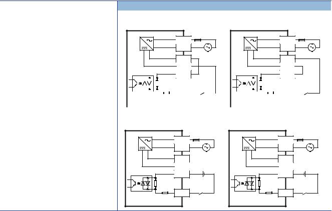
Item |
Specifications |
Input circuit configuration |
• When using service power supply |
Sink input wiring |
Source input wiring |
Fuse |
Fuse |
L |
L |
N |
N |
100 to 240 V AC |
100 to 240 V AC |
24V |
24V |
0V |
0V |
S/S |
S/S |
|
|
|
|
|
|
|
|
|
|
|
|
|
|
|
|
|
|
|
|
|
|
|
|
|
|
|
|
|
|
|
|
|
|
|
|
|
|
|
|
|
|
|
|
|
|
|
|
|
|
|
|
|
|
|
|
|
|
|
|
|
|
|
|
|
|
|
|
|
|
|
|
|
|
|
|
|
|
|
|
|
|
|
|
|
|
|
|
|
|
|
|
|
|
|
|
|
|
|
|
|
|
|
|
|
|
|
|
|
|
|
|
|
|
|
|
|
|
|
|
|
|
|
|
|
|
|
|
|
|
|
|
X |
|
|
|
|
|
|
|
|
|
|
|
|
|
|
|
|
|
|
X |
|
|
||
|
|
Input impedance |
|
|
|
|
|
Input impedance |
|
|
||||||||||||||||||||||||||||
|
|
|
|
|
|
|
|
|
|
|
|
|
|
|||||||||||||||||||||||||
|
|
|
|
|
|
|
|
|
|
|
|
|
|
|
|
|
|
|
|
|
|
|
|
|
|
|
|
|
|
|
|
|
|
|
|
|
|
|
|
|
|
|
|
|
|
|
|
|
|
|
|
|
|
|
|
|
|
|
|
|
|
|
|
|
|
|
|
|
|
|
|
|
|
|
|
|
|
• When using external power supply |
|
|
|
|
|
|
|
|
|
|
|
|
|
|
|
|
|
|
|
|
|
|||||||||||||||||
Sink input wiring |
|
|
|
|
|
Source input wiring |
|
|
|
|
||||||||||||||||||||||||||||
|
L |
Fuse |
|
L |
Fuse |
|
|
|
|
||
|
N |
|
|
N |
|
|
24V |
100 to 240 V AC |
|
24V |
100 to 240 V AC |
|
|
|
|
||
|
0V |
|
|
0V |
|
|
S/S |
|
|
S/S |
|
Input impedance |
X |
|
Input impedance |
X |
|
|
|
|
|
20 |
2 SPECIFICATIONS |
2.3 Input Specifications |

2.4 |
Output Specifications |
|
|||||||||||||
The CPU module output specifications are explained below. |
|||||||||||||||
Relay output |
|
|
|
|
|
|
|
|
|
|
|
|
|
||
|
|
|
|
|
|
|
|
|
|
|
|
2 |
|||
|
|
|
|
|
|
|
|
|
|
|
|
|
|
|
|
Item |
|
|
Output Specifications |
|
|
||||||||||
No. of output points |
|
FX5U-32MR/ |
16 points |
|
|||||||||||
|
|
|
|
|
|
|
|
|
|
|
|
|
|
|
|
|
|
FX5U-64MR/ |
32 points |
||||||||||||
|
|
|
|
|
|
|
|
|
|
|
|
|
|
|
|
|
|
FX5U-80MR/ |
40 points |
||||||||||||
|
|
|
|
|
|
|
|
|
|
|
|
|
|
|
|
Connection type |
|
|
Removable terminal block (M3 screws) |
||||||||||||
|
|
|
|
|
|
|
|
|
|
|
|
|
|
|
|
Output type |
|
|
Relay |
||||||||||||
|
|
|
|
|
|
|
|
|
|
|
|
|
|||
External power supply |
30 V DC or less |
||||||||||||||
|
|
|
240 V AC or less ("250 V AC or less" if not a CE, UL, cUL compliant item) |
||||||||||||
|
|
|
|
|
|
|
|
|
|
|
|
|
|
|
|
Max. load |
|
|
2 A/point |
||||||||||||
|
|
|
The total load current per common terminal should be the following value. |
||||||||||||
|
|
|
|
• 4 output points/common terminal: 8 A or less |
|||||||||||
|
|
|
|
• 8 output points/common terminal: 8 A or less |
|||||||||||
|
|
|
For details on the common, refer to Page 29 Interpretation of terminal block layout. |
||||||||||||
|
|
|
|
|
|
|
|
|
|
|
|
|
|
|
|
Min. load |
|
|
5 V DC, 2 mA (reference values) |
||||||||||||
|
|
|
|
|
|
|
|
|
|
|
|
|
|||
Open circuit leakage current |
|
||||||||||||||
|
|
|
|
|
|
|
|
|
|
|
|
|
|
|
|
Response time |
|
OFF ON |
Approx. 10 ms |
||||||||||||
|
|
|
|
|
|
|
|
|
|
|
|
|
|
|
|
|
|
ON OFF |
Approx. 10 ms |
||||||||||||
|
|
|
|
|
|
|
|
|
|
|
|
|
|
|
|
Insulation of circuit |
|
|
Mechanical insulation |
||||||||||||
|
|
|
|
|
|
|
|
|
|
|
|
|
|||
Indication of output operation |
|
LED is lit when output is on |
|||||||||||||
|
|
|
|
|
|
|
|
|
|
|
|
|
|
||
Output circuit configuration |
|
|
|
Load |
|
|
|
|
|
|
|
||||
|
|
|
|
|
|
|
|
|
|
||||||
|
|
|
|
|
|
Y |
|
|
|
|
|
||||
|
|
|
|
|
|
|
|
|
|
|
|
|
|
||
|
|
|
|
|
|
|
|
|
|
|
|
|
|
||
|
|
|
|
DC power supply |
|
|
|
|
|
|
|||||
|
|
|
|
|
|
|
|
|
|
||||||
|
|
|
|
|
|
|
|
|
|
|
|
|
|
||
|
|
|
|
|
|
|
|
|
COM |
|
|
|
|
|
|
|
|
|
|
Fuse |
|
|
|
|
|
|
|
|
|||
|
|
|
|
|
|
Load |
|
|
|
|
|
||||
|
|
|
|
Y |
|
|
|
|
|
||||||
|
|
|
|
|
|
|
|
|
|
|
|
|
|
||
|
|
|
|
AC power supply |
|
|
|
|
|
|
|||||
|
|
|
|
|
|
|
|
|
|
||||||
|
|
|
|
|
|
|
|
|
COM |
|
|
|
|||
|
|
|
|
Fuse |
|
|
|
|
|
||||||
|
|
|
|
|
|
|
|
|
|
|
|||||
|
|
|
A number is entered in the of [COM ]. |
||||||||||||
|
|
|
|
|
|
|
|
|
|
|
|
|
|
|
|
2 SPECIFICATIONS |
21 |
2.4 Output Specifications |

Transistor output
Item |
|
Output specifications |
No. of output points |
FX5U-32MT/ |
16 points |
|
|
|
|
FX5U-64MT/ |
32 points |
|
|
|
|
FX5U-80MT/ |
40 points |
|
|
|
Connection type |
|
Removable terminal block (M3 screws) |
|
|
|
Output type |
FX5U-MT/ES |
Transistor/sink output |
|
|
|
|
FX5U-MT/ESS |
Transistor/source output |
|
|
|
External power supply |
|
5 to 30 V DC |
|
|
|
Max. load |
|
0.5 A/point |
|
|
The total load current per common terminal should be the following value. |
•4 output points/common terminal: 0.8 A or less
•8 output points/common terminal: 1.6 A or less
|
|
|
For details on the common, refer to Page 29 Interpretation of terminal block layout. |
|
|
|
|
||
Open circuit leakage current |
0.1 mA or less/30 V DC |
|
||
|
|
|
|
|
Voltage drop when ON |
|
Y000 to Y003 |
1.0 V or less |
|
|
|
|
|
|
|
|
Y004 and subsequent |
1.5 V or less |
|
|
|
|
|
|
Response time |
|
Y000 to Y003 |
2.5 s or less/10 mA or more (5 to 24 V DC) |
|
|
|
|
|
|
|
|
Y004 and subsequent |
0.2 ms or less/200 mA or more (24 V DC) |
|
|
|
|
|
|
Insulation of circuit |
|
Photo-coupler insulation |
|
|
|
|
|
||
Indication of output operation |
LED is lit when output is on |
|
||
|
|
|
|
|
Output circuit configuration |
|
Sink output wiring |
Source output wiring |
|
|
|
|
||
Load |
Y |
|
|
Load |
Y |
|
|
|
|
|
|
|
|
||
DC power supply |
|
|
DC power supply |
|
|
||
Fuse |
COM |
|
|
Fuse |
+V |
|
|
|
|
|
|
|
|
||
A number is entered in the |
of [COM |
]. |
A number is entered in the |
of [+V |
]. |
||
2.5 Input/Output Derating Curve
The derating curve below shows the simultaneous ON ratio of available PLC inputs or outputs with respect to the ambient temperature. Use the PLC within the simultaneous input or output ON ratio range shown in the figure.
Derating curve
When service power supply or external power supply (24 V DC) is used for input circuits
Simultaneous ON ratio
100%
80%
applicable
50 55 Ambient temperature
22 |
2 SPECIFICATIONS |
2.5 Input/Output Derating Curve |

2.6 |
Performance Specifications |
|
||
|
|
|
|
|
Item |
|
Specification |
|
|
Control system |
|
Stored-program repetitive operation |
|
|
|
2 |
|||
|
|
|
||
Input/output control system |
Refresh system |
|||
|
|
(Direct access input/output allowed by specification of direct access input/output [DX, DY]) |
||
|
|
|
|
|
Programming |
Programming language |
Ladder diagram (LD), structured text (ST), function block diagram/ladder diagram (FBD/LD) |
|
|
specifications |
|
|
|
|
Programming extension function |
Function block (FB), structured ladder, label programming (local/global) |
|
||
|
|
|||
|
|
|
|
|
|
Constant scan |
0.2 to 2000 ms (can be set in 0.1 ms increments) |
|
|
|
|
|
|
|
|
Fixed cycle interrupt |
1 to 60000 ms (can be set in 1 ms increments) |
|
|
|
|
|
|
|
|
Timer performance specifications |
100 ms, 10 ms, 1 ms |
|
|
|
|
|
|
|
|
No. of program executions |
32 |
|
|
|
|
|
|
|
|
No. of FB files |
16 (Up to 15 for user) |
|
|
|
|
|
|
|
Operation |
Execution type |
Standby type, initial execution type, scan execution type, event execution type |
|
|
specifications |
|
|
|
|
Interrupt type |
Internal timer interrupt, input interruption, high-speed comparison match interrupt |
|
||
|
|
|||
|
|
|
|
|
Command |
LD X0 |
34 ns |
|
|
processing time |
|
|
|
|
MOV D0 D1 |
34 ns |
|
||
|
|
|||
|
|
|
|
|
Memory |
Program capacity |
64 k steps |
|
|
capacity |
|
(128 kbytes, flash memory) |
|
|
|
|
|
|
|
|
SD memory card |
Memory card capacity (SD/SDHC memory card: Max. 4 Gbytes) |
|
|
|
|
|
|
|
|
Device/label memory |
120 kbytes |
|
|
|
|
|
|
|
|
Data memory/standard ROM |
5 Mbytes |
|
|
|
|
|
|
|
Flash memory (Flash ROM) write count |
Maximum 20000 times |
|
||
|
|
|
|
|
File storage |
Device/label memory |
1 |
|
|
capacity |
|
|
|
|
Data memory |
P: 32, FB: 16 |
|
||
|
|
|||
|
P: No. of program files |
|
|
|
|
FB: No. of FB files |
|
|
|
|
|
|
|
|
|
SD Memory Card |
2 Gbytes: 511*1 |
|
|
|
|
4 Gbytes: 65534*1 |
|
|
Clock function |
Display data |
Year, month, day, hour, minute, second, day of week (leap year automatic detection) |
|
|
|
|
|
|
|
|
Precision |
-2.96 to +3.74 (TYP.+1.42) s/d (Ambient temperature: 0 (32 )) |
|
|
|
|
-3.18 to +3.74 (TYP.+1.50) s/d (Ambient temperature: 25 (77 )) |
|
|
|
|
-13.20 to +2.12 (TYP.-3.54) s/d (Ambient temperature: 55 (131 )) |
|
|
|
|
|
|
|
No. of input/ |
(1) No. of input/output points |
256 points or less |
|
|
output points |
|
|
|
|
(2) No. of remote I/O points |
384 points or less |
|
||
|
|
|||
|
|
|
|
|
|
Total No. of points of (1) and (2) |
512 points or less |
|
|
|
|
|
|
|
Power failure |
Retention method |
Large-capacity capacitor |
|
|
retention*2 |
|
|
|
|
Retention time |
10 days (Ambient temperature: 25 (77 )) |
|
||
|
|
|||
|
|
|
|
|
|
Data retained |
Clock data |
|
|
|
|
|
|
|
*1 The value listed above indicates the number of files stored in the root folder.
*2 Clock data is retained using the power accumulated in a large-capacity capacitor incorporated into the PLC. When voltage of the largecapacity capacitor drops, clock data is no longer accurately retained. The retention period of a fully charged capacitor (electricity is conducted across the PLC for at least 30 minutes) is 10 days (ambient temperature: 25 (77 )). How long the capacitor can hold the data depends on the operating ambient temperature. When the operating ambient temperature is high, the holding period is short.
2 SPECIFICATIONS |
23 |
2.6 Performance Specifications |

Number of device points
Item |
|
|
|
Base |
Max. number of points |
||
No. of user device |
Input relay (X) |
|
8 |
1024 points |
The total number of X and Y assigned to input/output points is up to |
||
points |
|
|
|
|
|
256 points. |
|
Output relay (Y) |
|
8 |
1024 points |
||||
|
|
|
|||||
|
|
|
|
|
|
||
|
Internal relay (M) |
|
10 |
32768 points (can be changed with parameter)*1 |
|||
|
Latch relay (L) |
|
10 |
32768 points (can be changed with parameter)*1 |
|||
|
Link relay (B) |
|
16 |
32768 points (can be changed with parameter)*1 |
|||
|
Annunciator (F) |
|
10 |
32768 points (can be changed with parameter)*1 |
|||
|
Link special relay (SB) |
16 |
32768 points (can be changed with parameter)*1 |
||||
|
Step relay (S) |
|
10 |
4096 points (fixed) |
|||
|
|
|
|
|
|
||
|
Timer system |
|
Timer (T) |
10 |
1024 points (can be changed with parameter)*1 |
||
|
Accumulation |
|
Accumulation timer |
10 |
1024 points (can be changed with parameter)*1 |
||
|
timer system |
|
(ST) |
|
|
|
|
|
|
|
|
|
|
||
|
Counter |
|
Counter (C) |
10 |
1024 points (can be changed with parameter)*1 |
||
|
system |
|
|
|
|
||
|
|
Long counter (LC) |
10 |
1024 points (can be changed with parameter)*1 |
|||
|
Data register (D) |
|
10 |
8000 points (can be changed with parameter)*1 |
|||
|
Link register (W) |
|
16 |
32768 points (can be changed with parameter)*1 |
|||
|
Link special register (SW) |
16 |
32768 points (can be changed with parameter)*1 |
||||
No. of system device |
Special relay (SM) |
10 |
10000 points (fixed) |
||||
points |
|
|
|
|
|
|
|
Special register (SD) |
10 |
12000 points (fixed) |
|||||
|
|||||||
|
|
|
|
||||
Module access device |
Intelligent function module device |
10 |
65536 points (designated by U\G) |
||||
|
|
|
|
|
|||
No. of index register |
Index register (Z)*2 |
10 |
24 points |
|
|||
points |
|
|
|
|
|||
Long index register (LZ)*2 |
10 |
12 points |
|
||||
No. of file register |
File register (R) |
|
10 |
32768 points (can be changed with parameter)*1 |
|||
points |
|
|
|
|
|
|
|
|
|
|
|
|
|||
No. of nesting points |
Nesting (N) |
|
10 |
15 points (fixed) |
|||
|
|
|
|
|
|
||
No. of pointer points |
Pointer (P) |
|
10 |
4096 points |
|
||
|
|
|
|
||||
|
Interrupt pointer (I) |
10 |
178 points (fixed) |
||||
|
|
|
|
|
|
||
Others |
Decimal |
|
Signed |
|
16 bits: -32768 to +32767, 32 bits: -2147483648 to +2147483647 |
||
|
constant (K) |
|
|
|
|
|
|
|
|
Unsigned |
|
16 bits: 0 to 65535, 32 bits: 0 to 4294967295 |
|||
|
|
|
|||||
|
|
|
|
|
|
||
|
Hexadecimal constant (H) |
|
16 bits: 0 to FFFF, 32 bits: 0 to FFFFFFFF |
||||
|
|
|
|
|
|
||
|
Real constant |
|
Single precision |
|
E-3.40282347+38 to E-1.17549435-38, 0, E1.17549435-38 to E3.40282347+38 |
||
|
(E) |
|
|
|
|
|
|
|
|
|
|
|
|
|
|
|
Character string |
|
|
Shift-JIS code max. 255 single-byte characters (256 including NULL) |
|||
|
|
|
|
|
|
|
|
*1 Can be changed with parameters within the capacity range of the CPU built-in memory. *2 Total of the index register (Z) and long index register (LZ) is maximum 24 words.
24 |
2 SPECIFICATIONS |
2.6 Performance Specifications |

2.7 Built-in Analog Specifications
The analog input/output specifications of the built-in analog function are explained below.
For details on the analog built-in function, refer to MELSEC iQ-F FX5 User's Manual (Analog Control).
Analog input |
|
|
2 |
|
|
|
|
||
Item |
|
Specifications |
|
|
Analog input points |
|
2 points (2 channels) |
|
|
|
|
|
|
|
Analog input |
Voltage |
0 to 10 V DC (input resistance 115.7 k ) |
||
|
|
|
|
|
Digital output |
|
Unsigned 12-bit binary |
||
|
|
|
|
|
I/O characteristics, Maximum resolution |
Digital output value |
0 to 4000 |
||
|
|
|
|
|
|
Maximum resolution |
2.5 mV |
||
|
|
|
|
|
Accuracy |
Ambient temperature |
Within 0.5% ( 20 digit*1) |
||
(Accuracy in respect to maximum digital |
25 5 (77 41 ) |
|
|
|
output value) |
|
|
||
Ambient temperature |
Within 1.0% ( 40 digit*1) |
|
||
|
0 to 55 (32 to 131 ) |
|
|
|
|
|
|
|
|
Conversion speed |
|
30 s /channels (data refreshed every operation cycle) |
||
|
|
|
|
|
Absolute maximum input |
|
-0.5 V, +15 V |
||
|
|
|
|
|
Insulation method |
|
Inside the PLC and the analog input circuit are not insulated. Between input terminals |
||
|
|
(channels) is not insulated. |
||
|
|
|
|
|
Occupied points |
|
0 points (does not pertain to the max. No. of input/output points of the PLC.) |
||
|
|
|
|
|
Terminal block used |
|
European-type terminal block |
||
|
|
|
|
|
*1 "Digit" refers to digital values. |
|
|
|
|
Analog output |
|
|
|
|
|
|
|
||
Item |
|
Specifications |
|
|
Analog output points |
|
1 points (1 channels) |
|
|
|
|
|
|
|
Digital input |
|
Unsigned 12-bit binary |
||
|
|
|
|
|
Analog output |
Voltage |
0 to 10 V DC (external load resistance 2 k to 1 M ) |
||
|
|
|
|
|
I/O characteristics, Maximum resolution*1 |
Digital input value |
0 to 4000 |
|
|
|
Maximum resolution |
2.5 mV |
||
|
|
|
|
|
Accuracy*2 |
Ambient temperature |
Within 0.5% ( 20 digit*3) |
||
(Accuracy in respect to maximum analog |
25 5 (77 41 ) |
|
|
|
output value) |
|
|
||
Ambient temperature |
Within 1.0% ( 40 digit*3) |
|
||
|
0 to 55 (32 to 131 ) |
|
|
|
|
|
|
|
|
Conversion speed |
|
30 s (data refreshed every operation cycle) |
||
|
|
|
|
|
Insulation method |
|
Inside the PLC and the analog output circuit are not insulated. |
||
|
|
|
|
|
Occupied points |
|
0 points (does not pertain to the max. No. of input/output points of the PLC.) |
||
|
|
|
|
|
Terminal block used |
|
European-type terminal block |
||
|
|
|
|
|
*1 There is a dead band near 0 V output, which is an area where some analog output values do not reflect digital input values.
*2 External load resistance is set to 2 k when shipped from the factory. Thus, output voltage will increase somewhat if the resistance is set higher than 2 k . When the resistance is 1 M , output voltage increases maximum 2%.
*3 "Digit" refers to digital values.
2 SPECIFICATIONS |
25 |
2.7 Built-in Analog Specifications |

2.8 Communication Specifications
The built-in Ethernet and built-in RS-485 communication specifications are as explained below.
Built-in Ethernet communication
For details of built-in Ethernet communication, refer to the following.MELSEC iQ-F FX5 User's Manual (Ethernet Communication)MELSEC iQ-F FX5 User's Manual (SLMP)
Item |
|
Specifications |
Data transmission speed |
|
100/10 Mbps |
|
|
|
Communication mode |
|
Full-duplex (FDX) / Half-duplex (HDX) |
|
|
|
Interface |
|
RJ45 connector |
|
|
|
Transmission method |
|
Base band |
|
|
|
Maximum segment length (The distance between hub and node) |
100 m (328'1") |
|
|
|
|
Cascade connection |
100BASE-TX |
Cascade connection max. 2 stages*1 |
|
10BASE-T |
Cascade connection max. 4 stages*1 |
Protocol type |
|
MELSOFT connection |
|
|
|
|
|
SLMP (3E frame) |
|
|
|
|
|
Socket communication |
|
|
|
|
|
Predefined protocol support |
|
|
|
Number of simultaneously open connections allowed |
Total of 8 for socket communication, MELSOFT connection, SLMP, and Predefined |
|
|
|
protocol support |
|
|
(Up to 8 external devices can access one CPU module at the same time.) |
|
|
|
Insulation method |
|
Pulse transformer insulation |
|
|
|
Cable used*2 |
For 100BASE-TX connection |
Ethernet standard-compatible cable, category 5 or higher (STP cable) |
|
For 10BASE-T connection |
Ethernet standard-compatible cable, category 3 or higher (STP cable) |
|
|
|
*1 Number of stages that can be connected when a repeater hub is used. When a switching hub is used, check the specifications of the switching hub used.
*2 A straight cable can be used. If a personal computer or GOT and CPU module are directly connected a cross cable can be used.
Built-in RS-485 communication
For details of built-in RS-485 communication, refer to the following.MELSEC iQ-F FX5 User's Manual (Serial Communication)MELSEC iQ-F FX5 User's Manual (MODBUS Communication)
Item |
Specifications |
Transmission standards |
Conforms to RS-485/RS-422 specifications |
|
|
Data transmission speed |
Max. 115.2 kbps |
|
|
Communication method |
Full-duplex (FDX) / Half-duplex (HDX) |
|
|
Maximum total extension distance |
50 m (164'0") |
|
|
Protocol type |
MELSOFT connection |
|
|
|
Non-protocol communication |
|
|
|
MELSEC Communication protocol (3C/4C frames) |
|
|
|
MODBUS RTU |
|
|
|
Predefined protocol support |
|
|
|
Inverter communication |
|
|
|
N:N network |
|
|
Insulation method |
Not insulated |
|
|
Terminal resistors |
Built-in (OPEN/110 /330 ) |
|
|
Terminal block used |
European-type terminal block |
|
|
26 |
2 SPECIFICATIONS |
2.8 Communication Specifications |
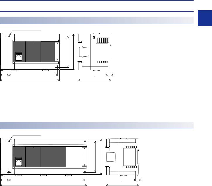
2.9 |
External Dimensions |
|
CPU module |
|
|
FX5U-32M |
2 |
|
|
||
2- 4.5 mounting holes |
Unit: mm (inches) |
|
|
80 (3.15") (mounting hole pitch) |
90 (3.55") |
22 |
W1 |
8 (0.32") |
(0.87") |
W |
83 (3.27") |
|
||
Model |
W |
W1 (mounting hole pitch) |
Mass (weight) |
FX5U-32M |
150 mm (5.91") |
123 mm (4.85") |
Approx. 0.65 kg (1.43 lbs) |
|
|
|
|
• Exterior color
Main body: Munsell 0.6B7.6/0.2
• Accessories
Dust proof protection sheet Manual supplied with product
FX5U-64M, FX5U-80M
4- 4.5 mounting holes |
Unit: mm (inches) |
22 |
W1 |
(0.87") |
W |
|
80 (3.15") (mounting hole pitch) |
90 (3.55") |
|
8 (0.32") |
|
83 (3.27") |
Model |
|
W |
W1 (mounting hole pitch) |
Mass (weight) |
FX5U-64M |
|
220 mm (8.67") |
193 mm (7.6") |
Approx. 1.0 kg (2.2 lbs) |
|
|
|
|
|
FX5U-80M |
|
285 mm (11.23") |
258 mm (10.16") |
Approx. 1.2 kg (2.64 lbs) |
|
|
|
|
|
• Exterior color |
|
|
|
|
Main body: |
Munsell 0.6B7.6/0.2 |
|
|
|
• Accessories |
|
|
|
|
Dust proof protection sheet
Manual supplied with product
2 SPECIFICATIONS |
27 |
2.9 External Dimensions |

2.10 Terminal Layout
Built-in RS-485 terminal
European type terminal block
5 poles
RDA (RXD+)
RDB (RXD-)
SDA (TXD+)
SDB (TXD-)
SG (GND)
Built-in analog terminal
European type terminal block
5 poles
V1+ V2+ V- |
|
V+ V- |
|
|
|
Analog |
Analog |
|
input |
|
output |
Built-in Ethernet connector
|
|
|
|
|
|
|
|
|
|
|
|
Pin |
Signal name |
|
|
|
|
|
|
|
|
|
|
|
|
||
|
|
|
|
|
|
|
|
|
|
|
|
1 |
TD+ |
|
|
|
|
|
|
|
|
|
|
|
|
||
|
|
|
|
|
|
|
|
|
|
|
|
2 |
TD- |
|
|
|
|
|
|
|
|
|
|
|
|
||
|
|
|
|
|
|
|
|
|
|
|
|
||
8 |
|
|
|
|
|
1 |
|
|
3 |
RD+ |
|||
|
|
|
|
|
|
|
|
|
|
|
|
4 |
Not used |
|
|
|
|
|
|
|
|
|
|
|
|
5 |
Not used |
|
|
|
|
|
|
|
|
|
|
|
|
6 |
RD- |
|
|
|
|
|
|
|
|
|
|
|
|
7 |
Not used |
|
|
|
|
|
|
|
|
|
|
|
|
8 |
Not used |
28 |
2 SPECIFICATIONS |
2.10 Terminal Layout |
Loading...