


FR-A8AP
Table of contents
 Loading...
INVERTER
Plug-in option
INSTRUCTION MANUAL
PRE-OPERATION INSTRUCTIONS
1
INSTALLATION AND WIRING
2
ENCODER SPECIFICATIONS AND
PARAMETER SETTINGS
3
ORIENTATION CONTROL
4
ENCODER FEEDBACK CONTROL
5
VECTOR CONTROL
6
FR-A8AP
Orientation control
Encoder feedback control
Vector control
3
Thank you for choosing this Mitsubishi inverter plug-in option.
This Instruction Manual provides handling information and precautions for use of the equipment. Incorrect handling might cause an unexpected
fault. Before using this inverter, always read this Instruction Manual carefully to use the equipment to its optimum performance.
Please forward this Instruction Manual to the end user.
Electric Shock Prevention
Injury Prevention
Safety instructions
Do not attempt to install, operate, maintain or inspect the product until you have read through this Instruction Manual and appended
documents carefully and can use the equipment correctly. Do not use this product until you have a full knowledge of the equipment, safety
information and instructions. In this Instruction Manual, the safety instruction levels are classified into "WARNING" and "CAUTION".
Incorrect handling may cause hazardous conditions, resulting in death or severe injury.
Incorrect handling may cause hazardous conditions, resulting in medium or slight injury, or may cause only material
damage.
The level may even lead to a serious consequence according to conditions. Both instruction levels must be followed
because these are important to personal safety.
Warning
While the inverter power is ON, do not open the front cover or the wiring cover. Do not run the inverter with the front cover or the wiring cover removed. Otherwise
you may access the exposed high voltage terminals or the charging part of the circuitry and get an electric shock.
Do not remove the inverter front cover even if the power supply is disconnected. The only exception for this would be when performing wiring and periodic
inspection. You may accidentally touch the charged inverter circuits and get an electric shock.
Before wiring or inspection, LED indication of the inverter unit operation panel must be switched OFF. Any person who is involved in wiring or inspection shall wait
for at least 10 minutes after the power supply has been switched OFF and check that there is no residual voltage using a tester or the like. For a short time after the
power-OFF, a high voltage remains in the smoothing capacitor, and it is dangerous.
Any person who is involved in wiring or inspection of this equipment shall be fully competent to do the work.
The plug-in option must be installed before wiring. Otherwise you may get an electric shock or be injured.
Do not touch the plug-in option or handle the cables with wet hands. Otherwise you may get an electric shock.
Do not subject the cables to scratches, excessive stress, heavy loads or pinching. Otherwise you may get an electric shock.
Caution
The voltage applied to each terminal must be the ones specified in the Instruction Manual. Otherwise a burst, damage, etc. may occur.
The cables must be connected to the correct terminals. Otherwise a burst, damage, etc. may occur.
The polarity (+ and -) must be correct. Otherwise a burst or damage may occur.
While power is ON or for some time after power OFF, do not touch the inverter as it will be extremely hot. Touching these devices may cause a burn.
Warning
Caution
Caution
4
Additional Instructions
The following instructions must be also followed. If the product is handled incorrectly, it may cause unexpected fault, an injury, or an electric
shock.
Caution
Transportation and mounting
Do not install or operate the plug-in option if it is damaged or has parts missing.
Do not stand or rest heavy objects on the product.
The mounting orientation must be correct.
Foreign conductive objects must be prevented from entering the inverter. That includes screws and metal fragments or other flammable substance such as oil.
If halogen-based materials (fluorine, chlorine, bromine, iodine, etc.) infiltrate into a Mitsubishi product, the product will be damaged. Halogen-based materials are
often included in fumigant, which is used to sterilize or disinfest wooden packages. When packaging, prevent residual fumigant components from being infiltrated
into Mitsubishi products, or use an alternative sterilization or disinfection method (heat disinfection, etc.) for packaging. Sterilization of disinfection of wooden
package should also be performed before packaging the product.
Trial run
Before starting operation, each parameter must be confirmed and adjusted. A failure to do so may cause some machines to make unexpected motions.
Warning
Usage
Do not modify the equipment.
Do not perform parts removal which is not instructed in this manual. Doing so may lead to fault or damage of the product.
Caution
Usage
When parameter clear or all parameter clear is performed, the required parameters must be set again before starting operations. Because all parameters return to
their initial values.
Static electricity in your body must be discharged before you touch the product.
Maintenance, inspection and parts replacement
Do not carry out a megger (insulation resistance) test.
Disposal
The inverter must be treated as industrial waste.
General instruction
Many of the diagrams and drawings in this Instruction Manual show the inverter without a cover or partially open for explanation. Never operate the inverter in this
manner. The cover must be reinstalled and the instructions in the Instruction Manual must be followed when oper ating the inverter.

5
— CONTENTS —
1 PRE-OPERATION INSTRUCTIONS 7
1.1 Unpacking and product confirmation ..............................................................................................7
1.2 Component names.............................................................................................................................8
2 INSTALLATION AND WIRING 9
2.1 Pre-installation instructions .............................................................................................................9
2.2 Installation procedure .......................................................................................................................9
2.3 Encoder specification / terminating resistor switch setting........................................................12
2.4 Wiring ................................................................................................................................................14
2.5 Encoder cables dedicated to Mitsubishi motors ..........................................................................17
2.6 Terminals ..........................................................................................................................................18
3 ENCODER SPECIFICATIONS AND PARAMETER SETTINGS 19
3.1 Encoder.............................................................................................................................................19
3.2 Parameter setting.............................................................................................................................21
3.2.1 Parameter for encoder.................................................................................................................................. 21
3.2.2 Parameter settings for the motor under vector control.................................................................................22
4 ORIENTATION CONTROL 23
4.1 Wiring example ................................................................................................................................23
4.2 Terminals ..........................................................................................................................................25
4.3 Specifications...................................................................................................................................26

6
5 ENCODER FEEDBACK CONTROL 27
5.1 Wiring examples ..............................................................................................................................27
5.2 Specifications...................................................................................................................................28
6 VECTOR CONTROL 29
6.1 Wiring examples ..............................................................................................................................29
6.2 Specifications...................................................................................................................................33
PRE-OPERATION INSTRUCTIONS
7
1
1 PRE-OPERATION INSTRUCTIONS
1.1 Unpacking and product confirmation
Take the plug-in option out of the package, check the product name, and confirm that the product is as you ordered and intact.
This product is a plug-in option dedicated for the FR-A800 series.
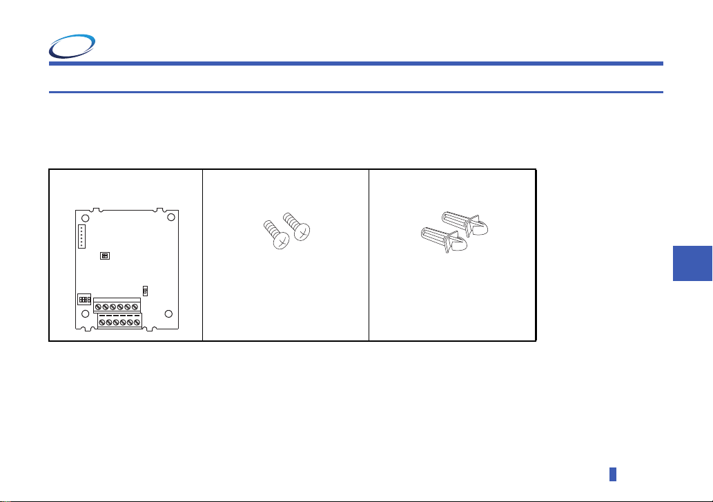
Product confirmation
Check the enclosed items.
Plug-in option
...............................................1
Mounting screw (M3 × 8 mm)
.....................2 (Refer to page 9.)
Spacer
....................2 (Refer to
page 9.)
1
2
3
4
O
N
1
2
O
N
SW2
SW3
SW1
8
PRE-OPERATION INSTRUCTIONS
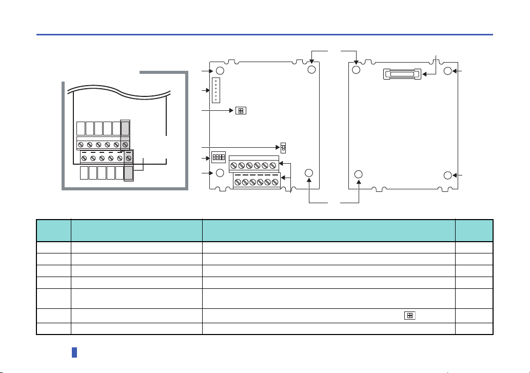
1.2 Component names
Symbol
Name Description
Refer to
page
a Mounting hole Fixes the option to the inverter with screws, or installs spacers. 9
b Terminal block Connects to the encoder. 14
c
Encoder type selection switch (SW3)
Switches the encoder type (differential line driver/ complementary). 12
d CON2 connector Not used. ―
e
Terminating resistor selection switch
(SW1)
Switches ON or OFF the internal terminating resistor. 12
f
Switch for manufacturer setting (SW2)
D
o not change the initially-set status. (Switches 1 and 2 are OFF .)
―
g Connector Connects to the option connector of the inverter. 9
Front view
Rear view
Terminal layout
PA2
PB2
PZ2
SD
SD
PO
PA1
PB1
PZ1
PG
PG
PIN
PIN and PO
are not used.
1
2
O
N
SW2
SW3
SW1
(a)
(g)
(a)
(b)
(a)
(a)
(a)
(a)
(e)
(d)
(f)
(c)
1
2
3
4
O
N
1
2
O
N
INSTALLATION AND WIRING
9
2
2 INSTALLATION AND WIRING
2.1 Pre-installation instructions
Check that the inverter's input power and the control circuit power are both OFF.
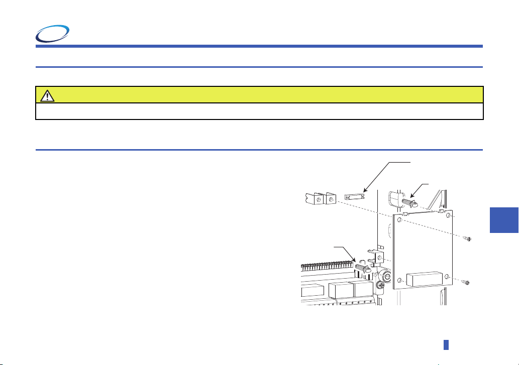
2.2 Installation procedure
(1) Remove the inverter front cover. (Refer to Chapter 2 of the
Instruction Manual (Detailed) of the inverter for details on how to
remove the front cover.)
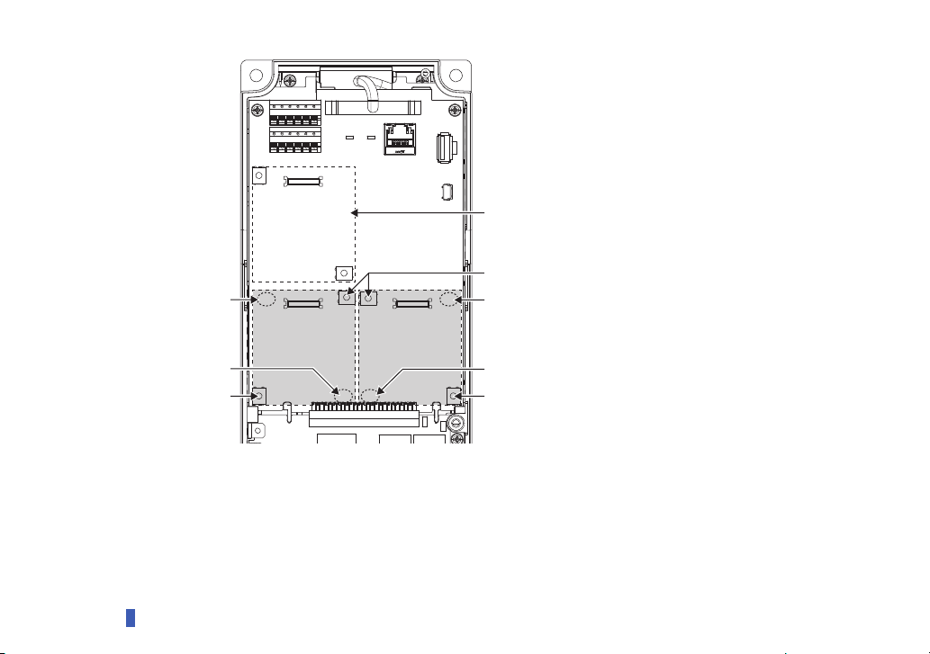
(2) For the two mounting holes (as shown in the next page) that will not
be tightened with mounting screws, insert spacers.
(3) Fit the connector of the plug-in option along the guide of the
connector on the inverter, and insert the plug-in option as far as it
goes. (Insert it to the inverter option connector 1 or 2.)
(4) Fit the two locations, the left and right, of the plug-in option securely
to the inverter unit by screwing in the supplied mounting screws
(tightening torque 0.33 N·m to 0.40 N·m). If the screw holes do not
line up, the connector may not be inserted deep enough. Check the
connector.
Caution
Do not mount or remove the plug-in option while the input power is ON. Doing so may damage the inverter or plug-in option.
To avoid damage due to static electricity, static electricity in your body must be discharged before you touch the product.
Spacer
Spacer
Inverter side
option connector
10
INSTALLATION AND WIRING
Spacer
Spacer
Mounting screw
Do not insert the plug-in option to the connector 3.
Mounting screw
Spacer
Spacer
Mounting screw
Connector 1Connector 2
Connector 3
Insertion positions for screws and spacers
INSTALLATION AND WIRING
11
2
NOTE
• Caution must be taken of mounting screws falling off when removing and mounting the plug-in option.
• Only one type of option per inverter may be used. When multiple options are mounted, priority is given to option
connectors 1, 2 and 3 on the inverter in this order, and options having a lower priority do not function. (For the
positions of the option connectors 1 to 3, refer to page 10.)
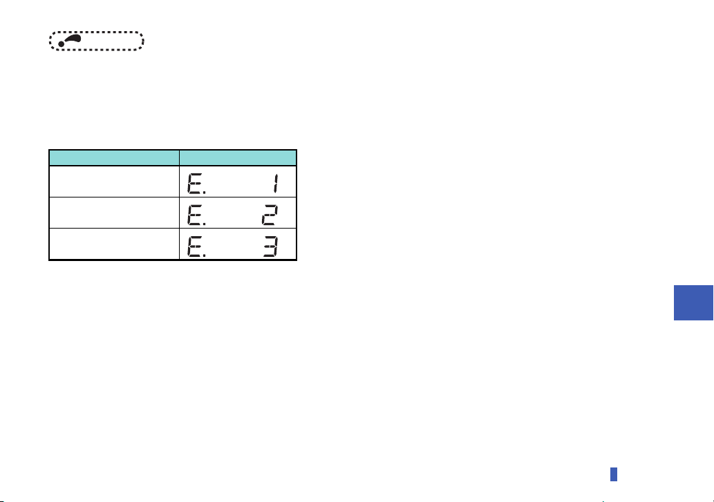
• When the inverter cannot recognize that the option unit is mounted due to improper installation, etc., the protective
function (E.1 to E.3) is displayed. A different indication will appear according to the mounted position (option connector
1 to 3).
• When removing the plug-in option, remove the two screws on the left and right, then pull it straight out. Pressure
applied to the connector and to the option board may break the option.
Mounted position Fault indication
Option connector 1
Option connector 2
Option connector 3
12
INSTALLATION AND WIRING
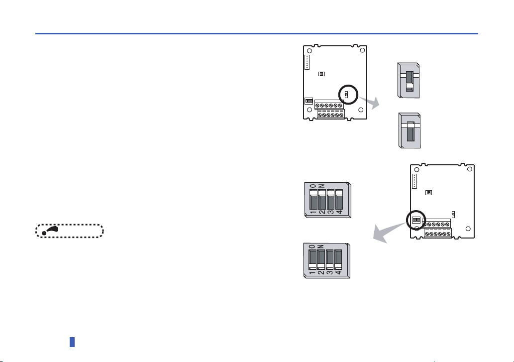
2.3 Encoder specification / terminating resistor switch setting
Encoder specification selection switch (SW3)
Select either differential line driver or complementary.
It is initially set to the differential line driver. Switch its position according
to output circuit.
Terminating resistor selection switch (SW1)
Select "ON"/"OFF" of the internal terminating resistor. Set the switch to
"ON" (initial status) when an encoder output type is differential line driver
and set to "OFF" when complementary.
ON : with internal terminating resistor (initial setting status)
OFF : without internal terminating resistor
NOTE
• Set all switches to the same setting ("ON"/ "OFF").
• If the encoder output type is differential line driver, set the
terminating resistor switch to the "OFF" position when
sharing the same encoder with other unit (CNC
(computerized numerical controller), etc) or a terminating
resistor is connected to other unit.
Complementary
Differential line driver
(initial status)
1
2
O
N
SW2
SW3
SW1
1
2
3
4
O
N
Internal terminating
resistor-ON
(initial status)
Internal terminating
resistor-OFF
1
2
O
N
SW2
SW3
SW1
1
2
3
4
O
N
Loading...