


LEVEL 3 SERVICE
FA9M030110
GALAXY
ASTRAL
GEO
GEO WAP
(DUAL BAND)
R |
V |
A : Création P. LE SIGNOR |
05/99 |
Rédigé par |
Verifié par |
Approuvé par |
E |
R |
B : Modif MTS 2.0 english |
06/99 |
Written by |
Checked by |
Approuved by |
V |
S |
C : Ajout ASTRAL et GEO |
07/99 |
X. GLASSON |
B. LEGORGEU |
G. LEBASTARD |
I |
I |
D : Modif Testmode |
02/00 |
|
|
|
|
|
software |
|
|
|
|
S |
O |
E : Ajout GEO WAP |
04/00 |
|
|
|
I |
N |
|
|
|
|
|
O |
S |
|
|
|
|
|
N |
|
|
|
|
|
|
S |
|
|
|
|
|
|
Mitsubishi Electric Telecom Europe SA |
Version E |
ZA le Piquet, 35370 Etrelles |
Date: 04/00 |
Phone: +33 2 99 75 71 00 |
|
Fax: +33 2 99 75 71 47 |
|

TABLE OF CONTENTS |
|
||||
1 |
Block Diagram |
3 |
|||
1.1 |
Schematic |
|
3 |
||
1.2 |
Description of Block Diagram. |
3 |
|||
|
1.2.1 |
IC300 |
One-C (VWS22100). |
3 |
|
|
1.2.2 |
IC100 |
IPD (Rohm BH6070KU). |
3 |
|
|
1.2.3 |
IC600 |
RF-IC (Hitachi HD155121FEB). |
3 |
|
|
1.2.4 |
Memory system. |
4 |
||
|
1.2.5 |
System Clock. |
4 |
||
2. |
Battery management. |
5 |
|||
2.1 |
Block Diagram. |
5 |
|||
2.2 |
Description. |
|
5 |
||
2.3 |
Charging process. |
7 |
|||
2.4 |
Main characteristics. |
8 |
|||
2.5 |
Autonomy Control. |
8 |
|||
2.6 |
Power on. |
|
9 |
||
2.7 |
Power off. |
|
10 |
||
2.8 |
Real Time Clock (Geo and Geo WAP) |
10 |
|||
3. |
RF Section. |
|
11 |
||
3.1 |
Frequency range. |
11 |
|||
|
3.1.1 |
E-GSM Frequency : |
11 |
||
|
3.1.2 |
DCS Frequency : |
11 |
||
3.2 |
Synthetiser Circuit Description. |
12 |
|||
3.3 |
RF Block Diagram. |
13 |
|||
3.4 |
Reception |
|
14 |
||
|
3.4.1 |
Reception Block Diagram. |
14 |
||
|
3.4.2 Description of Reception Block Diagram |
14 |
|||
3.5 |
Transmission. |
|
15 |
||
|
3.5.1 |
Transmission Block Diagram. |
15 |
||
|
3.5.2 |
Description of Transmission Block Diagram. |
15 |
||
|
3.5.3 |
Power Control. |
16 |
||
4. |
Speech coder. |
17 |
|||
4.1 |
Full rate / Half rate / Enhanced full rate. |
17 |
|||
5.Analogue Audio.
Mitsubishi Electric Telecom Europe SA ZA le Piquet, 35370 Etrelles
Phone: +33 2 99 75 71 00 Fax: +33 2 99 75 71 47
19
Version E
Date: 04/00
1/29

|
|
|
|
Level 3 Service Manual |
|
|
|
|
GALAXY ASTRAL GEO GEO WAP |
5.1 |
Buzzer. |
19 |
||
5.2 |
Speaker (RX audio). |
19 |
||
5.3 |
Micro (TX audio). |
19 |
||
6. |
Testmode Software. |
20 |
||
6.1 |
Equipment installation |
20 |
||
6.2 |
Software (MTS) installation |
21 |
||
|
6.2.1 |
Simple Setup : |
21 |
|
|
6.2.2 |
Complete Setup : |
21 |
|
6.3 |
Software (MTS) description |
22 |
||
|
6.3.1 MMI Testmode interface : description of functions |
22 |
||
7. |
Basic Adjustment. |
27 |
||
7.1 |
Power Adjustment. |
27 |
||
7.2 |
RSSI control. |
28 |
||
8. |
Software Version . |
28 |
||
9. |
Trouble Shooting help guide |
29 |
||
Version E |
Mitsubishi Electric Telecom Europe SA |
||
Date: 04/00 |
ZA le Piquet 35370 Etrelles |
||
2/29 |
|
Phone: +33 |
2 99 75 71 00 |
|
Fax: + 33 |
2 99 75 71 47 |
|

Level 3 Service Manual
GALAXY ASTRAL GEO GEO WAP
1 Block Diagram
1.1Schematic
Parallele bus
Serial bus
1.2Description of Block Diagram.
1.2.1IC300 One-C (VWS22100).
IC300 includes in one same chipset Base Band part, DSP, CPU, A/D, D/A converters, TDMA framecounters, a TX GMSK modulator, a TX power ramping circuit, RX filters. IC300 carries out the management of the battery charging, and of the audio part. It interfaces with the radio frequency part.
1.2.2IC100 IPD (Rohm BH6070KU).
IC100 provides the different powers supplies to RFBB board : 2.8RTC, PSTCXO, 2.8VANA, PSSYN, 2.8VAUD, VBAT, 3.6VB, 2.8VD, 5VSIM. The management of the battery charging is carried out by internal circuit of IC100.
1.2.3IC600 RF-IC (Hitachi HD155121FEB).
Transceiver IC for E-GSM and DCS Dual Band cellular systems.
Mitsubishi Electric Telecom Europe SA ZA le Piquet, 35370 Etrelles
Phone: +33 2 99 75 71 00 Fax: + 33 2 99 75 71 47
Version E
Date: 04/00
3/29

Level 3 Service Manual
GALAXY ASTRAL GEO GEO WAP
1.2.4Memory system.
Location |
Type |
Data |
Size |
Size |
|
|
|
Galaxy Astral Geo |
Geo WAP |
IC201 |
Flash ROM |
CPUprogram code |
1 MB |
2MB |
IC202 |
RAM |
Data for CPU work |
128 kB |
128 kB |
IC203 |
EEPROM |
Data user, RF adj. |
64 kB |
128 kB |
1.2.5System Clock.
The system clock for the telephone is 13 MHz TCXO, generated by X600. It is processed in IC300 to provide serial clock for LCD, EEPROM, and IC100. The clock is buffered in IC300 One-C, and then fed to IC100 IPD as “CPU CLK ” . It is available on pin 56 of IC100.
During Stand-By mode, the system clock is not managed from X600 TCXO but from X300 ( “slow clock ” at 32.768 kHz).
Version E |
Mitsubishi Electric Telecom Europe SA |
||
Date: 04/00 |
ZA le Piquet 35370 Etrelles |
||
4/29 |
|
Phone: +33 |
2 99 75 71 00 |
|
Fax: + 33 |
2 99 75 71 47 |
|
Level 3 Service Manual
GALAXY ASTRAL GEO GEO WAP
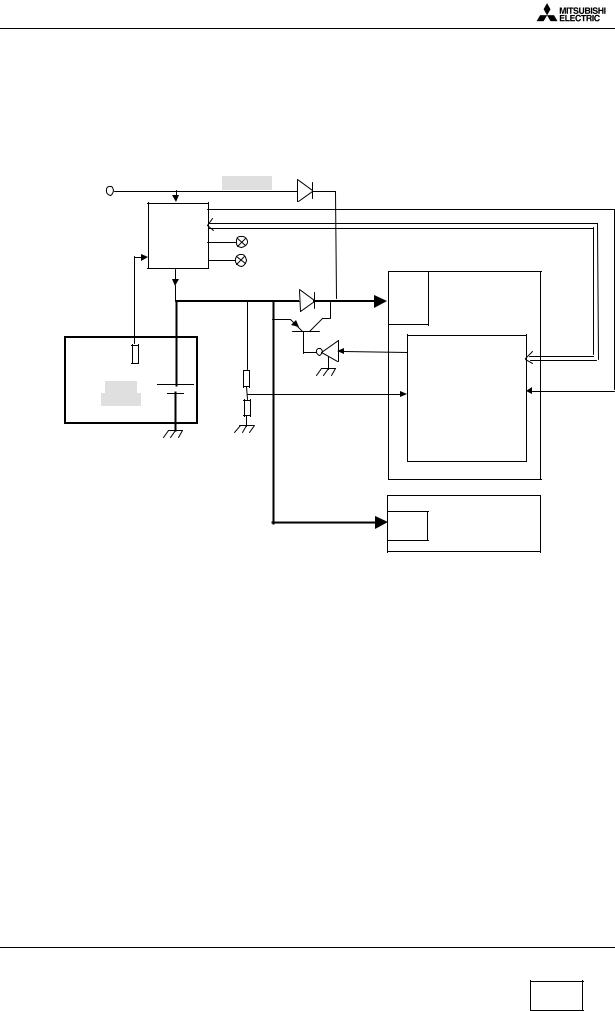
2.Battery management.
2.1Block Diagram.
EXPS: |
|
5,8V nominal |
|
|
|
|
|
|
|
AC/DC |
|
|
CHGERR |
|
CLA |
IPD |
|
SPI interface |
|
DTC |
charger |
|
|
|
HF kit |
Green led |
|
|
|
|
|
Red led |
|
|
|
I charge |
|
|
Base Band |
|
|
3,8V nominal |
IPD |
|
|
|
|
regulators |
|
TH |
|
|
|
|
|
+ |
|
|
|
thermistor |
|
|
BYPASS |
One-C |
|
|
GPIO9 |
||
NIMH |
|
BLEV |
AUX_IN0 |
GPIO10 |
900mAh |
|
|
|
|
|
|
|
regulators |
RADIO |
2.2 Description.
The battery is NiMH 900mAh, 3.8 V nominal for Galaxy, Astral and Geo
External power supply for charging (EXPS) comes from the DC jack at the bottom side of the mobile (AC/DC, CLA, DTC or H/F Kit). This power supply is 5.8 V nominal. Battery presence and battery type information are accessible in CHGM IPD register. If a Li-ion battery is detect, the software considers that the battery is absent.
The battery temperature information (TH) is given by thresholds in IPD CHGM register. This information are used only for charge control.
The battery level information is accessible in an A/D converter in One-C. It is also available in CHGM IPD register , these information are given by range only for range control.
External power supply (EXPS) presence information are accessible in CHGD IPD register. As described in the drawing above, the power supply for Base Band (IC300) comes from EXPS when it is present because EXPS level (5.8 V) is always greater than battery voltage. On the contrary, power supply for radio always comes from the battery.
The serial diode between battery and One-C (IC300) can be bypassed by software to reduce voltage headroom. Bypass is Activated when battery is less than 3.45 V.
Mitsubishi Electric Telecom Europe SA ZA le Piquet, 35370 Etrelles
Phone: +33 2 99 75 71 00 Fax: + 33 2 99 75 71 47
Version E
Date: 04/00
5/29

Level 3 Service Manual
GALAXY ASTRAL GEO GEO WAP
Version E |
Mitsubishi Electric Telecom Europe SA |
||
Date: 04/00 |
ZA le Piquet 35370 Etrelles |
||
6/29 |
|
Phone: +33 |
2 99 75 71 00 |
|
Fax: + 33 |
2 99 75 71 47 |
|

Level 3 Service Manual
GALAXY ASTRAL GEO GEO WAP
2.3 Charging process.
Charging process follows these successive phases :
Pre charge :This phase is mandatory before the rapid charge to verify that battery operation is normal (normal battery voltage and temperature). Charge current during this phase is 52 mA. If the battery voltage is higher than 3.3 Volts, the S/W launch IPD charger in rapid charge except if the temperature is not between 0°C and 55°C.
2) Rapid charge : Charge current during this phase is 420mA. If battery temperature becomes abnormal IPD charger start at low current charge (21 mA), while temperature comes back normal (between 0°C and +55°C) during 15 mn. Full charge detection ends Rapid charge. Full charge is detected by S/W when charge current decreases under 50 mA (full charge convergence current).
3) Trickle mode :This phase is necessary to complete the charge and to avoid battery auto discharge. Charge current during this phase is 21 mA. Trickle charge is automatically stopped after 24 hours duration.
Mitsubishi Electric Telecom Europe SA ZA le Piquet, 35370 Etrelles
Phone: +33 2 99 75 71 00 Fax: + 33 2 99 75 71 47
Version E
Date: 04/00
7/29

Level 3 Service Manual
GALAXY ASTRAL GEO GEO WAP
2.4Main characteristics.
The phone transmits only if the battery is attached to it, in any configuration of power supply. When the phone is connected to H/F adapter, DTC, AC/DC, or CLA, the battery charging circuit operates. Battery voltage (+3.8 V) is applied via D118 or from TESTPS ( J103 pin1 ) through D124 when using Hand Free.
The main power supply is fed to the phone either from the attached battery via the connector J101, or from accessories :
∙H/F adapter,
∙Desk Top Charger DTC,
∙AC/DC adapter and CLA via the external connector J103.
R120 and R121 give an internal voltage reference. If the battery voltage VBAT falls down, then BYPASS shorts out the diode D118 through TR103 to reduce voltage drop.
2.5Autonomy Control.
The battery energy is displayed on the LCD by a 3 bars “battery icon” . Voltage thresholds for each bars are calculated to have this autonomy time share out:
0% |
40% |
80% |
97% |
100% |
|||||
|
|
|
|
|
|
|
|
|
|
|
|
|
|
|
|
|
|
|
|
|
3 bars |
|
2 bars |
|
|
1 bar |
|
0 bar |
|
A 3 times 33% time shares out is not possible because of the very stable battery level between 20% to 50% autonomy time. In addition with these bars, a ” low battery alarm” is displayed between ”1 bar” and the mobile off.
All these thresholds are programmed in EEprom by the factory and given in following thresholds table.
|
Idle Mode |
Call Mode |
Initial thresholds |
Battery level |
Battery level |
3 bars → 2 bars |
3.86V |
3.77V |
2 bars → 1 bars |
3.71V |
3.60V |
1 bar → low battery alarm |
3.57V |
3.40V |
Power off |
3.46V |
3.30V |
Thresholds are different according to the mode, Idle mode or Call mode. Idle mode threshold are checked by software 25 min after the end of the call.
When battery voltage is less than the threshold given in the table above, BAT_EMPTY is true.
Version E |
Mitsubishi Electric Telecom Europe SA |
||
Date: 04/00 |
ZA le Piquet 35370 Etrelles |
||
8/29 |
|
Phone: +33 |
2 99 75 71 00 |
|
Fax: + 33 |
2 99 75 71 47 |
|
Level 3 Service Manual
GALAXY ASTRAL GEO GEO WAP
The mobile is then powered off by Power Control.
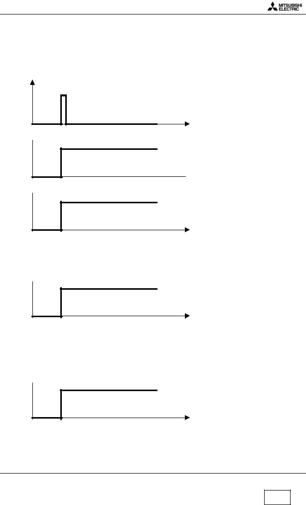
2.6Power on.
To switch on the mobile, three possibilities exist :
With a battery :
PWRKEY
t
BBPWR 
IC300 pin L8
 t
t
MUPSU 
IC100 pin49
t
During these mode TESTPS and EXPS = low voltage level.
A high voltage level on MUPSU implies regulators REG 4, REG 5, REG 6, REG 7 are active.
- With Interface and I/O connector (Testmode M.T.S) :
TESTPS
to |
t |
t0= connexion I/O cable
When you connect I/O connector, MUPSU and BBPWR signals have the same waveform at TESTPS.
During this condition PWRKEY and EXPS = low voltage level.
- With AC/DC Charger, Cigar Light Adapter and DeskTop Charger.
EXPS
t0
t0= connection by external power.
When an accessory is connect, MUPSU and BBPWR signals have the same waveform that TESTPS. During this condition PWRKEY and TESTPS = low voltage level
Mitsubishi Electric Telecom Europe SA ZA le Piquet, 35370 Etrelles
Phone: +33 2 99 75 71 00 Fax: + 33 2 99 75 71 47
Version E
Date: 04/00
9/29
 Loading...