


 Loading...
ENGLISH
DLP™ PROJECTOR
MODEL
EX321U/EX241U
User Manual
EX321U/EX241U
This User Manual is important to you.
Please read it before using your projector.
CAUTION
RISK OF ELECTRIC SHOCK
DO NOT OPEN
CAUTION: TO REDUCE THE RISK OF ELECTRIC
SHOCK,
DO NOT REMOVE COVER (OR BACK)
NO USER-SERVICEABLE PARTS INSIDE
REFER SERVICING TO QUALIFIED
SERVICE PERSONNEL.
The lightning flash with arrowhead symbol within an equilateral triangle is intended to alert the user to the presence of uninsulated "dangerous voltage" within the product’s enclosure that may be of sufficient magnitude to constitute a risk of electric shock.
The exclamation point within an equilateral triangle is intended to alert the user to the presence of important operating and maintenance (servicing) instructions in the literature accompanying the appliance.
WARNING:
TO PREVENT FIRE OR SHOCK HAZARD, DO NOT EXPOSE THIS APPLIANCE TO RAIN OR MOISTURE.
CAUTION:
TO PREVENT ELECTRIC SHOCK, DO NOT USE THIS (POLARIZED) PLUG WITH AN EXTENSION CORD, RECEPTACLE OR OTHER OUTLET UNLESS THE BLADES CAN BE FULLY INSERTED TO PREVENT BLADE EXPOSURE.
NOTE:
SINCE THIS PROJECTOR IS PLUGGABLE EQUIPMENT, THE SOCKET-OUTLET SHALL BE INSTALLED NEAR THE EQUIPMENT AND SHALL BE EASILY ACCESSIBLE.
WARNING
Use the attached specified power supply cord. If you use another power supply cord, it may cause interference with radio and television reception.
Use the attached RGB cable with this equipment so as to keep interference within the limits of an FCC Class B device.
This apparatus must be grounded.
DO NOT LOOK DIRECTLY INTO THE LENS WHEN THE PROJECTOR IS IN THE POWER ON MODE.
CAUTION
Not for use in a computer room as defined in the Standard for the Protection of Electronic Computer/Data Processing Equipment, ANSI/ NFPA 75.
The attached power cord is to be used exclusively for this product. Never use it for other products.
When using the projector in Europe: COMPLIANCE NOTICE
This Projector complies with the requirements of the EC Directive 2004/108/EC "EMC Directive" and 2006/95/EC "Low Voltage Directive".
The electro-magnetic susceptibility has been chosen at a level that gains proper operation in residential areas, on business and light industrial premises and on small-scale enterprises, inside as well as outside of the buildings. All places of operation are characterized by their connection to the public low voltage power supply system.
WARNING
Use the attached RGB cable with this equipment so as to keep interference within the limits of an EN55022 Class B device.
When using the projector in South Korea:
WARNING
Use the attached RGB cable with this equipment so as to keep interference within the limits of a K00022 Class B device.
Please follow WARNING instructions.
EN-2

Note: This symbol mark is for EU |
Your MITSUBISHI ELECTRIC product is designed and manufactured with high quality |
|
|
|
countries only. |
materials and components which can be recycled and/or reused. |
|
|
|
ENGLISH |
||||
IV, and/or to the directive 2006/66/ |
bol means that the battery or accumulator contains a heavy metal at a certain concen- |
|||
This symbol mark is according to |
This symbol means that electrical and electronic equipment, batteries and accumula- |
|
|
|
the directive 2002/96/EC Article 10 |
tors, at their end-of-life, should be disposed of separately from your household waste. |
|
|
|
Information for users and Annex |
If a chemical symbol is printed beneath the symbol shown above, this chemical sym- |
|
|
|
EC Article 20 Information for end- |
tration. This will be indicated as follows: |
|
|
|
users and Annex II. |
Hg: mercury (0,0005%), Cd: cadmium (0,002%), Pb: lead (0,004%) |
|
|
|
|
In the European Union there are separate collection systems for used electrical and |
|
|
|
|
electronic products, batteries and accumulators. |
|
|
|
|
Please, dispose of this equipment, batteries and accumulators correctly at your local |
|
|
|
|
community waste collection/recycling centre. |
|
|
|
|
Please, help us to conserve the environment we live in! |
|
|
|
|
|
|
|
|
WARNING
•If the projector comes with a lens cap, please note that the lens cap is for protecting the lens. If you leave the lens cap on the lens with the projector turned on, it may be deformed because of heat buildup. Remove the lens cap when you turn on the projector.
•One of power cords for the U.S., EU/Indonesia, U.K., Australia, South Korea and Argentina is provided appropriately.
•This projector uses the power plug of three-pin grounding type. Do not remove the grounding pin from the power plug. If the power plug doesn’t fit your wall outlet, ask an electrician to change the wall outlet.
•In case that the power cord for the U.S. is provided with this projector, never connect this cord to any outlet or power supply using other voltages or frequencies than rated. If you want to use a power supply using other voltage than rated, prepare an appropriate power cord separately.
•Use 100-240 V AC 50/60 Hz to prevent fire or electric shock.
•Do not place any objects on the power cord or do not place the projector near heat sources to prevent damage to the power cord. If the power cord should be damaged, contact your dealer for replacement because it may cause fire or electric shock.
•Do not modify or alter the power cord. If the power cord is modified or altered, it may cause fire or electric shock.
EN-3

Contents
Important safeguards ............................................................................................................................. |
5 |
Projector exterior view .......................................................................................................................... |
7 |
Controls and functions........................................................................................................................... |
8 |
Positioning your projector ................................................................................................................... |
11 |
Connection........................................................................................................................................... |
16 |
Operation ............................................................................................................................................. |
21 |
Adjusting the projected image ............................................................................................................. |
25 |
Optimizing the image .......................................................................................................................... |
28 |
3D ........................................................................................................................................................ |
34 |
Supervising and controlling by computer............................................................................................ |
36 |
Menu operation.................................................................................................................................... |
41 |
Maintenance......................................................................................................................................... |
47 |
Lamp information ................................................................................................................................ |
48 |
Indicators ............................................................................................................................................. |
53 |
Troubleshooting................................................................................................................................... |
54 |
Specifications....................................................................................................................................... |
55 |
Declaration of Conformity
Model Number: |
EX321U/EX241U |
Trade Name: |
MITSUBISHI ELECTRIC |
Responsible party: |
Mitsubishi Digital Electronics America, Inc. |
|
9351 Jeronimo Road, Irvine, CA 92618 U.S.A |
Telephone number: |
+1-(949) 465-6000 |
This device complies with Part 15 of the FCC Rules. Operation is subject to the following two conditions:
(1) this device may not cause harmful interference, and
(2) this device must accept any interference received, including interference that may cause undesired operation.
Trademark, Registered trademark
Macintosh is registered trademark of Apple Computer Inc.
DLP™, Digital Micromirror Device, DMD, and BrilliantColor™ are all trademarks of Texas Instruments.
HDMI, the HDMI logo and High-Definition Multimedia Interface are trademarks or registered trademarks of HDMI Licensing LLC.
Microsoft, Windows, Windows XP, Windows Vista, and Internet Explorer are registered trademarks, trademarks, or trade names of Microsoft Corporation in the U.S. and/or other countries.
Other brand or product names are trademarks or registered trademarks of their respective holders.
EN-4
Important safeguards
Please read all these instructions regarding your projector and retain them for future reference. Follow all warnings and instructions marked on the projector.
1.Read instructions
All the safety and operating instructions should be read before the appliance is operated.
2.Retain instructions
The safety and operating instructions should be retained for future reference.
3.Warnings
All warnings on the appliance and in the operating instructions should be adhered to.
4.Instructions
All operating instructions must be followed.
5.Cleaning
Unplug this projector from the wall outlet before cleaning it. Do not use liquid aerosol cleaners. Use a damp soft cloth for cleaning.
6.Attachments and equipment
Never add any attachments and/or equipment without the approval of the manufacturer as such additions may result in the risk of fire, electric shock or other personal injury.
7.Water and moisture
Do not use this projector near water or in contact with water.
8.Accessories
Do not place this projector on an unstable cart, stand, tripod, bracket or table. Use only with a cart, stand, tripod bracket, or table recommended by the manufacturer or sold with the projector. Any mounting of the appliance should follow the manufacturer’s instructions and should use a mounting accessory recommended by the manufacturer.
An appliance and cart combination should be moved with care. Quick stops, excessive force and uneven surfaces may cause the appliance and cart combination to overturn.
9.Ventilation
Slots and openings in the cabinet are provided for ventilation, ensuring reliable operation of the projector and to protect it from overheating. Do not block these openings or allow them to be blocked by placing the projector on a bed, sofa, rug, or bookcase. Ensure that there is adequate ventilation and that the manufacturer’s instructions have been adhered to.
10.Power sources
This projector should be operated only from the type of power source indicated on the marking label. If you are not sure of the type of power, please consult your appliance dealer or local power company.
11.Power-cord protection
Power-supply cords should be routed so that they are not likely to be walked on or pinched by items placed upon or against them. Pay particular attention to cords at plugs, convenience receptacles, and points where they exit from the appliance. Do not put the power cord under a carpet.
12.Overloading
Do not overload wall outlets and extension cords as this can result in a fire or electric shock.
13.Objects and liquids
Never push objects of any kind through openings of this projector as they may touch dangerous voltage points or short-out parts that could result in a fire or electric shock. Never spill liquid of any kind on the projector.
14.Servicing
Do not attempt to service this projector yourself. Refer all servicing to qualified service personnel.
15.Damage requiring service
Unplug this projector from the wall outlet and refer servicing to qualified service personnel under the following conditions:
(a)If the power-supply cord or plug is damaged.
(b)If liquid has been spilled, or objects have fallen into the projector.
(c)If the projector does not operate normally after you follow the operating instructions. Adjust only those controls that are covered by the operating instructions. An improper adjustment of other controls may result in damage and may often require extensive work by a qualified technician to restore the projector to its normal operation.
(d)If the projector has been exposed to rain or water.
(e)If the projector has been dropped or the cabinet has been damaged.
(f)If the projector exhibits a distinct change in performance - this indicates a need for service.
16.Replacement parts
When replacement parts are required, be sure that the service technician has used replacement parts specified by the manufacturer or parts having the same characteristics as the original part. Unauthorized substitutions may result in fire, electric shock or other hazards.
17.Safety check
Upon completion of any service or repair to this projector, ask the service technician to perform safety checks determining that the projector is in a safe operating condition.
ENGLISH
EN-5

WARNING:
Unplug immediately if there is something wrong with your projector.
Do not operate if smoke, strange noise or odor comes out of your projector. It may cause fire or electric shock. In this case, unplug immediately and contact your dealer.
Never remove the cabinet.
This projector contains high voltage circuitry. An inadvertent contact may result in an electric shock. Except as specifically explained in User Manual, do not attempt to service this product by yourself. Please contact your dealer when you want to fix, adjust, or inspect the projector.
Do not modify the projector.
It can lead to fire or electric shock.
Do not keep using the damaged projector.
If the projector is dropped and the cabinet is damaged, unplug the projector and contact your dealer for inspection. It may lead to fire if you keep using the damaged projector.
Do not face the projection lens to the sun.
It can lead to fire.
Use correct voltage.
If you use incorrect voltage, it can lead to fire.
Do not place the projector on uneven surface.
Place the projector on a level and stable surface only.
Do not look into the lens when the projector is operating.
It may hurt your eyes. Never let children look into the lens when the projector is on.
Do not unplug the power cord during operation.
It can lead to lamp breakage, fire, electric shock or other trouble. Wait for the fan to stop before unplugging the power cord.
Do not touch the air outlet grilles and bottom plate.
Do not touch them or put other equipment close to the air outlet grilles because they become hot during operation. The heated air outlet grilles and bottom plate may cause injury or damage to other equipment. Also, do not put the projector on a desk that is easily affected by heat.
Do not look into the air outlet grilles when projector is operating.
Heat, dust, etc. may blow out of them and hurt your eyes.
Do not block the air inlet and outlet grilles.
If they are blocked, heat may be generated inside the projector, causing deterioration in the projector quality and fire.
Do not use flammable solvents (benzene, thinner, etc.) and flammable aerosols near the projector.
Flammable substances may ignite causing fire or breakdown because the temperature inside the projector rises very high while the lamp is illuminating.
Do not use the projector with condensation on it.
It can lead to breakdown or other failure.
Place of installation
For safety’s sake, do not use the projector at any place subjected to high temperature and high humidity. Please maintain an operating temperature, humidity, and altitude as specified below.
•Operating temperature: between +41°F (+5°C) and +95°F (+35°C)
•Operating humidity: between 30% and 90%
•Never put any heat-producing device under the projector to prevent the projector from being overheated.
•Do not install the projector at a place that is unstable or subject to vibration.
•Do not install the projector near any equipment that produces a strong magnetic field. Also refrain from installing the projector near any cable carrying a large amount of current.
•Place the projector on a solid, vibration-free surface. Otherwise it may fall, causing serious injury or damage.
•Do not stand the projector on its end. It may fall, causing serious injury or damage.
•Slanting the projector more than ±10° (right and left) or ±15° (front and rear) may cause trouble or explosion of the lamp.
•Do not place the projector near air-conditioning unit, heater, or humidifier to avoid hot or moist air to the exhaust and ventilation hole of the projector.
•Be sure to use this projector at an altitude of less than 1500 meters.
COMPLIANCE NOTICE OF FCC
This equipment has been tested and found to comply with the limits for a Class B digital device, pursuant to Part 15 of the FCC Rules. These limits are designed to provide reasonable protection against harmful interference in a residential installation. This equipment generates, uses and can radiate radio frequency energy and, if not installed and used in accordance with the instructions, may cause harmful interference to radio communications. However, there is no guarantee that interference will not occur in a particular installation. If this equipment does cause harmful interference to radio or television reception, which can be determined by turning the equipment off and on, the user is encouraged to try to correct the interference by one or more of the following measures:
•Reorient or relocate the receiving antenna.
•Increase the separation between the equipment and receiver.
•Connect the equipment into an outlet on a circuit different from that to which the receiver is connected.
•Consult the dealer or an experienced Radio / TV technician for help.
Any changes or modifications not expressly approved by Mitsubishi could void the user’s authority to operate this equipment.
COMPLIANCE NOTICE OF INDUSTRY CANADA
This Class B digital apparatus complies with Canadian ICES-003.
EN-6
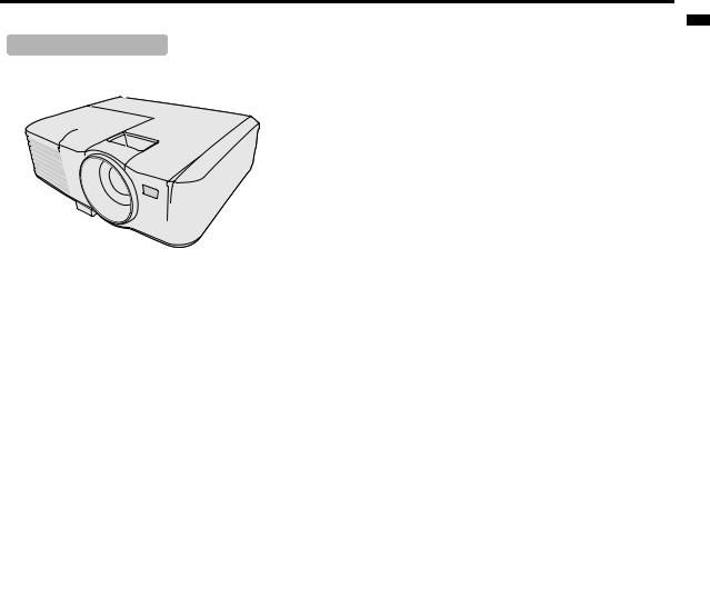
Projector exterior view
Front/upper side |
|
1. |
External control panel |
|
|
|
(See "Projector" on page 8 for details.) |
||
1 |
5 |
2. |
Lamp cover |
|
3. |
Vent (heated air exhaust) |
|||
|
||||
2 |
|
4. |
Quick-release button |
|
|
5. |
Focus ring and Zoom ring |
||
|
|
|||
|
|
6. |
Front IR remote sensor |
|
|
|
7. |
Projection lens |
|
|
|
8. |
Vent (air intake) |
8 |
Do not replace the lamp immediately after using the projector |
|
because the lamp would be extremely hot and it may cause |
3 |
burns. |
4
6
7
Rear/lower side |
|
|
|
|
|
|
|
9. |
RGB signal output socket |
|
|
|
|
|
|
|
10. |
RGB (PC)/Component Video (YPbPr/ YCbCr) signal |
|
|
|
|
|
|
|
|
|
||
9 |
10 |
11 |
12 |
13 |
14 |
15 |
|
|
input socket x 2 |
|
11. |
HDMI input port |
|||||||
|
|
|
|
|
|
|
|
||
|
|
|
|
|
|
|
|
12. |
Serial control port |
|
|
|
|
|
|
|
|
13. |
LAN (RJ-45) port |
|
|
|
|
|
|
|
|
14. |
Audio input jack |
|
|
|
|
|
|
|
|
|
Audio output jack |
|
|
|
|
|
|
|
|
15. |
S-Video input socket |
|
|
|
|
|
|
|
|
|
Video input socket |
|
|
|
|
|
|
|
|
16. |
Kensington lock |
|
|
|
|
|
|
|
|
17. |
AC power cord inlet |
|
|
|
|
|
|
|
19 |
18. |
Quick-release foot |
16 |
|
|
|
|
|
|
|
||
|
|
|
|
|
|
|
19. |
Security bar |
|
|
|
|
|
|
|
|
|
||
17 |
|
|
|
|
|
|
|
20. |
Rear adjuster foot |
|
|
|
|
|
|
|
Kensington Lock |
||
|
|
|
|
|
|
|
|
||
18 |
|
This projector has a Kensington Security Standard connector |
|
|
|
|
20 |
for use with Kensington MicroSaver Security System. |
|
|
|
|
|
Refer to the information that came with the Kensington System |
|
|
for instructions on how to use it to secure the projector. Please |
|
|
contact Kensington Technology Group below. |
|
|
Kensington Technology Group |
|
|
2855 Campus Drive |
|
|
San Mateo, CA 94403, U.S.A. |
|
|
Phone: +1- (650)572-2700 Fax: +1- (650)572-9675 |
ENGLISH
EN-7
Controls and functions
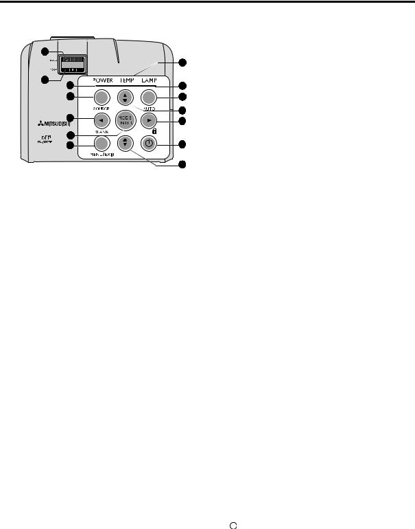
Projector
1
2
3
4
5
6 
7
8
9
10
11
12
13
11
1.Focus ring
Adjusts the focus of the projected image. See "Finetuning the image size and clarity" on page 25 for details.
2.Zoom ring
Adjusts the size of the image. See "Fine-tuning the image size and clarity" on page 25 for details.
3.POWER indicator light
Lights up or flashes when the projector is under operation. See "Indicators" on page 53 for details.
4.SOURCE
Displays the source selection bar. See "Switching input signal" on page 24 for details.
5. Left/BLANK
Used to hide the screen picture. See "Hiding the image" on page 32 for details.
6.MODE/ENTER
Selects an available picture setup mode. See "Selecting a picture mode" on page 28 for details.
Enacts the selected On-Screen Display (OSD) menu item.
7.MENU/EXIT
Turns on the On-Screen Display (OSD) menu. Goes back to previous OSD menu, exits and saves menu settings. See "Using the menus" on page 22 for details.
8.TEMPerature indicator light
Lights up red if the projector's temperature becomes too high. See "Indicators" on page 53 for details.
9.LAMP indicator light
Indicates the status of the lamp. Lights up or flashes when the lamp has developed a problem. See "Indicators" on page 53 for details.
10.AUTO
Automatically determines the best picture timings for the displayed image. See "Auto-adjusting the image" on page 25 for details.
11.Keystone/Arrow keys (  /
/ Up,
Up,  /
/ Down)
Down)
Manually corrects distorted images resulting from an angled projection. See "Correcting keystone" on page 26 for details.
12. Right/
Activates panel key lock. See "Locking control keys" on page 32 for details.
When the On-Screen Display (OSD) menu is activated, the #5, #11, and #12 keys are used as directional arrows to select the desired menu items and to make adjustments. See "Using the menus" on page 22 for details.
13.II POWER (ON/STANDBY)
Toggles the projector between standby mode and on. See "Starting up the projector" on page 21 and "Shutting down the projector" on page 33 for details.
EN-8
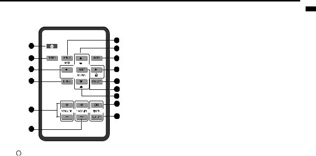
Remote control |
|
|
1 |
7 |
|
8 |
||
|
||
2 |
9 |
|
3 |
10 |
|
4 |
11 |
|
|
12 |
|
|
8 |
|
|
13 |
|
5 |
|
|
|
14 |
|
6 |
|
1. II POWER (ON/STANDBY)
Toggles the projector between standby mode and on. See "Starting up the projector" on page 21 and "Shutting down the projector" on page 33 for details.
2.FREEZE
Freezes the projected image. See "Freezing the image" on page 32 for details.
3. Left
Left
Selects the desired menu items and makes adjustments. See "Using the menus" on page 22 for details.
4.BLANK
Used to hide the screen picture. See "Hiding the image" on page 32 for details.
5.VOLUME keys (+, -)
Adjusts the sound level. See "Adjusting the sound" on page 32 for details.
6.MAGNIFY keys (+, -)
Magnifies or reduces the projected picture size. See "Magnifying and searching for details" on page 26 for details.
7.MENU/EXIT
Turns on the On-Screen Display (OSD) menu. Goes back to previous OSD menu, exits and saves menu settings. See "Using the menus" on page 22 for details.
8.Keystone/Arrow keys ( /
/ Up,
Up,  /
/ Down)
Down)
Manually corrects distorted images resulting from an angled projection. See "Correcting keystone" on page 26 for details.
9.AUTO
Automatically determines the best picture timings for the displayed image. See "Auto-adjusting the image" on page 25 for details.
10. Right/
Activates panel key lock. See "Locking control keys" on page 32 for details.
When the On-Screen Display (OSD) menu is activated, the #3, #8 and #10 keys are used as directional arrows to select the desired menu items and to make adjustments. See "Using the menus" on page 22 for details.
11.SOURCE
Displays the source selection bar. See "Switching input signal" on page 24 for details.
12.MODE/ENTER
Depending upon which input signal is selected, selects an available picture setup mode. See "Selecting a picture mode" on page 28 for details.
Enacts the selected On-Screen Display (OSD) menu item.
13.TIMER ON
Activates or displays an on-screen timer based on your own timer setting. See "Setting the presentation timer" on page 31 for details.
14.TIMER SET UP
Enters presentation timer setting directly. See "Setting the presentation timer" on page 31 for details.
EN-9
ENGLISH
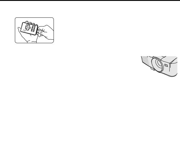
Using the remote control for the first time
Pull the tab before using the remote control.
Remote control effective range
Infra-Red (IR) remote control sensor is located on the front of the projector. The remote control must be held at an angle within 30 degrees perpendicular to the projector's IR remote control sensor to function correctly. The distance between the remote control and the sensor should not exceed 8 meters (~ 26 feet).
Make sure that there are no obstacles between the remote control and the IR sensor on the projector that might obstruct the infra-red beam.
•Do not let the IR transmitter of the remote control be shined by sunlight or fluorescent lamps directly.
 Approx. 15°
•Please keep the remote controller away from fluorescent lamps for over 2 m or the remote controller might become malfunction.
•If the remote control is close to Inverter-Type fluorescent lamps, it might become ineffective from time to time.
•If the remote control and the projector are within a very short distance, the remote control might become ineffective.
•When you aim at the screen, the effective distance is less than 5 m from the remote control to the screen and reflecting the IR beams back to the projector. However, the effective range might change according to screens.
Replacing the remote control battery
1.Pull out the battery holder.
Please follow the illustrated instructions. Push and hold the locking arm while pulling out the battery holder.
2. Insert the new battery in the holder. Note the positive polarity should face outward.
3. Push the holder into the remote control.
 • Risk of explosion if battery is replaced by an incorrect type.
• Dispose of used batteries according to the instructions.
•Use of a battery of wrong type may cause explosion. Use Lithium coin battery, type CR2025 only.
•Dispose of used batteries according to your local regulations. Discard used battery promptly. Batteries may explode if mistreated. Do not recharge, disassemble, or dispose of in fire.
•Be careful in handling the battery according to the instructions.
•Load the battery with its positive (+) and negative (-) sides correctly oriented as indicated on the remote control.
•Keep batteries out of reach of children and pets.
•Remove the battery if the remote control is not used for a long time.
•Keep battery in original package until ready to use.
•Never put battery in mouth for any reason as it can easily be accidentally swallowed. If battery is accidentally swallowed, contact your physician or your poison control center.
•Dispose of the used battery with cellophane tape wrapping both ends of it.
EN-10

Positioning your projector
Choosing a location
Your room layout or personal preference will dictate which installation location you select. Take into consideration the size and position of your screen, the location of a suitable power outlet, as well as the location and distance between the projector and the rest of your equipment.
Your projector is designed to be installed in one of the possible installation locations:
1.Front Table
Select this location with the projector placed near the floor in front of the screen. This is the most common way to position the projector for quick setup and portability.
2.Rear Table
Select this location with the projector placed near the floor behind the screen.
Note that a special rear projection screen is required.
Set Rear Table in the SYSTEM SETUP: Basic >
Projector Position menu after you turn the projector on.
3.Rear Ceiling
Select this location with the projector suspended upsidedown from the ceiling behind the screen.
Note that a special rear projection screen and qualified projector ceiling mount kit are required for this installation location.
Set Rear Ceiling in the SYSTEM SETUP: Basic >
Projector Position menu after you turn the projector on.
4.Front Ceiling
Select this location with the projector suspended upsidedown from the ceiling in front of the screen.
Purchase a qualified projector ceiling mount kit from your dealer to mount your projector on the ceiling.
Set Front Ceiling in the SYSTEM SETUP: Basic >
Projector Position menu after you turn the projector on.
For ceiling mounting, you need the ceiling mount kit designed for this projector. Ask a specialist for installation.For details, consult your dealer.
•The warranty on this projector does not cover any damage caused by use of any non-recommended ceiling mount kit or installation of the ceiling mount kit in an improper location.
•When the projector is mounted on the ceiling, images may appear darker than those projected in the case of tabletop mounting. This isn’t a product malfunction.
• Be sure to use this projector at an altitude of less than 1500 meters.
•Installation must be done by a qualified professional.
When the projector is installed on the ceiling using the ceiling mount kit, it is recommended to hold the mount kit and the projector using metal bars or wires in addition to the mount kit fixing screws to prevent the projector from falling due to an earthquake or other cause. For that purpose, use metal bars, wires, or screws that bear a load of at least 70 kgf. When using metal wires, secure one end to a screw hole marked with an arrow on the rear terminal panel and the other end to the mount kit. (Do not use screw holes without arrow marks.) In this case, make sure that the screws are inserted in the projector at least 5 mm. The length of the screws should be 20 mm or shorter. Also make sure that no electrical current is flowing in the mount kit due to current leakage or other cause.
ENGLISH
EN-11
Obtaining a preferred projected image size
The distance from the projector lens to the screen, the zoom setting (if available), and the video format each factors in the projected image size.
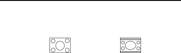
4:3 is the native aspect ratio of EX321U/EX241U. To be able to project a complete 16:9 (widescreen) aspect ratio image, the projector can resize and scale a widescreen image to the projector's native aspect width. This will result in a proportionally smaller height equivalent to 75% of the projector's native aspect height.
4:3 aspect image in a 4:3 aspect display area 16:9 aspect image scaled to a 4:3 aspect display area
Thus, a 16:9 aspect image will not utilize 25% of the height of a 4:3 aspect image displayed by this projector. This will be seen as darkened (unlit) bars along the top and bottom (vertical 12.5% height respectively) of the 4:3 projection display area whenever displaying a scaled 16:9 aspect image in the vertical center of the 4:3 projection display area.
The projector should always be placed horizontally level (like flat on a table), and positioned directly perpendicular (90° right-angle square) to the horizontal center of the screen. This prevents image distortion caused by angled projections (or projecting onto angled surfaces).
The modern digital projector does not project directly forward (like older style reel-to-reel film projectors did). Instead, digital projectors are designed to project at a slightly upward angle above the horizontal plane of the projector. This is so that they can be readily placed on a table and will project forward and upwards onto a screen positioned so that the bottom edge of the screen is above the level of the table (and everyone in the room can see the screen).
You can see from the diagram on page 14, that this type of projection causes the bottom edge of the projected image to be vertically offset from the horizontal plane of the projector.
If the projector is positioned further away from the screen, the projected image size increases, and the vertical offset also increases proportionately.
When determining the position of the screen and projector, you will need to account for both the projected image size and the vertical offset dimension, which are directly proportional to the projection distance.
When fine streaks are seen on projected images
This is due to interference with the screen surface and is not a mal-function. Replace the screen or displace the focus a little.
EN-12

How to determine the position of the projector for a given screen size
1.Determine the aspect ratio of your screen, 16:9 or 4:3. If you have a 4:3 screen, refer to the table labeled "(Standard)". If you have a 16:9 screen, refer to the table labeled "(16:9)".
2.Select your image size.
3.Refer to the table and find the closest match to your image size in the left columns labeled "Image size". Using this value, look across this row to the right to find the corresponding average distance from screen value in the column labeled "Distance from the screen: L". This is the projection distance.
4.On that same row, look across to the right column and make note of the "Hd" value. This will determine the final vertical offset placement of the projector in relation to the edge of the image.
5.The recommended position for the projector is aligned perpendicular to the horizontal center of the screen, at the distance from the screen determined in step 3 above, and offset by the value determined in step 4 above.
<Example>
EX321U: If you are using a 4:3 aspect ratio, 100-inch screen, distance from the screen is 3.1 m and with a vertical offset of 11 cm at Zoom position wide.
If you place the projector in a different position (to that recommended), you will have to tilt it down or up to center the image on the screen. In these situations, some image distortion will occur. Use the Keystone function to correct the distortion. See "Correcting keystone" on page 26 for details.
How to determine the recommended screen size for a given distance
This method can be used for situations where you have purchased this projector and would like to know what screen size will fit in your room.
The maximum screen size is limited by the physical space available in your room.
1.Measure the distance between the projector and where you want to position the screen. This is the projection distance.
2.Refer to the table "(Standard)" or "(16:9)", and find the closest match to your measurement in the distance from the Image size column. If the min and max values are available on the table, check that your measured distance is between the min and max distances listed on either side of the average distance value.
3.Using this value, look across that row to the left to find the corresponding "Image size". That is the projected image size of the projector at that projection distance.
4.On that same row, look across to the right column and make note of the "Hd" value. This will determine the final placement of the screen in relation to the horizontal plane of the projector.
<Example>
EX321U: If your measured projection distance was 3.5 m and your screen aspect ratio is 4:3, the closest match in the "Distance from the screen: L" column is from 3.1 m to 4.0 m. Looking across this row shows that a 100-inch screen is required.
ENGLISH
EN-13
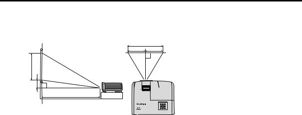
Layout of the projector
Image size varies depending on the distance between the screen and the projector.
Front projection
|
W |
A |
B |
H |
|
Hd |
A=B |
|
|
L |
|
L: Between the screen and the front edge of the projector
H: Height of the projected image
(Standard)
EX321U (4:3)
|
|
Image size |
|
|
Distance from the screen: L |
|
Hd |
|||||
Diagonal Size |
Width: W |
Height: H |
Shortest (Wide) |
Longest (Tele) |
|
|||||||
|
|
|
||||||||||
inch |
cm |
inch |
cm |
inch |
cm |
inch |
m |
inch |
m |
inch |
|
cm |
40 |
102 |
32 |
81 |
24 |
61 |
48 |
1.2 |
63 |
1.6 |
2 |
|
5 |
60 |
152 |
48 |
122 |
36 |
91 |
73 |
1.8 |
94 |
2.4 |
3 |
|
7 |
80 |
203 |
64 |
163 |
48 |
122 |
97 |
2.5 |
126 |
3.2 |
4 |
|
9 |
100 |
254 |
80 |
203 |
60 |
152 |
121 |
3.1 |
157 |
4.0 |
5 |
|
11 |
120 |
305 |
96 |
244 |
72 |
183 |
145 |
3.7 |
189 |
4.8 |
5 |
|
14 |
150 |
381 |
120 |
305 |
90 |
229 |
182 |
4.6 |
236 |
6.0 |
7 |
|
17 |
200 |
508 |
160 |
406 |
120 |
305 |
242 |
6.2 |
315 |
8.0 |
9 |
|
23 |
250 |
635 |
200 |
508 |
150 |
381 |
303 |
7.7 |
394 |
10.0 |
11 |
|
29 |
300 |
762 |
240 |
610 |
180 |
457 |
363 |
9.2 |
472 |
12.0 |
14 |
|
34 |
EX241U (4:3)
|
|
Image size |
|
|
Distance from the screen: L |
|
Hd |
|||||||||
Diagonal Size |
Width: W |
Height: H |
Shortest (Wide) |
Longest (Tele) |
|
|||||||||||
|
|
|
||||||||||||||
inch |
cm |
inch |
cm |
inch |
cm |
inch |
m |
inch |
|
m |
inch |
|
cm |
|||
40 |
102 |
32 |
81 |
24 |
61 |
60 |
1.5 |
66 |
|
1.7 |
|
2 |
|
6 |
||
60 |
152 |
48 |
122 |
36 |
91 |
90 |
2.3 |
99 |
|
2.5 |
|
4 |
|
9 |
||
80 |
203 |
64 |
163 |
48 |
122 |
120 |
3.0 |
132 |
3.4 |
|
5 |
|
12 |
|||
100 |
254 |
80 |
203 |
60 |
152 |
150 |
3.8 |
165 |
4.2 |
|
6 |
|
15 |
|||
150 |
381 |
120 |
305 |
90 |
229 |
225 |
5.7 |
247 |
6.3 |
|
9 |
|
23 |
|||
200 |
508 |
160 |
406 |
120 |
305 |
300 |
7.6 |
330 |
8.4 |
|
12 |
|
30 |
|||
250 |
635 |
200 |
508 |
150 |
381 |
375 |
9.5 |
412 |
10.5 |
15 |
|
38 |
||||
300 |
762 |
240 |
610 |
180 |
457 |
450 |
11.4 |
|
|
|
|
|
|
18 |
|
46 |
|
|
|
|
|
|
|||||||||||
EN-14

(16:9)
EX321U
|
|
Image size |
|
|
Distance from the screen: L |
|
Hd |
|||||||||
Diagonal Size |
Width: W |
Height: H |
Shortest (Wide) |
Longest (Tele |
|
|||||||||||
|
|
|
||||||||||||||
inch |
cm |
inch |
cm |
inch |
cm |
inch |
m |
inch |
|
m |
inch |
|
cm |
|||
40 |
102 |
35 |
89 |
20 |
50 |
52 |
1.3 |
68 |
|
1.7 |
|
5 |
|
13 |
||
|
|
|
|
|
|
|
|
|
|
|
|
|
|
|||
60 |
152 |
52 |
133 |
29 |
75 |
78 |
2.0 |
102 |
2.6 |
|
8 |
|
20 |
|||
|
|
|
|
|
|
|
|
|
|
|
|
|
|
|||
80 |
203 |
70 |
177 |
39 |
100 |
105 |
2.7 |
136 |
3.5 |
|
10 |
|
26 |
|||
|
|
|
|
|
|
|
|
|
|
|
|
|
|
|||
100 |
254 |
87 |
221 |
49 |
125 |
131 |
3.3 |
170 |
4.3 |
|
13 |
|
33 |
|||
|
|
|
|
|
|
|
|
|
|
|
|
|
|
|||
120 |
305 |
105 |
266 |
59 |
149 |
157 |
4.0 |
204 |
5.2 |
|
16 |
|
40 |
|||
|
|
|
|
|
|
|
|
|
|
|
|
|
|
|||
150 |
381 |
131 |
332 |
74 |
187 |
196 |
5.0 |
255 |
6.5 |
|
19 |
|
49 |
|||
|
|
|
|
|
|
|
|
|
|
|
|
|
|
|||
200 |
508 |
174 |
443 |
98 |
249 |
261 |
6.6 |
340 |
8.6 |
|
26 |
|
66 |
|||
|
|
|
|
|
|
|
|
|
|
|
|
|
||||
250 |
635 |
218 |
553 |
123 |
311 |
327 |
8.3 |
425 |
10.8 |
32 |
|
82 |
||||
|
|
|
|
|
|
|
|
|
|
|
|
|
|
|
|
|
300 |
762 |
261 |
664 |
147 |
374 |
392 |
10.0 |
|
|
|
|
|
|
39 |
|
99 |
|
|
|
|
|
|
|||||||||||
|
|
|
|
|
|
|
|
|
|
|
|
|
|
|
|
|
EX241U
|
|
Image size |
|
|
Distance from the screen: L |
|
Hd |
|||||||||
Diagonal Size |
Width: W |
Height: H |
Shortest (Wide) |
Longest (Tele |
|
|||||||||||
|
|
|
||||||||||||||
inch |
cm |
inch |
cm |
inch |
cm |
inch |
m |
inch |
|
m |
inch |
|
cm |
|||
40 |
102 |
35 |
89 |
20 |
50 |
66 |
1.7 |
73 |
|
1.9 |
|
6 |
|
15 |
||
|
|
|
|
|
|
|
|
|
|
|
|
|
|
|||
60 |
152 |
52 |
133 |
29 |
75 |
99 |
2.5 |
109 |
2.8 |
|
9 |
|
22 |
|||
|
|
|
|
|
|
|
|
|
|
|
|
|
|
|||
80 |
203 |
70 |
177 |
39 |
100 |
132 |
3.4 |
146 |
3.7 |
|
12 |
|
30 |
|||
|
|
|
|
|
|
|
|
|
|
|
|
|
|
|||
100 |
254 |
87 |
221 |
49 |
125 |
166 |
4.2 |
182 |
4.6 |
|
15 |
|
37 |
|||
|
|
|
|
|
|
|
|
|
|
|
|
|
|
|||
150 |
381 |
131 |
332 |
74 |
187 |
248 |
6.3 |
273 |
6.9 |
|
22 |
|
56 |
|||
|
|
|
|
|
|
|
|
|
|
|
|
|
|
|||
200 |
508 |
174 |
443 |
98 |
249 |
331 |
8.4 |
364 |
9.3 |
|
29 |
|
75 |
|||
|
|
|
|
|
|
|
|
|
|
|
|
|
||||
250 |
635 |
218 |
553 |
123 |
311 |
414 |
10.5 |
455 |
11.6 |
37 |
|
93 |
||||
|
|
|
|
|
|
|
|
|
|
|
|
|
|
|
|
|
275 |
699 |
240 |
609 |
135 |
342 |
455 |
11.6 |
|
|
|
|
|
|
40 |
|
103 |
|
|
|
|
|
|
|||||||||||
|
|
|
|
|
|
|
|
|
|
|
|
|
|
|
|
|
The above figures are approximate and may be slightly different from the actual measurements. Mitsubishi recommends that if you intend to permanently install the projector, you should physically test the projection size and distance using the actual projector in suit before you permanently install it, so as to make allowance for this projector's optical characteristics. This will help you determine the exact mounting position so that it best suits your installation location.
EN-15
ENGLISH
Connection
When connecting a signal source to the projector, be sure to:
1.Turn all equipment off before making any connections.
2.Use the correct signal cables for each source.
3.Ensure the cables are firmly inserted.
 • See the owner’s guide of each device for details about its connections.
•Contact your dealer for details about its connections.
•In the connections shown below, some cables may not be included with the projector. They are commercially available from electronics stores.
Connecting a computer or monitor
Connecting a computer
The projector provides a RGB input socket that allows you to connect it to both IBM® compatibles and Macintosh® computers. A Mac adapter is needed if you are connecting legacy version Macintosh computers.
To connect the projector to a notebook or desktop computer:
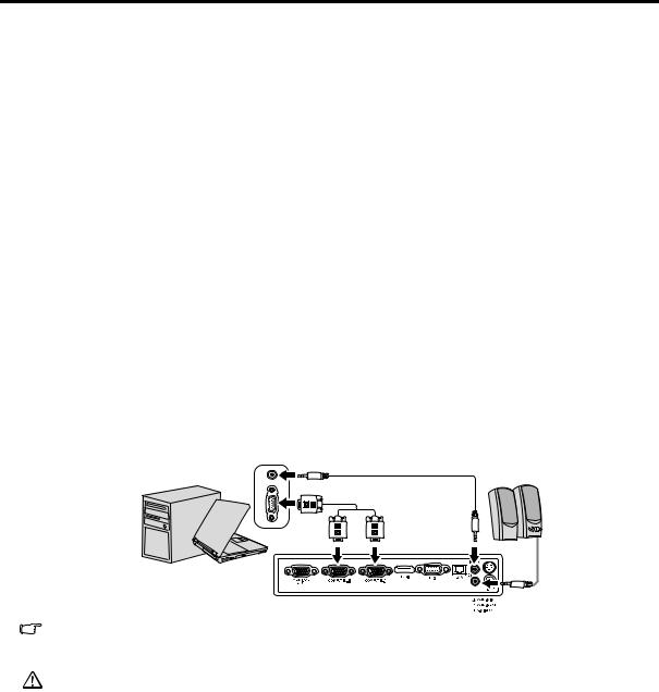
1.Take the supplied RGB cable and connect one end to the D-Sub output socket of the computer.
2.Connect the other end of the RGB cable to the COMPUTER-1 or COMPUTER-2 signal input socket of the projector.
3.If you wish to make use of the projector speaker in your presentations, take a suitable audio cable and connect one end of the cable to the audio output jack of the computer, and the other end to the AUDIO IN jack of the projector.
4.If you wish, you can use another suitable audio cable and connect one end of the cable to the AUDIO OUT jack of the projector, and the other end to your external speakers (not supplied).
Once connected, the audio can be controlled by the projector On-Screen Display (OSD) menus. See "Adjusting the sound" on page 32 for details.
The final connection path should be like that shown in the following diagram:
Notebook or desktop computer |
Audio cable (option) |
Speakers |
|
||
|
RGB cable |
|
|
or |
|
Audio cable (option)
Many notebooks do not turn on their external video ports when connected to a projector. Usually a key combo like FN + F3 or CRT/LCD key turns the external display on/off. Locate a function key labeled CRT/LCD or a function key with a monitor symbol on the notebook. Press FN and the labeled function key simultaneously. Refer to your notebook's documentation to find your notebook's key combination.
•When you use a longer RGB cable instead of the provided cable, the image may not be projected correctly.
•Some computers require additional connectors or analog RGB output adapters to be connected with this projector.
EN-16
Connecting a monitor
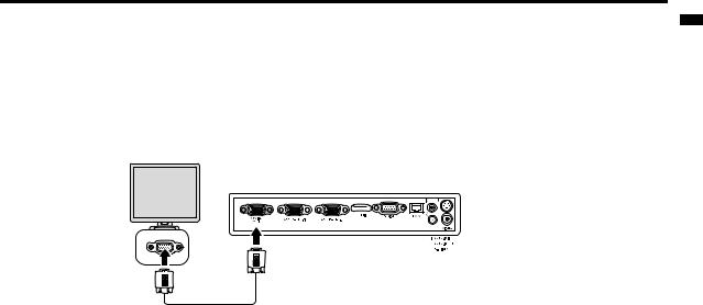
If you want to view your presentation close-up on a monitor as well as on the screen, you can connect the MONITOR OUT signal output jack on the projector to an external monitor following the instructions below:
To connect the projector to a monitor:
1.Connect the projector to a computer as described in "Connecting a computer" on page 16.
2.Connect the RGB cable from the monitor to the MONITOR OUT jack of the projector.
Notebook or desktop computer
ENGLISH
RGB cable
 • Once the Standby Monitor Out function is on, the projector can output a VGA signal when it is in standby mode and an appropriate D-Sub input is made to the COMPUTER-1 jack.
•Images may not be displayed correctly depending on the type of the input signal. See the instruction manual of the monitor.
•Images may not be displayed correctly depending on the type of the cable.
Connecting Video source devices
You can connect your projector to various Video source devices that provide any one of the following output sockets:
•HDMI
•Component Video
•S-Video
•Video (composite)
You need only connect the projector to a Video source device using just one of the above connecting methods, however each provides a different level of video quality. The method you choose will most likely depend upon the availability of matching terminals on both the projector and the Video source device as described below:
HDMI (High-Definition Multimedia Interface) supports uncompressed video data transmission between compatible devices like DTV tuners, DVD players and displays over a single cable. It provides pure digital viewing experience. See "Connecting an HDMI device" on page 18" for how to connect the projector to an HDMI device.
Digital TV tuner and DVD players output Component Video natively, so if available on your devices, this should be your connection method of choice in preference to (composite) Video. See "Connecting a Component Video source device" on page 18 for how to connect the projector to a component video device.
If you have both composite Video and S-Video output terminals on your Video source device, you should elect to use the S-Video option. See "Connecting an S-Video source device" on page 19 for how to connect the projector to an S- Video device.
If you have only composite Video output terminals on your Video source device, connect to Composite Video input. See "Connecting a composite Video source device" on page 20 for how to connect the projector to a composite Video device.
EN-17
Connecting an HDMI device
You should use an HDMI cable when making connection between the projector and HDMI devices.
To connect the projector to an HDMI device:
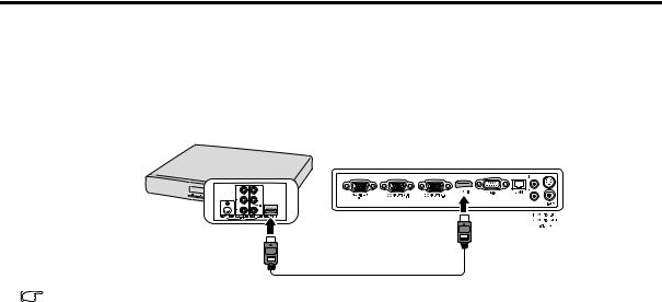
1.Take an HDMI cable and connect one end to the HDMI output port of the video device.
2.Connect the other end of the cable to the HDMI input port on the projector.
AV device
HDMI cable (option)
In the unlikely event that you connect the projector to a DVD player via the projector's HDMI input and the projected picture displays wrong colors, please change the color space to YUV. See "Changing Color Space" on page 24 for details.
When you connect this projector and a Digital device (such as a DVD player) via the HDMI terminal, black color may appear dark and deep, depending on the type of the connected device.
•This depends on the black level setting of the connected device. There are two kinds of methods to digitally transfer image data, in which different black level settings are employed respectively. Therefore, the specifications of the signals output from DVD players differ, depending on the type of the digital data transfer method they use.
•Some DVD players are provided with a function to switch the methods to output digital signals. When your DVD player is provided with such function, set it as follows.
EXPAND or ENHANCED -> NORMAL
•See the users guide of your DVD player for details.
•When you switch to HDMI input, the projected picture may display wrong colors for about 1 second. This is not product malfunction.
Connecting a Component Video source device
Examine your Video source device to determine if it has a set of unused Component Video output sockets available:
•If so, you can continue with this procedure.
•If not, you will need to reassess which method you can use to connect to the device.
To connect the projector to a Component Video source device:
1.Take a Component Video to RGB (D-Sub) adaptor cable and connect the end with 3 RCA type connectors to the Component Video output sockets of the Video source device. Match the color of the plugs to the color of the sockets; green to green, blue to blue, and red to red.
2.Connect the other end of the Component Video to RGB (D-Sub) adaptor cable (with a D-Sub type connector) to the COMPUTER-1 or COMPUTER-2 socket on the projector.
3.If you wish to make use of the projector speaker in your presentations, take a suitable audio cable and connect one end of the cable to the audio output jack of the computer, and the other end to the AUDIO IN jack of the projector.
4.If you wish, you can use another suitable audio cable and connect one end of the cable to the AUDIO OUT jack of the projector, and the other end to your external speakers (not supplied).
Once connected, the audio can be controlled by the projector On-Screen Display (OSD) menus. See "Adjusting the sound" on page 32 for details.
EN-18
Loading...