


0-1
GROUP 0
GENERAL
CONTENTS
VEHICLE IDENTIFICATION . . . . . . . |
0-2 MAJOR SPECIFICATIONS . . . . . . . . |
0-2 |
0-2 |
GENERAL |
|
VEHICLE IDENTIFICATION |
VEHICLE IDENTIFICATION
MODELS |
|
|
|
M4000001000264 |
||
|
|
|
|
|
||
|
|
|
|
|
|
|
Model code |
Engine model |
Price |
Transmission model |
Fuel supply |
|
|
|
|
|
class |
|
system |
|
NA4W |
LNUYL6/R6 |
4G69-SOHC-MIVEC |
GLX |
F5M42 <2WD, 5M/T> |
MPI |
|
|
|
(2,378 mL) |
|
|
|
|
|
LRUYL6/R6 |
|
F4A4B <2WD, 4A/T with sport mode> |
|
|
|
|
|
|
|
|
||
|
|
|
|
|
|
|
|
LNHYL6/R6 |
|
|
F5M42 <2WD, 5M/T> |
|
|
|
|
|
|
|
|
|
|
LRHYL6/R6 |
|
|
F4A4B <2WD, 4A/T with sport mode> |
|
|
|
|
|
|
|
|
|
MAJOR SPECIFICATIONS
|
|
|
|
|
|
|
|
M4000003000174 |
|
|
|
|
|
|
|
|
|
|
|
Item |
|
|
|
|
NA4W |
|
|
|
|
|
|
|
|
|
LNUYL6/ |
LNHYL6/ |
LRUYL6/ |
LRHYL6/ |
|
|
|
|
|
|
R6 |
R6 |
R6 |
R6 |
|
Vehicle |
|
Overall length |
|
|
4,765 |
|
|
|
|
dimension mm |
|
|
|
|
|
|
|
|
|
Overall width |
|
|
1,795 |
|
|
|
|
||
|
|
|
|
|
|
|
|
||
|
|
Overall height |
Without roof rails |
1,655/1,665*1 |
|
|
|
||
|
|
|
With roof rails |
|
1,690/1,700*1 |
|
|
|
|
|
|
Wheelbase |
|
|
2,830 |
|
|
|
|
|
|
|
|
|
|
|
|
|
|
|
|
Track |
Front |
|
1,550 |
|
|
|
|
|
|
|
|
|
|
|
|
|
|
|
|
|
Rear |
|
1,555 |
|
|
|
|
|
|
|
|
|
|
|
|
|
|
|
|
Front overhang |
|
|
900 |
|
|
|
|
|
|
|
|
|
|
|
|
|
|
|
|
Rear overhang |
|
|
1,035 |
|
|
|
|
|
|
|
|
|
|
|
|
|
|
|
|
Ground clearance |
|
|
155 |
|
|
|
|
Vehicle |
Front |
Toe-in (at the centre of tyre tread) |
mm |
0 ± 3 |
|
|
|
|
|
wheel |
|
|
|
|
|
|
|
|
|
|
Toe angle (per wheel) |
|
0°00' ± 08' |
|
|
|
|
||
alignment |
|
|
|
|
|
|
|||
|
Camber*3 |
|
|
0°00' ± 30' |
|
|
|
|
|
|
|
|
|
|
|
|
|
||
|
|
Caster*3 |
|
|
2°46' ± 1°00', 2°54' ± 1°00'*1 |
|
|
||
|
|
Kingpin inclination angle |
|
13°12' ± 1°30', 12°54' ± 1°30'*1 |
|
|
|||
|
Rear |
Toe-in (at the centre of tyre tread) |
mm |
3 ± 2 |
|
|
|
|
|
|
|
|
|
|
|
|
|
|
|
|
|
Toe angle (per wheel) |
|
0°08' ± 05' |
|
|
|
|
|
|
|
|
|
|
|
|
|
||
|
|
Camber*3 |
|
|
-0°45' +45'/-15', -0°05' ± 30'*1 |
|
|
||
Wheels and |
tyres |
Tyre size |
|
|
215/60 R16 95H, 215/55 R17 94V*2 |
|
|
||
|
|
Wheel size |
|
|
16 × 6 1/2JJ, 17 × 7JJ*2 |
|
|
|
|
|
|
Offset mm |
|
|
46 |
|
|
|
|
|
|
|
|
|
|
|
|
|
|
GENERAL |
0-3 |
MAJOR SPECIFICATIONS |
|
NOTE:
*1: Vehicles with high ground suspensions <LH drive vehicles>. *2: Vehicles with aluminium wheels.
*3: Difference between right and left wheels must be less than 30'.

1-1
GROUP 1
BODY
CONSTRUCTION
CONTENTS
BODY COMPONENTS. . . . . . . . . . . . |
1-2 |
BODY MAIN CROSS-SECTIONAL VIEWS |
1-4 |
. . . . . . . . . . . . . . . . . . . . . . . . . . . . . . . . . |
|
MAINTENANCE, SERVICEABILITY . |
1-6 |
BODY CONSTRUCTION CHARACTERISTICS |
|
. . . . . . . . . . . . . . . . . . . . . . . . . . . . . . . . . |
1-7 |
FRONT BODY. . . . . . . . . . . . . . . . . . . . . . . |
1-7 |
SIDE BODY. . . . . . . . . . . . . . . . . . . . . . . . . |
1-12 |
REAR BODY. . . . . . . . . . . . . . . . . . . . . . . . |
1-14 |
ROOF . . . . . . . . . . . . . . . . . . . . . . . . . . . . . |
1-15 |
UNDER BODY. . . . . . . . . . . . . . . . . . . . . . . |
1-16 |
DOOR . . . . . . . . . . . . . . . . . . . . . . . . . . . . . |
1-19 |
SILENCER APPLICATION LOCATIONS
. . . . . . . . . . . . . . . . . . . . . . . . . . . . . . . . . 1-20
LOCATIONS USING URETHANE FOAM AND FOAM MATERIAL . . . . . . . . . . . . . . . 1-21
STIFFENER AND DAMP SHEET APPLICATION LOCATIONS . . . . . . . 1-22

1-2 |
BODY CONSTRUCTION |
|
BODY COMPONENTS |
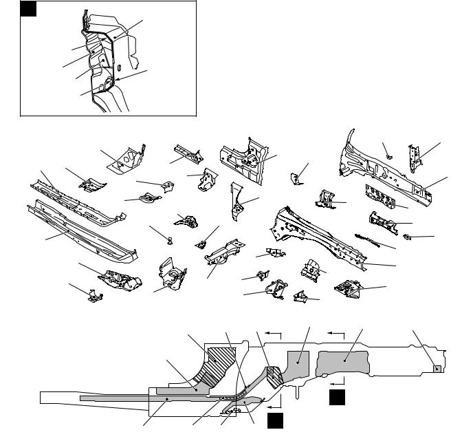
BODY COMPONENTS
|
|
|
|
|
|
|
|
|
|
M4010001000221 |
|
|
|
|
|
38 |
|
|
|
|
|
47 |
|
|
|
|
|
|
|
|
|
|
|
|
|
|
37 |
|
|
|
|
|
|
46 |
|
|
|
|
|
|
|
|
|
|
|
|
|
|
|
|
|
|
|
|
|
|
|
45 |
48 |
|
|
34 |
|
|
|
|
|
|
|
49 |
|
|
|
|
|
|
|
|
|
|
|
|
|
||
|
|
|
|
|
|
42 |
43 |
44 |
|
|
|
|
|
|
|
|
41 |
|
|
|
|
||
|
|
|
|
|
|
|
|
|
|
||
|
36 35 |
|
|
|
|
|
|
|
|
||
|
|
|
|
|
50 |
|
|
|
|
||
|
|
|
|
|
|
|
|
|
|
|
|
|
|
39 |
|
40 |
|
51 |
|
|
|
56 |
|
33 |
|
|
|
|
|
|
|
|
|
||
|
|
|
|
|
|
|
|
|
55 |
|
|
32 |
|
|
|
|
|
|
52 |
|
|
|
|
|
29 |
|
|
|
|
54 |
|
|
|
||
|
|
|
|
|
|
|
|
|
|
||
|
|
|
|
28 |
|
|
|
|
57 |
|
|
|
31 |
|
|
|
|
53 |
|
|
|
||
|
|
|
|
|
|
|
|
|
|
||
|
|
|
27 |
|
|
|
|
|
|
|
|
|
30 |
23 |
|
|
|
|
|
|
|
|
|
|
|
|
|
|
|
|
|
|
|
||
|
|
|
|
|
|
|
|
|
|
|
|
|
21 |
22 |
|
26 |
|
|
|
|
|
|
|
|
|
|
|
|
|
|
|
|
|
|
|
|
20 |
|
|
24 |
|
|
|
|
|
|
|
|
|
|
|
|
|
|
|
59 |
58 |
|
|
|
|
|
|
25* |
|
|
|
|
|
||
|
18 |
|
|
|
|
|
|
|
|
60 |
|
|
|
|
|
|
|
|
|
|
|
|
|
|
|
|
|
|
|
|
|
|
|
61 |
|
|
17 |
|
|
86 |
|
|
|
|
|
|
|
16 |
|
19 |
|
85 |
|
83 |
|
|
|
62 |
|
15 |
|
|
82 |
84 |
|
|
|
|
|||
|
81 |
|
|
|
|
|
|
|
|||
|
14 |
|
|
|
|
|
|
|
63 |
|
|
13 |
|
|
|
|
|
|
|
|
|
||
10* |
|
|
|
|
|
|
|
|
|||
|
|
|
|
|
|
|
|
|
64 |
||
|
|
9* |
|
|
|
|
|
|
|
|
|
12 |
|
|
|
|
|
|
|
|
|
|
|
11* |
6 |
|
|
|
|
|
|
70 |
|
66 |
65 |
|
|
|
|
|
|
|
|
||||
5 |
|
|
|
|
|
|
|
|
|||
4 |
|
|
|
|
|
72 |
|
|
|
||
|
8* |
|
|
|
|
68 |
|
|
|||
|
|
|
|
|
|
|
|
|
|||
|
7 |
|
|
|
|
73 |
71* |
67 |
|
||
|
|
80 |
|
|
|
|
|
|
|||
|
|
|
|
|
|
|
|
69 |
|
|
|
3* |
|
|
|
|
|
74* |
|
|
|
||
|
79 |
|
|
|
|
|
|
||||
|
|
76 |
|
|
|
|
|
||||
|
2 |
|
|
|
|
|
|
|
|||
|
|
|
|
|
|
|
|
|
|
||
|
|
78 |
|
|
|
|
|
|
|
||
|
1 |
|
|
|
|
|
|
|
|
||
|
77 |
|
75 |
|
|
|
|
||||
: Anti-corrosion steel panels |
|
|
|
|
|
||||||
|
|
|
|
|
|
|
|
|
|
||
: High-tensile steel panels (*: Indicates 590MPa-high-tensile steel panels.) |
|
|
|
AB301830AB |
|||||||
1. |
Front end crossmember |
4. |
Front end upper bar |
2. |
Hood lock stay |
5. |
Front upper bar side |
3. |
Front end beam |
6. |
Headlamp support brace upper |
|
|
BODY CONSTRUCTION |
1-3 |
|
|
|
BODY COMPONENTS |
|
|
7. |
Dash panel extension |
66. |
Rear floor crossmember D |
|
8. |
Front floor sidemember |
67. |
Rear floor sidemember |
|
9. |
Front floor sidemember reinforcement |
68. |
Rear floor crossmember C |
|
10. |
Front sidemember inner |
69. |
Rear floor crossmember B |
|
11. |
Front sidemember outer |
70. |
Front stringer |
|
12. |
Headlamp bracket |
71. |
Rear floor crossmember A |
|
13. |
Front fender shield |
72. |
Front floor crossmember rear |
|
14. |
Spring house panel |
73. |
Front floor pan |
|
15. |
Front upper frame inner |
74. |
Front floor side sill |
|
16. |
Front upper frame outer |
75. |
Front fender |
|
17. |
Dash panel crossmember upper |
76. |
Front floor crossmember front centre |
|
18. |
Dash panel |
77. |
Buttery tray stay |
|
19. |
Upper frame extension |
78. |
Buttery bracket |
|
20. |
Front deck |
79. |
Buttery tray |
|
21. |
Deck crossmember |
80. |
Foot rest bracket |
|
22. |
Guide bracket |
81. |
Front floor crossmember front |
|
23. |
Front pillar inner lower |
82. |
Back bone reinforcement |
|
24. |
Front pillar reinforcement outer lower |
83. |
Rear floor pan |
|
25. |
Side sill reinforcement |
84. |
Front fender bracket |
|
26. |
Centre pillar reinforcement outer |
85. |
Front fender bracket lower |
|
27. |
Centre pillar inner |
86. |
Front floor side sill inner front |
|
28.Front pillar reinforcement outer upper
29.Front pillar inner upper
30.Hood inner panel
31.Hood outer panel
32.Front door panel inner
33.Front door side door beam
34.Front door panel outer
35.Rear door panel inner
36.Rear door side door beam
37.Rear door panel outer
38.Roof panel
39.Front roof rail
40.Roof bow A
41.Roof bow B
42.Roof bow C
43.Roof bow D
44.Roof bow E
45.Rear roof rail
46.Tailgate panel inner
47Tailgate panel outer
48Quarter extension inner
49.Quarter inner panel
50.Roof reinforcement centre
51.Roof side rail inner
52Rear wheel house inner panel
53.Shield plate front
54.Shield plate rear
55Rear pillar reinforcement outer
56.Gate pillar reinforcement
57.Quarter extension outer
58Fuel filler door panel
59.Side outer panel
60.Rear end outer panel
61Rear end inner panel
62Quarter inner extension lower
63.Seat pan reinforcement
64.Rear floor side pan
65Rear floor side member rear extension
1-4 |
BODY CONSTRUCTION |
|
BODY MAIN CROSS-SECTIONAL VIEWS |
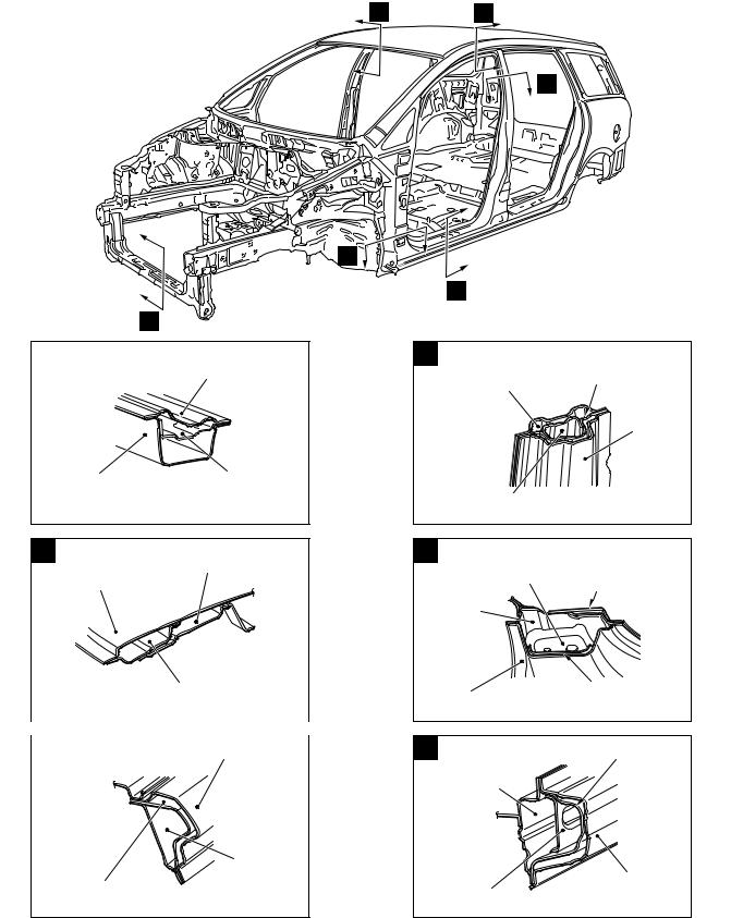
BODY MAIN CROSS-SECTIONAL VIEWS
M4010002000246
B C
D
E
F
A
AB300191AD
A |
Front end |
|
crossmember upper |
Front end |
Front end crossmember |
|
crossmember lower |
||
reinforcement |
||
|
||
|
AB300345AC |
B
Over head console bracket
Roof panel
|
Front roof rail inner |
|
AB300343AC |
|
|
C |
Side outer panel |
Side roof
rail inner
Front pillar
reinforcement outer upper
AB300344AC
D |
Centre pillar |
|
reinforcement outer |
|
Centre pillar inner |
|
Side outer |
|
panel |
Seat belt anchor
reinforcement
AB300346AC
EFront pillar reinforcement
bulkhead lower |
Front floor side sill |
|
reinforcement upper |
Front floor |
|
side sill |
|
inner front |
|
Side outer panel |
Front door hinge |
reinforcement lower |
|
|
AB300347AD |
F |
Side sill reinforcement |
Front floor |
|
side sill inner |
|
Side outer panel
Side sill
reinforcement front
AB300348AC

BODY CONSTRUCTION |
1-5 |
BODY MAIN CROSS-SECTIONAL VIEWS
J
G
H
I
K
L
AB300192AD
GFront pillar support (Drivers side)
Front pillar inner upper
Front pillar reinforcement |
Side outer panel |
||
outer upper |
|
AB300349AC |
|
|
|
|
|
H |
Seat belt reinforcement |
||
|
|
rear pillar |
|
|
|
|
Quarter inner |
|
|
|
panel |
|
Side outer |
|
|
|
panel |
|
|
|
|
Rear pillar reinforcement |
|
|
|
|
AB300351AE |
I |
Quarter inner panel |
Quarter inner |
|
|
extension upper |
||
|
|
|
|
Side |
|
outer panel |
|
Gate pillar |
Quarter outer |
extension |
|
reinforcement |
AB300352AC |
|
J
Roof panel
Rear roof rail inner
Rear roof rail outer
AB300350AC
K
Quarter inner panel
Side outer panel
Rear wheel house inner front panel
AB300353AC
L
Rear end panel |
Rear end |
inner |
panel outer |
Rear floor pan |
|
|
Tailgate striker |
|
reinforcement |
|
AB300354AC |
1-6 |
BODY CONSTRUCTION |
|
MAINTENANCE, SERVICEABILITY |
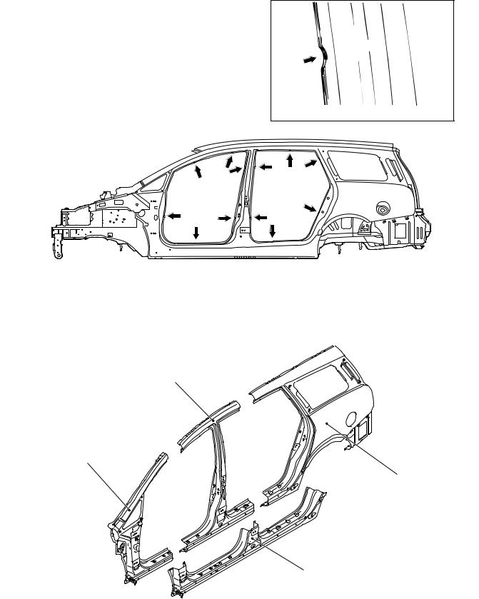
MAINTENANCE, SERVICEABILITY
M4010003000238
SIDE STRUCTURE
A panel positioning notch has been added on the door opening to improve assembling workability when replacing the panel.
Panel positioning notch AB301701AB
AB301702AB |
SIDE OUTER PANEL
The extra parts are supplied in 4 different cut forms as a result of employing the integrated side-frame side outer panel.
Centre pillar outer
Front pillar outer
Quarter outer
Floor side sill outer
AB301703AB
BODY CONSTRUCTION |
1-7 |
BODY CONSTRUCTION CHARACTERISTICS |
|
BODY CONSTRUCTION CHARACTERISTICS
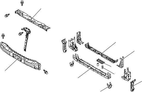
FRONT BODY
M4010010000263
HEADLAMP SUPPORT
•A front end beam with a large cross section has been adopted to improve safety upon impact.
3
2 
1
•The bolt-on front end beam, bolt-on hood lock stay and bolt-on front end upper bar are used to improve maintainability.
4
5
 6 8
6 8 

9
11 |
7 |
10
1.Front end beam
2.Hood lock stay
3.Front end upper bar
4.Front end crossmember upper
5.Headlamp support brace lower
6.Front end crossmember brace
7.Shipping bracket
8.Front end crossmember reinforcement
9.Front No2 crossmember pipe
10.Shipping reinforcement
11.Front end crossmember lower
AB301705AB
FENDER SHIELD
•The front frame structure is supported in three directions by the front floor side members with a large section, dash braces and dash upper crossmember (dash panel area) to improve body rigidity.
•An uneven thickness steel sheet* in which the sheet thickness is thicker in the forward part of the vehicle was employed for the front side member reinforcement to ensure safety upon impact and improve body rigidity.
NOTE: *: A steel sheet of varying thickness that is welded into one steel sheet.
1-8 |
BODY CONSTRUCTION |
|
|
|
BODY CONSTRUCTION CHARACTERISTICS |
|
|
Right side 7 |
B |
|
|
6 |
|
|
|
8 |
|
|
|
|
10 |
|
|
5 |
|
|
7 |
9 |
|
8 |
|
|
Light side |
6 |
|
4 |
|
||
11 |
|
|
|
|
|
|
10
3 |
11 |
4 |
|
2 |
12 |
|
|
A
1
3
5
1
AB301677AB
1.Front sidemember
2.Engine mount reinforcement (Right side)
3.Headlamp bracket
4.Front end upper bar side
5.Front fender shield
6.Front upper frame outer
7.Upper frame bulkhead front
8.Front upper frame inner
9.Power steering reservoir tank bracket (Right side)
10.Spring house bracket
11.Spring house panel
12.Relay box bracket (Left side)
The front part of the front side member has octagonal section that efficiently absorbs energy upon impact.
B |
Cowl top |
|
panel outer |
Spring house |
Cowl top |
panel inner |
|
bracket |
|
Spring house |
|
panel |
|
|
AB301689AB |
A |
The coupling between the cowl tops with a large |
|
cross section and the spring house brackets has |
|
been strengthened to heighten body rigidity of the |
|
suspension assembling support area and improve |
|
driving stability. |
Front sidemember |
Front sidemember |
inner |
outer |
|
AB301688AB |
BODY CONSTRUCTION |
1-9 |
BODY CONSTRUCTION CHARACTERISTICS |
|
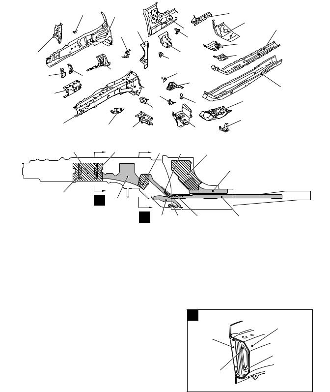
FRONT SIDEMEMBER REINFORCEMENT
Right side |
|
7 |
8 |
|
|
|
15 |
|
|
|
|
|
|||
|
|
|
|
|
|
|
16 |
|
|
|
10 |
|
14 |
19 |
|
|
|
|
9 |
|
|
13 |
|
|
|
|
|
|
|
17 |
|
|
|
|
|
|
|
|
|
6 |
|
|
|
|
12 |
18 |
|
|
|
|
|
|
11 |
|
|
5 |
|
4 |
3 |
|
26 |
|
|
|
|
|
|
25 |
|
||
|
|
|
|
|
|
20 |
|
|
2 |
|
|
27 |
|
|
|
|
|
|
|
|
21 |
||
|
|
|
|
|
|
24 |
|
|
|
|
|
28 |
|
|
|
|
|
|
|
|
|
22 |
|
|
1 |
|
|
|
|
|
|
|
30 |
29 |
|
|
23 |
|
|
|
|
|
|
AB302050AB |
|||
|
|
2 |
4 |
9 |
17 |
|
12 |
|
|
|
|
|
|
|
15 |
|
5 |
A |
3 |
|
|
|
|
|
|
|
|
|
|
||
|
|
|
B |
25 |
27 |
18 |
19 |
|
|
|
|
|
|
|
AB300245AC |
1.Front sidemember inner
2.Front sidemember inner reinforcement front
3.Pipe support front
4.Engine mounting bulkhead rear
5.Engine mounting bulkhead front
6.Headlamp support brace upper
7.Brake hose bracket
8.Front sidemember outer
9.Kick up reinforcement
10.Dash brace
11.Accel stopper bracket (R.H. drive vehicles)
12.Front floor side sill inner reinforcement upper
13.Hood opener bracket (R.H. drive vehicles)
14.Front floor side sill inner front
15.Front floor side sill inner reinforcement lower
16.Dash panel extension
17.Front floor sidemember reinforcement upper
18.Front floor sidemember reinforcement middle (R.H. drive vehicles)
19.Front floor sidemember reinforcement
20.Front floor sidemember
21.Suspension crossmember bracket rear
22.Dash crossmember extension lower
23.Front sidemember brace lower
24.Pipe nut
25.Pipe support rear
26.Accel pedal bracket (R.H. drive vehicles)
27.Stay reinforcement
28.Dash crossmember upper reinforcement extension (R.H. drive vehicles)
29.Dash crossmember extension upper
30.Suspension crossmember bracket front
A
1
8
4
2
AB301690AB
1-10 |
BODY CONSTRUCTION |
|
BODY CONSTRUCTION CHARACTERISTICS |
B |
1 |
|
|
|
|
|
|
|
|
|
|
|
|
|
|
|
|
|
10 |
|
|
|
|
|
|
|
|
8 |
9 |
|
|
|
|
|
|
|
19 |
|
|
|
|
|
|
|
|
3 |
|
|
|
|
|
|
|
|
|
AB302054AB |
|
|
|
|
|
|
Light side |
|
|
|
|
|
14 |
15 |
|
|
6 |
|
|
|
|
|
||
|
|
|
|
|
|
|
||
|
|
|
12 |
|
|
|
|
|
|
5 |
9 |
|
13 |
|
|
|
|
4 |
|
|
|
|
|
|||
|
|
|
|
|
16 |
|||
|
8 |
10 |
|
|
|
|
|
|
|
7 |
31 |
|
11 |
|
20 |
|
|
|
|
|
|
|
19 |
|||
|
|
30 |
|
|
|
|
||
|
32 |
|
|
|
|
|
18 |
|
3 |
|
|
|
|
|
|
|
17 |
|
|
|
|
|
|
|
21 |
|
|
2 |
|
|
28 |
|
|
|
|
|
|
|
|
|
|
22 |
||
|
|
|
|
|
|
|
||
|
|
|
|
|
|
25 |
|
|
|
1 |
|
29 |
27 |
|
|
23 |
|
|
|
|
|
|
||||
|
33 |
|
|
26 |
|
24 |
|
AB302049AB |
|
|
|
|
|
|
|
||
|
|
|
|
|
|
|
|
|
|
|
10 |
5 |
13 |
20 |
18 |
|
17 |
|
|
|
|
|
|
|
|
|
|
|
9 |
|
|
|
|
|
|
|
|
|
|
|
|
A |
|
|
|
4 |
7 |
30 |
B |
|
|
|
|
|
31 |
|
|
|
AB302053AB |
|||
|
|
|
|
|
|
|
|
|
1. |
Dash crossmember extension lower |
16. |
Front sidemember outer |
2. |
Suspension crossmember bracket rear |
17. |
Towing reinforcement |
3. |
Front floor sidemember |
18. |
Transmission mounting reinforcement |
4. |
Front floor sidemember reinforcement |
19. |
Front sidemember outer reinforcement (L.H. drive |
5. |
Front floor sidemember reinforcement upper |
|
vehicles) |
6. |
Dash panel extension |
20. |
Pipe support front |
7. |
Front floor sidemember reinforcement middle (L.H. |
21. |
Front sidemember inner reinforcement (L.H. drive |
|
drive vehicles) |
|
vehicles) |
8. |
Dash crossmember upper reinforcement extension |
22. |
Front sidemember inner |
|
(L.H. drive vehicles) |
23. |
Battery bracket |
9. |
Front floor side sill inner reinforcement lower |
24. |
Transmission mounting stay front |
10. |
Front floor side sill inner reinforcement upper |
25. |
Transmission mounting gusset |
11. |
Dash brace |
26. |
Transmission mounting bracket |
12. |
Front floor side sill inner front |
27. |
Transmission mounting stay rear |
13. |
Kick up reinforcement |
28. |
Suspension crossmember bracket front |
14. |
Brake house bracket |
29. |
Dash crossmember extension upper |
15. |
Headlamp support brace upper |
30. |
Stay reinforcement |
|
|
BODY CONSTRUCTION |
1-11 |
|
|
BODY CONSTRUCTION CHARACTERISTICS |
|
31. |
Pipe support rear |
B |
|
32 |
Pipe nut |
|
|
|
|
||
33. Front sidemember brace lower |
4 |
|
|
|
A |
|
|
|
|
11 |
|
|
|
22 |
|
|
|
16 |
|
|
|
18 |
|
|
|
20 |
|
|
|
13 |
|
|
|
|
|
|
22 |
16 |
AB302056AB |
|
|
||
|
|
|
|
|
|
FRONT DECK |
|
|
|
AB302055AB |
|
|
|
|
4 |
|
|
|
6 |
|
|
|
7 |
|
3 |
|
5 |
|
|
8 |
|
|
|
|
|
|
|
|
9 |
|
|
2 |
10 |
|
|
|
|
|
|
|
11 |
1 |
|
|
12 |
|
|
|
AB301706AB
1. |
Cowl top panel front |
7. |
Cowl top bulkhead C |
2. |
Cowl top panel inner |
8. |
Cowl top gusset side |
3. |
Wiper bracket A |
9. |
Front upper frame extension inner |
4. |
Cowl top bulkhead A |
10. |
Upper frame bulkhead rear |
5. |
Cowl top panel outer |
11. |
Front upper frame extension outer |
6. |
Cowl top bulkhead B |
12. |
Fender bracket |

1-12 |
|
|
BODY CONSTRUCTION |
|
|
|
|
BODY CONSTRUCTION CHARACTERISTICS |
|
||
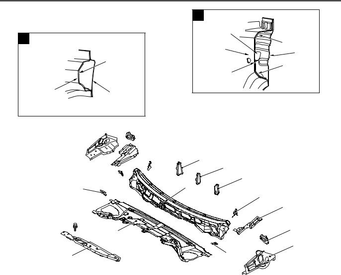
DASH PANEL |
|
|
|
|
|
|
|
4 |
|
6 |
7 |
|
|
5 |
|
||
|
|
|
|
||
|
|
|
|
|
|
|
3 |
|
|
|
|
1 |
2 |
|
|
|
|
|
|
|
|
8 |
|
|
|
|
|
|
|
11 |
10 |
9 |
|
||
|
|
AB301685AB
1.Dash crossmember upper
2.Dash crossmember reinforcement upper
3.Dash panel plate (RH drive vehicles, A/T lever type)
4.Dash panel
5.Dash crossmember lower
6.Accel pedal upper bracket (LH drive vehicles)
7.Clutch pedal support bracket (Vehicle for M/T)
8.Dash panel reinforcement
9.Clutch pedal stopper bracket (RH drive vehicles, M/T)
10.Accel pedal bracket (LH drive vehicles)
11.Steering shaft bracket
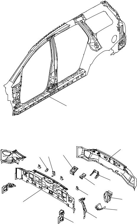
SIDE BODY
M4010011000233
SIDE STRUCTURE
•An uneven thickness steel sheet* in which the sheet thickness is thicker in the order of the upper section, rear section, and lower section was employed for the side outer panel to ensure safety upon side impact.
•The rear wheel houses each consist of a front and a rear panel, and thick steel plates are used for the rear wheel house panels where the rear suspensions are installed, in order to heighten the body rigidity and improve driving stability.
NOTE: *: A steel sheet of varying thickness that is welded into one steel sheet.

BODY CONSTRUCTION |
1-13 |
BODY CONSTRUCTION CHARACTERISTICS |
|
|
|
27 |
28 |
29 |
|
31 |
33 |
|
|
|
|
|
|
|
|
16 |
25 |
26 |
|
|
30 |
|
34 |
|
|
|
|
|
|
32 |
|
|
|
24 |
|
|
|
|
|
|
|
|
|
|
|
|
10 |
|
|
|
17 |
21 |
23 |
35 |
37 |
|
|
|
|
36 |
38 |
|||
|
|
14 |
|
19 |
|
|||
|
|
15 |
20 |
|
||||
|
|
22 |
|
|
||||
|
|
|
18 |
|
|
|||
|
13 |
|
|
|
51 |
|
||
|
|
|
|
|
|
|||
|
|
|
|
|
|
|
||
11 |
12 |
|
|
|
|
|
50 |
|
|
|
|
|
|
|
|
||
9 |
6 |
|
|
|
|
|
|
|
8 |
|
|
|
|
49 |
|
|
|
|
|
|
47 |
|
|
|
||
43 |
|
45 |
48 |
|
|
|
||
|
44 |
|
|
|
||||
7 |
|
|
46 |
|
40 |
|
39 |
|
42 |
|
|
|
|
||||
|
|
|
|
|
|
|
||
5 |
|
|
|
|
|
|
|
|
|
|
|
|
|
|
|
|
|
4 |
|
|
|
|
|
|
|
|
3 |
|
|
|
|
|
|
|
|
2 |
|
|
|
|
|
|
|
|
1 |
|
41 |
|
|
|
|
|
AB301697AB |
1.Front fender lower bracket
2.Front door hinges reinforcement lower
3.Front pillar reinforcement bulkhead lower
4.Front pillar reinforcement outer lower
5.Front door checker bulkhead
6.Front door hinges reinforcement upper
7.Front pillar inner lower
8.Deck crossmember bracket
9.Instrument panel side bracket
10.Front pillar inner upper
11.Front pillar support (Driver’s side)
12.Front pillar reinforcement outer upper (Passenger’s side)
13.Centre pillar inner
14.Seat belt anchor reinforcement
15.Rear door hinges reinforcement upper
16.Side roof rail inner
17.Centre pillar reinforcement outer
18.Third seat anchor reinforcement
19.Rear wheel house inner front panel
20.Shock absorber reinforcement
21.Rear wheel house inner rear panel
22.Rear door striker reinforcement
23.Seat belt reinforcement lower second
24.Seat belt reinforcement rear pillar
25.Rear pillar reinforcement outer
26.Quarter inner panel
27.Radio tuner amplifier bracket (Right side)
28.TV tuner amplifier bracket (Left side)
29.Quarter inner extension upper
30.Seat belt reinforcement lower third
31.Seat belt reinforcement upper
32.Quarter inner extension
33.Gate pillar upper reinforcement
34.Gate pillar reinforcement
35.Fuel filler neck bracket (Left side)
36.Gas spring reinforcement
37.Quarter outer extension
38.Tailgate dumper reinforcement side
39.Side outer panel
40.Fender bracket
41.Side sill reinforcement
42.Side sill reinforcement front
43.Seat belt front anchor reinforcement
44.Side sill reinforcement centre
45.Rear door check bulkhead
46.Side sill bulkhead rear
47.Harness bracket
48.Shock absorber support
49.Rear seat belt reinforcement wheel house
50.Shield plate front
51.Shield plate rear
SIDE STRUCTURE REINFORCEMENT
An uneven thickness steel sheet* in which the sheet thickness is thicker in the forward part of the vehicle was employed for the side sill reinforcement to ensure safety upon side impact.
NOTE: *: A steel sheet of varying thickness that is welded into one steel sheet.
1-14 |
BODY CONSTRUCTION |
|
BODY CONSTRUCTION CHARACTERISTICS |
Side sill reinforcement
AB301707AB
REAR BODY
M4010012000203
REAR END CROSSMEMBER
5
2 |
3 |
4 |
|
|
|
|
|
6 |
|
|
|
7 |
|
|
|
10 |
|
1 |
|
8 |
|
|
|
|
|
|
|
9 |
|
|
|
11 |
|
|
|
12 |
|
|
|
AB301708AB |
1. |
Rear end panel inner |
8. Jack rear bracket A |
|
2. |
Heat protector bracket |
9. Jack rear bracket B |
|
3. |
Muffler hanger bracket rear |
10. |
Bumper bracket |
4. |
Tailgate striker reinforcement |
11. Rear floor side brace |
|
5. |
Rear end panel outer |
12. |
Quarter inner extension lower |
6.Jack rear bulkhead
7.Spare tyre reinforcement rear end
BODY CONSTRUCTION |
1-15 |
BODY CONSTRUCTION CHARACTERISTICS |
|
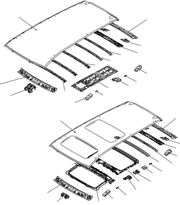
ROOF
Except for sun roof
3
2
1 |
Vehicles with sun roof
M4010013000217
|
16 |
14 |
15 |
AB300304 |
|
|
 13
13
10 |
9 |
|
12 |
8 |
|
|
|
11 |
3


 AB300305
2 |
8 |
|
|
21 |
11 |
20 |
4
5 6
7
8
4
|
|
|
5 |
|
|
|
6 |
|
|
|
7 |
|
|
15 |
16 |
|
|
|
|
|
9 |
8 |
|
|
|
|
|
18 |
17 |
|
|
|
|
|
|
19 |
|
|
|
AB301710AB
1. |
Overhead console bracket |
11. |
Roof rack reinforcement front (Vehicles with roof rail) |
2. |
Front roof rail inner |
12. |
Roof bow A |
3. |
Roof panel |
13. |
Roof bow B |
4. |
Rear roof rail outer |
14. |
Roof bow centre |
5. |
Tailgate hinge reinforcement |
15. |
Roof bow D |
6. |
Rear roof rail inner |
16. |
Roof bow E |
7. |
Roof rack reinforcement rear (Vehicles with roof rail) |
17. |
Set bracket rear |
8. |
Roof carrier bracket |
18. |
Roof reinforcement rear |
9. |
Roof rack reinforcement centre (Vehicles with roof |
19. |
Set bracket front |
|
rail) |
20. |
Roof reinforcement front |
10. |
Roof centre reinforcement |
21. |
Room lamp bracket |
1-16 |
BODY CONSTRUCTION |
|
BODY CONSTRUCTION CHARACTERISTICS |
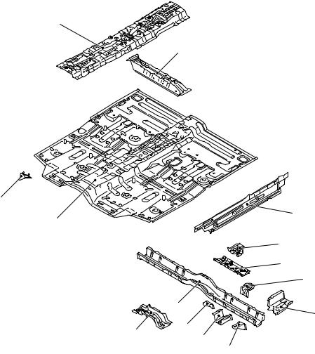
UNDER BODY
M4010014000265
FRONT FLOOR
3
4
2 |
|
|
1 |
|
5 |
|
|
|
|
|
6 |
|
|
7 |
|
|
8 |
|
13 |
9 |
|
|
|
14 |
12 |
11 |
|
||
|
|
|
|
|
10 |
1.Front floor pan
2.Foot rest bracket (R.H. drive vehicles)
3.Backbone reinforcement
4.Front floor crossmember front
5.Front floor side sill inner
6.Front floor crossmember rear bulkhead
7.Front floor crossmember rear reinforcement
8.Fuel tank support bracket front
9.Front floor sidemember extension rear
10.Front seat reinforcement rear side
11.Front floor sidemember extension front
12.Front seat anchor reinforcement centre
AB301673AB
13. Front floor crossmember rear
14 Front floor crossmember front centre
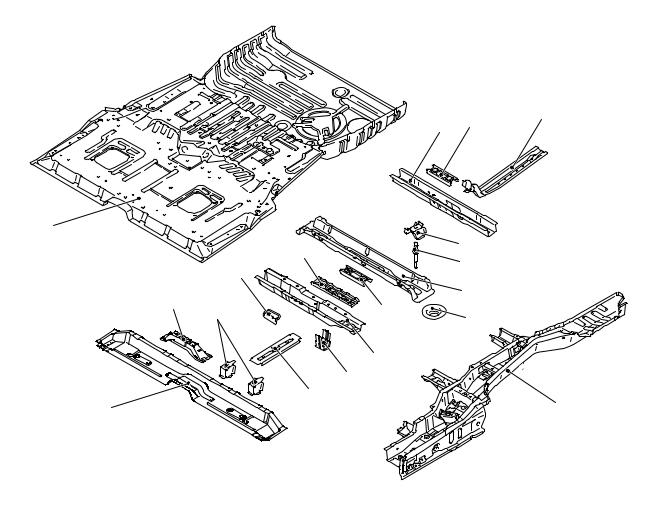
REAR FLOOR
•An uneven thickness steel sheet* in which the sheet thickness is thicker in the forward part of the vehicle was employed for the rear floor side member to ensure safety upon impact.
NOTE: *: A steel sheet of varying thickness that is welded into one steel sheet.
BODY CONSTRUCTION |
1-17 |
BODY CONSTRUCTION CHARACTERISTICS |
|
|
|
|
|
|
5 |
6 |
7 |
|
|
|
|
|
|
||
|
|
|
|
|
|
|
|
4 |
|
|
|
|
|
8 |
|
|
|
|
13 |
|
|
|
|
|
|
|
|
|
9 |
|
|
|
|
16 |
|
|
|
|
|
|
|
|
|
|
|
|
|
2 |
|
|
|
|
|
10 |
|
3 |
|
|
12 |
|
11 |
|
|
|
|
|
|
|
|||
|
|
|
|
|
|
|
|
|
|
|
|
14 |
|
|
|
|
|
|
|
15 |
|
|
|
1 |
|
|
17 |
|
|
|
18 |
|
|
|
|
|
|
||
|
|
|
|
|
|
|
AB301667AB |
1. |
Rear floor crossmember A |
12. |
Seat anchor reinforcement B |
2. |
Seat anchor reinforcement front centre A |
13. |
Rear floor crossmember centre reinforcement B |
3. |
Seat anchor front reinforcement |
|
(Seven-passenger model) |
4. |
Rear floor pan |
14. |
Rear floor crossmember B |
5. |
Rear floor crossmember D |
15. |
Fuel tank support bracket rear |
6. |
Seat anchor reinforcement D |
16. |
Flange reinforcement (Seven-passenger model) |
7. |
Seat pan reinforcement |
17. |
Front stringer |
8. |
Rear suspension crossmember bulkhead |
18. |
Rear floor sidemember |
9.Mounting bolt
10.Rear floor crossmember C
11.Spring sheet
1-18 |
BODY CONSTRUCTION |
|
BODY CONSTRUCTION CHARACTERISTICS |
REAR FLOOR SIDEMEMBER
REINFORCEMENT
|
|
|
10 |
12 |
13 |
|
|
|
|
7 |
|
|
|
||
|
|
|
|
|
|
|
|
|
|
|
9 |
11 |
14 |
|
|
|
|
|
|
|
|
||
|
|
|
|
|
|
|
|
|
6 |
|
8 |
|
15 |
|
|
|
|
|
|
|
|
||
|
|
|
|
|
|
|
|
|
|
5 |
|
20 |
16 |
|
|
|
|
|
|
|
|
||
|
|
4 |
|
21 |
17 |
|
|
|
|
|
|
|
|
|
|
|
3 |
2 |
|
22 |
18 |
|
|
|
|
|
|
|
|||
|
|
|
|
23 |
19 |
|
|
|
|
1 |
|
|
|
|
|
|
|
25 |
24 |
|
|
AB301668AB |
|
|
|
|
|
|
|||
|
|
7 |
9 |
|
20 |
|
|
2 |
25 |
5 |
|
|
|
|
|
|
|
|
|
|
|
||
|
|
|
|
|
|
|
|
|
|
|
|
|
14 |
|
13 |
|
|
|
11 |
A |
12 |
B |
|
|
|
|
|
|
|||
|
|
|
|
|
|
AB301675AB |
|
1.Rear floor sidemember extension front
2.Tie down hook plate
3.Fuel tank support bracket
4.Pipe nut
5.Pipe support front
6.Rear floor crossmember extension B
7.Seat anchor rear reinforcement (Seven-passenger model right side)
8.Seat anchor rear reinforcement (Except for seven passenger model right side)
9.Rear floor sidemember front bulkhead
10.Rear floor crossmember extension D
11.Rear floor sidemember reinforcement
12.Third seat anchor reinforcement
13.Rear floor sidemember rear bulkhead (Left side)
14.Rear floor sidemember extension rear
15.Rear floor side pan
16.Muffler hanger bracket rear (Right side)
17.Heat protector bracket (Right side)
18.Spare tyre support (Left side)
19.Shipping bracket (Right side)
20.Rear floor sidemember
21.Brake hose bracket
22.Rear floor side sill inner
23.Jack up side reinforcement
24.Sidemember front bulkhead
25.Rear suspension crossmember stopper bracket
A
15
12 |
20
11
AB300434AC
B
15
13
 20 14
20 14
AB300435AC
BODY CONSTRUCTION |
1-19 |
BODY CONSTRUCTION CHARACTERISTICS |
|
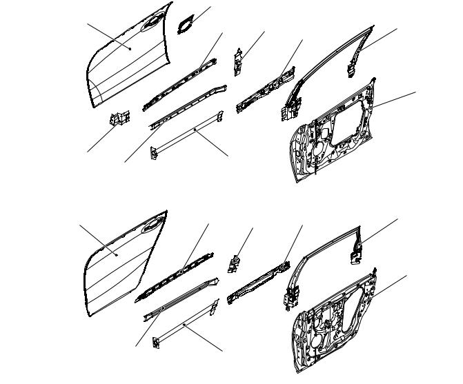
DOOR
M4010015000213
• An uneven thickness steel sheet* in which the sheet thickness is thicker in the forward part of the vehicle was employed for the inner panel to improve rigidity.
• The front and rear side door beam was located in the bumper position of the vehicle to improve cabin protection upon side impact.
•A belt line inner reinforcement has been adopted to improve cabin protection upon impact.
•The bottom section of the door sash pillar was enlarged and the couplings between the hinge, latch and door sash were strengthened to improve sash rigidity.
NOTE: *: A steel sheet of varying thickness that is welded into one steel sheet.
Front door |
|
2 |
|
|
|
1 |
3 |
4 |
6 |
|
|
|||
|
|
|
|
5 |
7
10 |
8 |
|
9 |
AB301700AB
Rear door
11 |
12 |
13 |
14 |
15 |
16
18 |
17 |
|
|
|
AB301699AB |
1. |
Front door outer panel |
10. |
Front door hinge upper reinforcement |
2. |
Front door outside handle reinforcement |
11. |
Rear door outer panel |
3. |
Front door belt line outer reinforcement |
12. |
Rear door belt line outer reinforcement |
4. |
Front door latch reinforcement |
13. |
Rear door latch reinforcement |
5. |
Front door belt line inner reinforcement |
14. |
Rear door belt line inner reinforcement |
6. |
Front door window sash |
15. |
Rear door window sash |
7. |
Front door inner panel |
16. |
Rear door inner panel |
8. |
Front side door beam |
17. |
Rear side door beam |
9. |
Front door outer stiffener |
18. |
Rear door outer stiffener |
1-20 BODY CONSTRUCTION
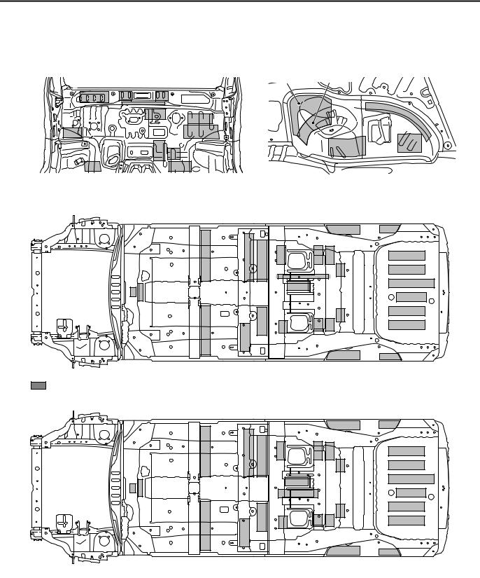
SILENCER APPLICATION LOCATIONS
SILENCER APPLICATION LOCATIONS
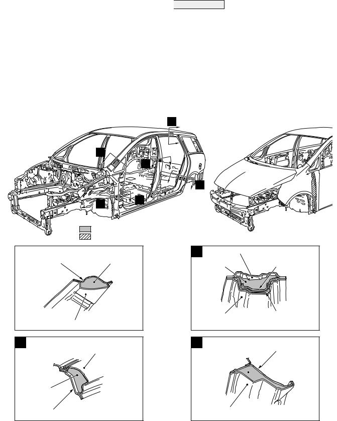
Sound insulation was improved by using a spray-type anti-vibration agent on the cabin side of the dash panel, rear wheel house and rear floor.
M4010005000278
Use a melting sheet for repair.
<Left side> |
<Right side> |
|
AB300368 |
|
AB301712AB |
Dash panel |
Rear wheel house inner |
Six-passenger model |
AB301714AB |
: 3.2 mm thick melting sheet and RSS (Place two 1.6 mm melting sheet one on top of another.) |
Seven-passenger model |
AB301713AB |
NOTE: ( ) indicates the number of melting sheets that are used for repair.
BODY CONSTRUCTION |
1-21 |
LOCATIONS USING URETHANE FOAM AND FOAM MATERIAL |
|
LOCATIONS USING URETHANE FOAM AND FOAM
MATERIAL
•Introduction of noise was prevented by adding acoustic foam materials inside the front pillar, centre pillar, side roof rail and wheel house arch.
•Introduction of noise was prevented by inserting urethane foam inside the front pillar, centre pillar and front fender.
M4010007000177

 CAUTION
The foam materials may burn when heated. Always observe the following instructions.
•Never use a gas burner or burn the areas using foam materials.
•When cutting the parts using foam materials, ensure to use tools (air saw, etc.) that do not generate fire.
•If there is residual foam materials remaining on the cut section (body side) then weld after removing the foam materials from periphery of the welding area.
|
|
B |
|
A |
|
|
|
C |
|
|
D |
|
E |
F |
|
|
|
AB300416 |
: Acoustic foam |
AB300490 |
: Urethane foam |
|
|
|
AB300554AC |
|
|
|
A |
Front pillar |
Acoustic foam |
|
inner upper |
material |
|
||
|
|
Side outer panel
AB300446AC
B
Side outer panel
Acoustic foam material
Roof side rail inner
AB300448AC
C |
Centre pillar inner |
Seat belt anchor Acoustic foam reinforcement
material
Side outer panel |
Centre pillar |
|
reinforcement outer |
||
|
||
|
AB300447AC |
D
Quarter inner panel
Acoustic foam material 
Side outer panel
AB300449AC

1-22 |
|
BODY CONSTRUCTION |
|
STIFFENER AND DAMP SHEET APPLICATION LOCATIONS |
|
E |
|
F |
|
Front pillar |
Side outer panel |
|
Seat belt front |
|
Front pillar inner lower |
reinforcement |
|
|
outer lower |
anchor reinforcement |
Urethane foam |
|
Urethane |
|
foam |
|
|
|
|
Front door hinge |
Front floor side |
|
sill inner front |
|
|
reinforcement |
Side sill |
|
lower |
|
|
|
reinforcement |
|
|
AB300450AC |
|
|
AB300451AC |
|
STIFFENER AND DAMP SHEET APPLICATION LOCATIONS
Sound insulation was improved with anti-vibration effects and heightening surface rigidity with a stiffener on the inner side of the side outer panel and the tailgate outer panel, as well as a damping sheet adhered to the inner side of the front door and the rear door outer panel.
M4010008000192
NOTE: The main contents of a stiffener are epoxy resin. It comes in a sheet form and contains a mixture of glass fibre and filler, and cures (stiffens) when heated. It is used to improve the rigidity of the outer plate.
Stiffener
Damp sheet
Stiffener
AB301882AB
Front door |
|
Tailgate |
|
|
|
|
|
|
Damp sheet |
Stiffener |
AB301881AB |

2-1
GROUP 2
BODY DIMENSIONS
CONTENTS
BODY DIMENSIONS AND MEASUREMENT METHODS . . . . . . . . . . . . . . . . . . . . . 2-2
TYPE A (PROJECTED DIMENSIONS)
. . . . . . . . . . . . . . . . . . . . . . . . . . . . . . . . . |
2-3 |
UNDER BODY . . . . . . . . . . . . . . . . . . . . . . |
2-3 |
SUSPENSION INSTALLATION DIMENSIONS |
2-5 |
. . . . . . . . . . . . . . . . . . . . . . . . . . . . . . . . . . . . . . |
TYPE B (ACTUAL-MEASUREMENT |
|
DIMENSIONS). . . . . . . . . . . . . . . . . . . |
2-7 |
UNDER BODY. . . . . . . . . . . . . . . . . . . . . . . |
2-7 |
SUSPENSION INSTALLATION DIMENSIONS |
2-8 |
. . . . . . . . . . . . . . . . . . . . . . . . . . . . . . . . . . . . . . |
|
FRONT BODY . . . . . . . . . . . . . . . . . . . . . . . |
2-10 |
SIDE BODY . . . . . . . . . . . . . . . . . . . . . . . . . |
2-12 |
REAR BODY . . . . . . . . . . . . . . . . . . . . . . . . |
2-13 |
INTERIOR . . . . . . . . . . . . . . . . . . . . . . . . . . |
2-14 |
2-2 |
BODY DIMENSIONS |
|
BODY DIMENSIONS AND MEASUREMENT METHODS |
BODY DIMENSIONS AND MEASUREMENT METHODS
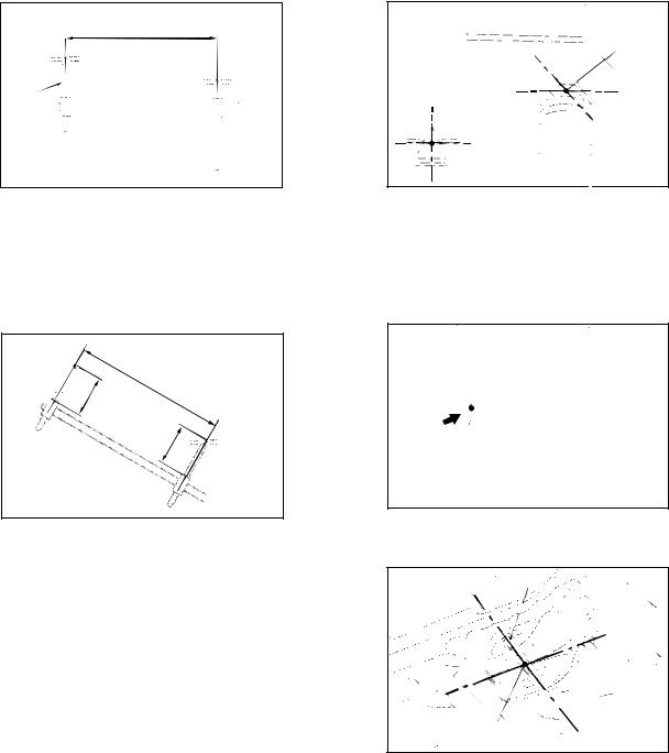
Projected dimension
Height
Probe
AB100778AB
1.Type A (projected dimensions)
Indicates the dimension when a measurement location is projected onto the plane.
The difference in height of the measurement points should be taken into consideration when measuring.
M4020001000255 |
Centre of hole |
AB100780AD |
3.Insert the tracking gauge probes securely into the measurement holes.
4.When the standard dimensions in the illustration are enclosed by rectangle, this indicates that the symmetrical left and right positions have the same dimensions.
Actual- 


 measured


 A
A
A'
dimension
AB100781AB
AB100779AB
2.Type B (actual-measurement dimensions)
Indicates the actual distance between the measurement points.
Measure using a tracking gauge or a measuring tape, etc.
NOTE:
•Make the lengths of the tracking gauge probes the same (A=A’).
•Do not bend or twist the measuring tape.
5.When using a notch for dimension measurement, set the measuring point at the centre of the notch.
Bolt |
Measurement point |
AB100782AB |
6.When measuring the suspension mounting arm, or link mounting position, use the suspension mounting bolt, etc. (Type B only)
7.The body centre points are shown for the purpose of checking the position of the left and right symmetry location.
BODY DIMENSIONS |
2-3 |
TYPE A (PROJECTED DIMENSIONS) |
|
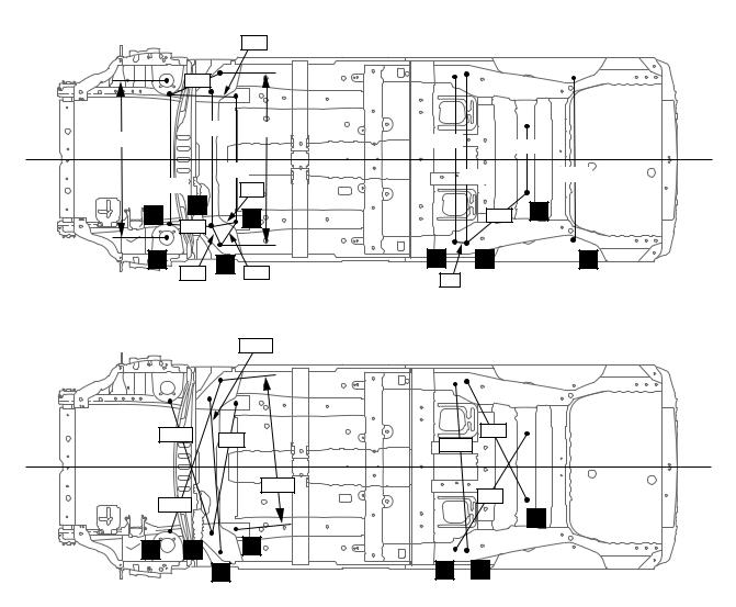
TYPE A (PROJECTED DIMENSIONS)
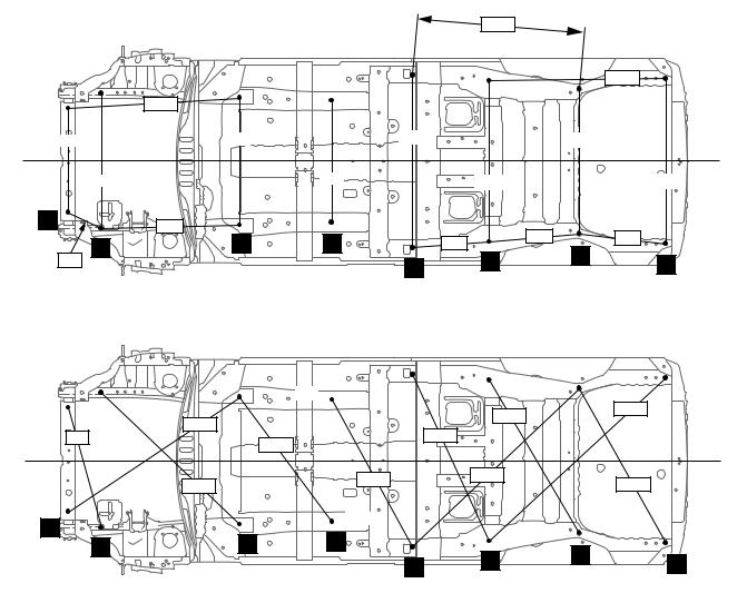
UNDER BODY
|
|
M4020005000536 |
|
|
|
|
|
|
|
|
1200 |
|
mm |
|
|
|
|
|
|
1261 |
|
1230 |
|
|
|
|
|
740 |
908 |
1240 |
|
1030 |
|
|
960 |
|
870 |
|
1160 |
|
1180 |
1 |
979 |
|
|
642 |
|
628 |
2 |
3 |
4 |
558 |
|
||
6 |
7 |
|
||||
271 |
|
5 |
|
8 |
||
|
|
|
|
|||
|
|
|
|
|
|
AB301815AB |
|
|
|
|
1268 |
|
1721 |
|
1478 |
|
|
|
|
|
885 |
|
1323 |
|
|
|
|
|
1117 |
|
|
|
||
|
|
|
|
|
|
|
|
1353 |
1216 |
|
1648 |
|
1269 |
|
|
|
|
|||
|
|
|
|
|
||
1 |
3 |
4 |
|
|
|
|
2 |
|
6 |
7 |
8 |
||
|
|
5 |
|
|||
|
|
|
|
|||
|
|
|
AB301816AB |
|
|
|
|
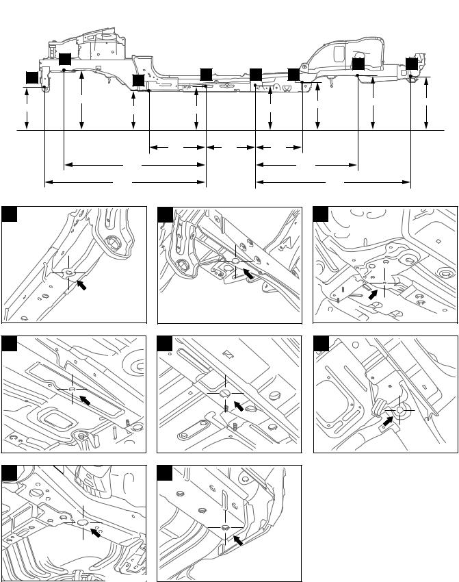
No. |
Standard measurement point |
Hole shape |
Size mm |
1* |
Centre of front end crossmember brace positioning hole |
Round |
12 |
|
|
|
|
2* |
Centre of front sidemember inner positioning hole |
Round |
25 |
|
|
|
|
3* |
Centre of suspension crossmember stay mounting hole |
Round |
14 |
|
|
|
|
4* |
Centre of front floor sidemember positioning hole |
Round |
16 |
|
|
|
|
5* |
Centre of rear floor sidemember extension front positioning hole |
Round |
25 |
|
|
|
|
6* |
Centre of rear floor sidemember water draining hole |
Round |
25 |
|
|
|
|
7* |
Centre of rear floor sidemember positioning hole |
Round |
35 |
8* |
Centre of hichmember mounting hole (This hole also serves as a |
Round |
16 |
|
shipping bracket mounting hole on left side.) |
|
|
|
|
|
|
NOTE: The * mark indicates the mounting position for the frame centring gauge.
2-4 |
BODY DIMENSIONS |
|
TYPE A (PROJECTED DIMENSIONS) |
|
|
|
|
|
|
|
mm |
|
2 |
|
|
|
|
7 |
8 |
|
|
4 |
5 |
|
6 |
||
1 |
3 |
|
|
|
|||
|
|
|
|
|
|
||
|
|
|
|
|
|
|
|
128 |
330 |
|
|
165 |
219 |
282 |
269 |
100 |
150 |
|
|||||
|
|
|
|||||
|
|
|
|
||||
|
676 |
605 |
|
557 |
|
|
|
|
1655 |
|
|
|
1195 |
|
|
|
1903 |
|
|
|
|
1818 |
|
|
|
|
|
|
|
|
AB301817AB |
1 |
2 |
|
|
|
3 |
|
|
AB300200AB |
AB300201AB |
AB300195AB |
4 |
5 |
6 |
AB300196AB |
AB300197AB |
AB300194AB |
7 |
8 |
|
AB301814AB |
AB300199AB |
BODY DIMENSIONS |
2-5 |
TYPE A (PROJECTED DIMENSIONS) |
|
SUSPENSION INSTALLATION |
|
|
|
||||
DIMENSIONS |
|
|
|
M4020013000467 |
|
|
|
|
|
|
|
|
|
|
|
|
|
|
|
|
|
|
mm |
|
|
|
|
474 |
|
|
|
|
|
392 |
|
|
|
|
|
1145 |
|
970 |
1250 |
1192 |
|
|
|
|
|
|
|
|
480 |
||
|
|
|
|
|
|
|
|
|
|
|
908 |
|
1230 |
1165 |
|
|
940 |
|
|
181 |
|
||
|
|
|
|
|
|
||
|
|
12 |
|
|
|
|
|
11 |
|
3 |
|
574 |
16 |
||
297 |
|
|
|||||
|
|
|
|
|
|
|
|
9 |
154 |
13 |
206 |
14 |
15 |
10 |
|
|
|
89 |
|
|
|||
|
|
|
|
|
|
|
|
|
|
|
|
|
|
|
AB301820AB |
|
|
|
|
1112 |
|
|
|
|
1000 |
956 |
|
959 |
|
||
|
1214 |
|
|||||
|
|
|
|
||||
|
|
|
|
|
|
||
|
|
|
|
1085 |
|
985 |
|
|
1153 |
|
|
|
|
||
|
|
|
|
|
16 |
||
|
|
|
|
|
|
|
|
11 |
|
12 |
|
3 |
|
|
|
|
|
|
13 |
|
14 |
15 |
|
|
|
|
|
|
|
|
AB301821AB |
No. |
Standard measurement point |
Hole shape |
Size mm |
3 |
Centre of suspension crossmember stay mounting hole |
Round |
14 |
|
|
|
|
9 |
Centre of front shock absorber mounting hole |
Round |
104.6 |
|
|
|
|
10 |
Centre of rear shock absorber mounting hole |
Round |
22 |
|
|
|
|
11 |
Tip of front suspension crossmember mounting bolt |
− |
− |
|
|
|
|
12 |
Centre of suspension crossmember positioning hole |
Round |
15.5 |
|
|
|
|
13 |
Centre of suspension crossmember stay mounting hole |
Round |
16 |
|
|
|
|
14 |
Centre of rear suspension stopper front mounting hole |
Round |
11 |
|
|
|
|
15 |
Centre of rear suspension crossmember mounting hole |
Round |
15.5 |
|
|
|
|
16 |
Tip of rear suspension crossmember mounting bolt |
− |
− |
|
|
|
|
 Loading...