


 Loading...
INVERTER
Plug-in option
FR-A8NF
INSTRUCTION MANUAL
FL remote communication function
PRE-OPERATION INSTRUCTIONS |
1 |
|
|
|
|
INSTALLATION |
2 |
|
|
|
|
WIRING |
3 |
|
|
|
|
INVERTER SETTING |
4 |
|
FL REMOTE COMMUNICATION |
5 |
FUNCTION |
|
|
|
CYCLIC TRANSMISSION |
6 |
|
|
|
|
MESSAGE TRANSMISSON |
7 |
|
|
|
|
DESCRIPTION AND CORRECTIVE |
8 |
ACTION OF FAULT INDICATION |
|
|
|
TROUBLESHOOTING |
9 |
|

Thank you for choosing this Mitsubishi inverter plug-in option.
This Instruction Manual provides handling information and precautions for use of this product. Incorrect handling might cause an unexpected fault. Before using this product, always read this Instruction Manual carefully to use this product correctly.
Please forward this Instruction Manual to the end user.
Safety instructions
Do not attempt to install, operate, maintain or inspect the product until you have read through this Instruction Manual and appended documents carefully and can use the equipment correctly. Do not use this product until you have a full knowledge of the equipment, safety information and instructions. In this Instruction Manual, the safety instruction levels are classified into "Warning" and "Caution".
Incorrect handling may cause hazardous conditions, resulting in death or severe injury.
 Warning
|
|
|
Incorrect handling may cause hazardous conditions, resulting in medium or slight injury, or may cause only material |
|
|
Caution |
|
||
|
|
damage. |
||
|
|
|
|
|
The |
Caution |
|
level may even lead to a serious consequence according to conditions. Both instruction levels must be followed |
|
because these are important to personal safety.
Electric shock prevention
 Warning
While the inverter power is ON, do not open the front cover or the wiring cover. Do not run the inverter with the front cover or the wiring cover removed. Otherwise you may access the exposed high voltage terminals or the charging part of the circuitry and get an electric shock.
Do not remove the inverter front cover even if the power supply is disconnected. The only exception for this would be when performing wiring and periodic inspection. You may accidentally touch the charged inverter circuits and get an electric shock.
Before wiring or inspection, LED indication of the inverter unit operation panel must be switched OFF. Any person who is involved in wiring or inspection shall wait for at least 10 minutes after the power supply has been switched OFF and check that there is no residual voltage using a tester or the like. For some time after the power-OFF, a high voltage remains in the smoothing capacitor, and it is dangerous.
Any person who is involved in wiring or inspection of this equipment shall be fully competent to do the work.
The plug-in option must be installed before wiring. Otherwise you may get an electric shock or be injured.
Do not touch the plug-in option or handle the cables with wet hands. Otherwise you may get an electric shock.
Do not subject the cables to scratches, excessive stress, heavy loads or pinching. Otherwise you may get an electric shock.
Injury prevention
 Caution
The voltage applied to each terminal must be the ones specified in the Instruction Manual. Otherwise a burst, damage, etc. may occur.
The cables must be connected to the correct terminals. Otherwise a burst, damage, etc. may occur.
The polarity (+ and -) must be correct. Otherwise a burst or damage may occur.
While power is ON or for some time after power OFF, do not touch the inverter as it will be extremely hot. Touching these devices may cause a burn.
1

Additional instructions
The following instructions must be also followed. If the product is handled incorrectly, it may cause unexpected fault, an injury, or an electric shock.
 Caution
Transportation and mounting
Do not install or operate the plug-in option if it is damaged or has parts missing.
Do not stand or rest heavy objects on the product.
The mounting orientation must be correct.
Foreign conductive objects must be prevented from entering the inverter. That includes screws and metal fragments or other flammable substance such as oil.
If halogen-based materials (fluorine, chlorine, bromine, iodine, etc.) infiltrate into a Mitsubishi product, the product will be damaged. Halogen-based materials are often included in fumigant, which is used to sterilize or disinfest wooden packages. When packaging, prevent residual fumigant components from being infiltrated into Mitsubishi products, or use an alternative sterilization or disinfection method (heat disinfection, etc.) for packaging. Sterilization of disinfection of wooden package should also be performed before packaging the product.
Trial run
Before starting operation, each parameter must be confirmed and adjusted. A failure to do so may cause some machines to make unexpected motions.
 Warning
Usage
Do not modify the equipment.
Do not perform parts removal which is not instructed in this manual. Doing so may lead to fault or damage of the product.
 Caution
Usage
When parameter clear or all parameter clear is performed, the required parameters must be set again before starting operations. Because all parameters return to their initial values.
To avoid damage due to static electricity, static electricity in your body must be discharged before you touch the product.
Maintenance, inspection and parts replacement
Do not carry out a megger (insulation resistance) test.
Disposal
The product must be treated as industrial waste.
General instruction
Many of the diagrams and drawings in this Instruction Manual show the inverter without a cover or partially open for explanation. Never operate the inverter in this manner. The cover must be reinstalled and the instructions in the Instruction Manual must be followed when operating the inverter.
2

─ CONTENTS ─
1 |
PRE-OPERATION INSTRUCTIONS |
6 |
||
|
|
|
||
1.1 |
Unpacking and product confirmation............................................................................................................................ |
6 |
||
1.1.1 |
Product confirmation ............................................................................................................................................................. |
6 |
||
1.1.2 |
SERIAL number check.......................................................................................................................................................... |
7 |
||
1.2 |
Component names .......................................................................................................................................................... |
8 |
||
1.3 |
LED status........................................................................................................................................................................ |
9 |
||
1.3.1 Device status LED (DEV), remote status LED (RMT)......................................................................................................... |
10 |
|||
1.3.2 Transmitting (TX)/receiving (RX) LED................................................................................................................................. |
11 |
|||
1.3.3 Communication set status LED (CHG) ............................................................................................................................... |
11 |
|||
1.4 |
Specifications ................................................................................................................................................................ |
12 |
||
1.4.1 |
Inverter option specifications .............................................................................................................................................. |
12 |
||
1.4.2 |
Communication specifications ............................................................................................................................................ |
12 |
||
2 |
INSTALLATION |
13 |
||
|
|
|
||
2.1 |
Pre-installation instructions ......................................................................................................................................... |
13 |
||
2.2 |
Installation procedure ................................................................................................................................................... |
14 |
||
2.3 |
Node address setting .................................................................................................................................................... |
18 |
||
3 |
WIRING |
19 |
||
3.1 |
Connection to network.................................................................................................................................................. |
19 |
||
3.2 |
Connection cable specifications.................................................................................................................................. |
20 |
||
3.3 |
Precautions for system configuration ......................................................................................................................... |
20 |
||
3.4 |
Wiring.............................................................................................................................................................................. |
21 |
||
3.4.1 Connecting the FL-net dedicated cable .............................................................................................................................. |
21 |
|||
4 |
INVERTER SETTING |
22 |
||
|
|
|
||
4.1 |
Parameter list................................................................................................................................................................. |
22 |
||
4.2 |
Operation mode setting ................................................................................................................................................ |
26 |
||
|
|
|
|
3 |
|
|
|
|
|

4.3 |
Selection of control source for the Network operation mode ................................................................................... |
30 |
|
4.4 |
Operation at communication error occurrence .......................................................................................................... |
32 |
|
4.4.1 |
Operation selection at communication error occurrence (Pr.501, Pr.502).......................................................................... |
32 |
|
4.4.2 |
Fault and measures ............................................................................................................................................................ |
34 |
|
4.5 |
Inverter reset.................................................................................................................................................................. |
35 |
|
4.6 |
Frequency and speed settings..................................................................................................................................... |
36 |
|
5 FL REMOTE COMMUNICATION FUNCTION |
37 |
||
5.1 |
Functions........................................................................................................................................................................ |
37 |
|
5.1.1 |
Output from the inverter via network................................................................................................................................... |
37 |
|
5.1.2 |
Input to the inverter via network.......................................................................................................................................... |
38 |
|
5.2 |
Types of data communication ...................................................................................................................................... |
39 |
|
6 |
CYCLIC TRANSMISSION |
40 |
|
|
|
|
|
6.1 |
Common memory .......................................................................................................................................................... |
41 |
|
6.1.1 |
Common memory area 1 .................................................................................................................................................... |
43 |
|
6.1.2 |
Common memory area 2 .................................................................................................................................................... |
45 |
|
6.2 |
Output data (master to inverter)................................................................................................................................... |
49 |
|
6.2.1 |
Control input command....................................................................................................................................................... |
50 |
|
6.2.2 |
Set frequency...................................................................................................................................................................... |
52 |
|
6.3 |
Input data (inverter to master)...................................................................................................................................... |
53 |
|
6.3.1 |
Inverter status monitor ........................................................................................................................................................ |
54 |
|
6.3.2 |
Fault code ........................................................................................................................................................................... |
56 |
|
6.3.3 |
Life/warning......................................................................................................................................................................... |
56 |
|
6.3.4 |
Output frequency monitor ................................................................................................................................................... |
58 |
|
6.3.5 |
Output current monitor ........................................................................................................................................................ |
58 |
|
7 |
MESSAGE TRANSMISSON |
59 |
|
7.1 |
Error response at word block read/write..................................................................................................................... |
61 |
|
7.2 |
Word block read/write ................................................................................................................................................... |
62 |
|
7.2.1 |
Virtual address space of word block read/write................................................................................................................... |
63 |
|
7.2.2 |
Product information............................................................................................................................................................. |
64 |
|
4

7.2.3 |
Operation mode .................................................................................................................................................................. |
67 |
|
7.2.4 |
Inverter status ..................................................................................................................................................................... |
68 |
|
7.2.5 |
Set frequency...................................................................................................................................................................... |
69 |
|
7.2.6 |
Inverter monitor................................................................................................................................................................... |
70 |
|
7.2.7 |
Parameter ........................................................................................................................................................................... |
72 |
|
7.2.8 |
Calibration parameters........................................................................................................................................................ |
74 |
|
7.2.9 |
Fault record......................................................................................................................................................................... |
76 |
|
7.3 |
Network parameter read................................................................................................................................................ |
81 |
|
7.4 |
Log data read ................................................................................................................................................................. |
84 |
|
7.5 |
Log data clear ................................................................................................................................................................ |
87 |
|
7.6 |
Profile read..................................................................................................................................................................... |
88 |
|
7.7 |
Message loopback......................................................................................................................................................... |
91 |
|
8 DESCRIPTION AND CORRECTIVE ACTION OF FAULT INDICATION |
92 |
||
|
|
|
|
9 |
TROUBLESHOOTING |
93 |
|
|
|
|
|
5

1 PRE-OPERATION INSTRUCTIONS
1.1Unpacking and product confirmation
Take the plug-in option out of the package, check the product name, and confirm that the product is as you ordered and intact. This product is a plug-in option for the FR-A800/F800 series inverter.
1.1.1Product confirmation
Check the enclosed items.
Plug-in option |
Mounting screw (M3 × 8mm) |
Communication option LED |
|
Earth plate |
................................................. 1 |
............ 3 (Refer to page 15) |
display cover............................ |
1 |
..................1 (Refer to page 15) |
|
|
(Refer to page 14) |
|
|
O N |
|
|
|
|
1 |
2 |
|
|
|
X10 |
89 |
0 |
12 |
|
|
||||
|
7 |
|
|
3 |
|
6 |
5 |
4 |
|
X1 |
89 |
0 |
12 |
|
|
||||
|
7 |
|
|
3 |
|
6 |
5 |
4 |
|
NOTE
• Ethernet is a registered trademark of Fuji Xerox Corporation in Japan.
6 |
|
PRE-OPERATION INSTRUCTIONS |
|

1.1.2SERIAL number check
The FR-A8NF can be used for the inverter models listed below with the following SERIAL number or later. Check the SERIAL number indicated on the inverter rating plate or package.
Rating plate example
SERIAL number Country of origin
|
|
|
|
|
|
|
|
|
|
|
|
|
|
|
|
|
|
|
|
|
|
|
|
|
|
1 |
|
|
|
|
|||||
|
|
|
|
Symbol Year |
Month |
Control number |
|
|
SERIAL
The SERIAL consists of one symbol, two characters indicating the production year and month, and six characters indicating the control number.
The last digit of the production year is indicated as the Year, and the Month is indicated by 1 to 9, X (October), Y (November), or Z (December).
FR-A800 series
Model |
Country of origin indication |
SERIAL number |
|
FR-A820-00046(0.4K) to 04750(90K) |
MADE in Japan |
5Y or later |
|
FR-A840-00023(0.4K) to 06830(280K) |
|||
|
|
||
FR-A842-07700(315K) to 12120(500K) |
MADE in China |
5Z or later |
|
FR-A846-00023(0.4K) to 03610(132K) |
|||
|
|
FR-F800 series
Model |
Country of origin indication |
SERIAL number |
|
FR-F820-00046(0.75K) to 04750(110K) |
MADE in Japan |
5Y or later |
|
FR-F840-00023(0.75K) to 06830(315K) |
|
|
|
MADE in China |
5Z or later |
||
FR-F842-07700(355K) to 12120(560K) |
|||
|
|
|
PRE-OPERATION INSTRUCTIONS |
|
7 |
|

1.2Component names
Front view |
Rear view |
(b)
(a) |
|
|
|
(c) |
LED2 |
LED4 |
|
LED1 |
LED3 |
||
|
|||
(f) |
|
|
O N |
|
|
(f) |
|
1 |
2 |
|
|
(g) |
X10 |
9 |
0 |
12 |
|
|
8 |
|
3 |
|
|
7 |
|
|
|
|
6 |
5 |
4 |
(d) |
|
|
|||
X1 |
9 |
0 |
12 |
|
|
8 |
|
3 |
|
|
7 |
|
|
|
|
6 |
5 |
4 |
|
|
|
|
||
|
|
|
|
(a) |
(e)
(a) |
(f) |
Symbol |
Name |
Description |
Refer to |
|
page |
||||
|
|
|
||
a |
Mounting hole |
Fixes the option to the inverter with the mounting screws. |
15 |
|
|
|
|
|
|
b |
Connector for communication |
Connect the FL-net dedicated cable to connect the option to the |
21 |
|
network. |
||||
|
|
|
||
|
|
|
|
|
c |
LED (operation status indication) |
Lit/flicker/off of the LED indicate inverter operation status. |
9 |
|
|
|
|
|
|
d |
Node address switch (SW1, SW2) |
Set the node address. |
18 |
|
|
|
|
|
|
e |
Connector |
Connect to the inverter option connector. |
15 |
|
|
|
|
|
|
f |
Spacer |
Used for a stable connection to the inverter. |
─ |
|
|
|
|
|
|
g |
Switch for manufacturer setting (SW3) |
Do not change the initial setting (switches 1 and 2: OFF). |
─ |
|
|
|
|
|
8 |
|
PRE-OPERATION INSTRUCTIONS |
|

1.3LED status
Each LED indicates the operating status of the option unit and network according to the indication status.
LED2 LED4
LED1 LED3
LED2 |
LED4 |
LED1 |
LED3 |
O N |
|
|
|
|
1 |
2 |
|
|
|
X10 |
9 |
0 |
12 |
1 |
|
8 |
|
43 |
|
|
76 |
5 |
||
X1 |
9 |
0 |
12 |
|
|
8 |
|
3 |
|
|
7 |
|
|
|
|
6 |
5 |
4 |
|
|
|
|
||
LED1 : Reception/transmission LED (TX/RX) LED2 : Communication set status LED (CHG) LED3 : Remote status LED (RMT)
LED4 : Device status LED (DEV)
PRE-OPERATION INSTRUCTIONS |
|
9 |
|
1.3.1Device status LED (DEV), remote status LED (RMT)
LED status |
Node status |
|
|
|
|
Description |
||||||||
DEV |
RMT |
|
|
|
|
|||||||||
|
|
|
|
|
|
|
|
|
|
|
||||
|
|
|
|
Power is OFF |
|
The inverter power is OFF. |
|
|
|
|||||
|
|
|
|
|
|
|
|
|
|
|
|
|
||
|
|
|
|
|
|
|
|
• Node address is out of range (other than 1 to 64). |
||||||
|
|
|
|
|
|
|
|
• Optional board fault |
|
|
|
|||
|
|
|
|
Hardware fault |
|
• The option is installed to the inverter which is not compatible with the FR-A8NF. |
||||||||
|
|
|
|
|
(Refer to page 7 for the inverter which is compatible with the FR-A8NF.) |
|||||||||
|
|
|
|
|
|
|
|
|||||||
|
|
|
|
|
|
|
|
• A contact fault occurs in an option connector between the inverter and |
||||||
|
|
|
|
|
|
|
|
communication option. |
|
|
|
|||
|
|
|
|
FL remote network is not |
Although hardware is normal, the inverter is not connected to the FL remote |
|||||||||
|
|
|
|
connected |
|
network. |
|
|
|
|
||||
|
|
|
|
|
|
|
|
|
|
|
|
|||
|
|
|
|
FL remote network at a remote |
The inverter is correctly set to connect to the FL remote network and waiting for |
|||||||||
|
|
|
|
stop |
|
remote I/O control. |
|
|
|
|||||
|
|
|
|
|
|
|
|
|
|
|
|
|
|
|
|
|
|
|
FL remote network during |
Although remote I/O control started, initial processing is in progress. |
|||||||||
|
|
|
|
|||||||||||
|
|
|
|
remote connection processing |
||||||||||
|
|
|
|
|
|
|
|
|
|
|
||||
|
|
|
|
|
|
|
|
|
|
|
|
|||
|
|
|
|
Master is not present |
The master is disconnected from the FL remote network. |
|||||||||
|
|
|
|
|
|
|
|
|
|
|
|
|
|
|
|
|
|
|
FL remote network during |
During remote I/O control |
|
|
|
||||||
|
|
|
|
remote operation |
|
|
|
|
||||||
|
|
|
|
|
|
|
|
|
|
|
|
|||
|
|
|
|
|
|
|
|
|
|
|
|
|||
|
|
|
|
Own node is disconnected |
The own node is disconnected from the FL remote network. |
|||||||||
|
|
|
|
|||||||||||
|
|
|
|
|
|
|
|
|
|
|
|
|
||
|
|
|
|
Setting error |
|
Although the inverter is connected to the FL remote network, setting error is found. |
||||||||
|
|
|
|
|
(The inverter is set as a slave but not the right destination for the master.) |
|||||||||
|
|
|
|
|
|
|
|
|||||||
|
|
|
|
|
|
|
|
|
|
|
|
|
||
|
|
|
|
Duplicate node |
|
The own node address is duplicate with the other node addresses. |
||||||||
|
|
|
|
|
|
|
|
|
|
|
|
|
|
|
: OFF, |
: Red, |
: Green, |
|
|
: Red, flashing, |
|
|
: Green, flashing, |
|
|
: Alternating red/green |
|||
|
|
|
|
|
|
|||||||||
10 PRE-OPERATION INSTRUCTIONS

1.3.2Transmitting (TX)/receiving (RX) LED
LED status |
Node status |
Description |
|
|
|
Not transmitting (TX)/ |
─ |
|
|
|
not receiving (RX) |
|
||
|
|
|
|
|
|
|
|
|
|
|
Transmitting (TX)/receiving (RX) |
Flickers at high speed during continuous transmitting/receiving. |
|
|
|
|
|
|
|
|
|
|
|
1 |
: OFF, : Green |
|
|
||
|
|
|
|
|
1.3.3Communication set status LED (CHG)
LED status |
Node status |
Description |
|
Communication setting is not changed |
─ |
The red LED flickers when the applied setting and the node address switch setting Communication setting is changed differ. The setting value of the node address switch is applied by re-powering ON the
inverter in this status, then communication setting status LED turns OFF.
 : OFF,


 : Red, flashing
PRE-OPERATION INSTRUCTIONS |
|
11 |
|

1.4Specifications
1.4.1 |
Inverter option specifications |
|
|
|
|
|
Power supply |
Supplied from the inverter |
|
Type |
Inverter plug-in option (can be installed/removed to/from the inverter front face.) |
FL-net dedicated cable |
Refer to page 20. |
|
|
|
|
1.4.2 |
Communication specifications |
||
|
|
||
Maximum number of |
64 units maximum |
||
connectable inverters |
|||
|
|||
Communication speed |
Auto negotiation (auto detection) (10 Mbps/100 Mbps) |
||
|
Topology |
• Star (connection with a hub in the center) |
|
|
• Star bus (connection with multiple hubs) |
||
|
|
||
Communication distance |
• Between node and hub: 100 m maximum (Node indicates the master and the inverters.) |
||
• Between hubs: 100 m maximum |
|||
|
|
• Overall length: 2000 m maximum |
|
Electrical interface |
Conforms to IEEE802.3u (conforms to CSMA/CD) |
||
Transmission protocol |
FL remote |
||
Node address setting |
Can be set with node address switch. (Refer to page 18.) |
||
The setting is applied to IP address as well. (192.168.250.node address) |
|||
|
|
||
|
I/O points |
Input 64 points, output 64 points |
|
|
|
|
|
12 PRE-OPERATION INSTRUCTIONS

2 INSTALLATION
2.1Pre-installation instructions
Check that the inverter's input power and the control circuit power are both OFF.
 Caution
With input power ON, do not install or remove the plug-in option. Otherwise, the inverter and plug-in option may be damaged.
To avoid damage due to static electricity, static electricity in your body must be discharged before you touch the product.
2
INSTALLATION |
|
13 |
|

2.2Installation procedure
Installing the communication option LED display cover
(1)Remove the inverter front cover. (Refer to Chapter 2 of the Instruction Manual (Detailed) of the inverter for details on how to remove the front cover.) Mount the cover for displaying the operation status indication LED for the communication option on the inverter front cover.
(2)Cut off hooks on the rear of the inverter front cover with nipper, etc. and
open the window for fitting the LED display cover.
Cut off with a nipper, etc.
Cut off with a nipper, etc.
(3) Fit the communication option LED display cover to the front side of the front cover. Align the LED display cover with the LED position on the circuit board of the option. Push the LED display cover until it is fixed with the hooks.
Communication option LED display cover
 Caution
Take care not to hurt your hand and such with portions left by cutting hooks of the rear of the front cover.
14 INSTALLATION

Installing the option
(1)Fit the connector of the plug-in option to the guide of the connector on the inverter unit side, and insert the plug-in option as far as it goes. (Insert it to the inverter option connector 1.)
(2)Fit the one location on the left of the earth plate (as shown in the next page) securely to the inverter unit by screwing in the supplied mounting screw. (tightening torque 0.33 N·m to 0.40 N·m)
(3)Fit the one location on the left of the plug-in option securely to the inverter unit and the right of the plug-in option to the inverter unit together with the earth plate by screwing in the supplied mounting screws. (tightening torque 0.33 N·m to 0.40 N·m) If the screw holes do not line up, the connector may not be inserted deep enough. Check the connector.
Inverter side option connector
2
 Earth plate
Example of installation to connector 1
INSTALLATION |
|
15 |
|

Connector 3 |
|
Do not insert the plug-in option to the connector 2 or 3 |
|
|
Mounting screw |
Connector 2 |
Connector 1 |
|
Mounting screw |
Mounting screw |
Earth plate |
Insertion positions for screws
16 INSTALLATION

NOTE
•When mounting/removing the plug-in option, hold the sides of the option. Do not press on the parts on the option circuit board. Stress applied to the parts by pressing, etc. may cause a failure.
•Caution must be applied to mounting screws falling off when removing and mounting the plug-in option.
•When using this plug-in option, insert it to the inverter option connector 1. If it is inserted to the option connector 2 or 3, the protective function (E.2 or E.3) is activated and the inverter will not operate.
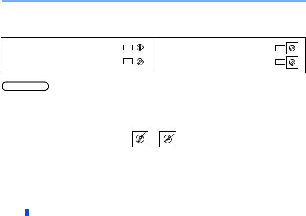
Even if the option is inserted to the option connector 1, when the inverter cannot recognize that the option is mounted due to improper installation, etc., the protective function (E.1) is activated.
Mounted position |
Fault indication |
|
|
|
2 |
||||
Option connector 1 |
|
|
||
|
|
|
|
Option connector 2
Option connector 3
•When removing the plug-in option, remove the two screws on the left and right, then pull it straight out. Pressure applied to the connector and to the option board may break the option.
•Always attach the earth plate because a malfunction due to noises may occur without it.
INSTALLATION |
|
17 |
|
2.3Node address setting
Set the node address between "1 to 64" using node address switches on the FR-A8NF (refer to page 8). The setting is applied at the next power-on.
Set the arrow ( ) of the corresponding switches to the number to set a desired node address.
• Setting example
Node address 1:
Set the arrow () of X10 (SW2) to "0" and the arrow X10 () of X1 (SW1) to "1".
X1
9 |
0 |
1 |
8 |
|
2 |
7 |
|
3 |
6 |
5 |
4 |
|
|
|
9 |
0 |
1 |
8 |
|
2 |
7 |
|
3 |
6 |
5 |
4 |
Node address 26:
Set the arrow () of X10 (SW2) to "2" and the arrow X10 () of X1 (SW1) to "6".
X1
9 |
0 |
1 |
8 |
|
2 |
7 |
|
3 |
6 |
5 |
4 |
|
|
|
9 |
0 |
1 |
8 |
|
2 |
7 |
|
3 |
6 |
5 |
4 |
|
|
 NOTE
NOTE
•Set the inverter node address before switching ON the inverter and do not change the setting while power is ON. Otherwise you may get an electric shock.
•Set the node address switches so that the arrow points the exact position. If the switch is set between numbers, normal data communication can not be established.
Good Bad example example
9 8
7 6
0
5
1 2
3 4
9 8
7 6
0
5
1 2
3 4
•If the node address switch is set to a value other than "1 to 64", it is invalid due to outside of setting range. In this case, DEV LED of the option is lit red and E.OPT appears on the operation panel of the inverter.
•You cannot set the same node address to other devices on the network. (Doing so disables proper communication.)
•Changes in the node address setting are applied only at the next power-ON. Therefore, if the node address setting is changed, make sure to power OFF and ON the inverter power.
18 INSTALLATION

3 WIRING
3.1Connection to network
(1)Be sure to check the following before connecting the inverter to the network.
•Check that the FR-A8NF is correctly mounted to the inverter. (Refer to page 15.)
•Check that the correct node address is set. (Refer to page 18.)
•Check that the FL-net dedicated cable is correctly connected to the FR-A8NF. (Refer to page 21.)
(2)System configuration
Segment 1 |
Personal computer |
Master |
3 |
|
Segment 2 |
Hub |
Hub |
|
Cascade connection (100m maximum) |
|
||
(100m maximum) |
|
|
|
|
Inverter |
Inverter |
Inverter |
Inverter |
Inverter |
Overall length: 2000m maximum |
|
|
||
WIRING |
|
19 |
|
3.2Connection cable specifications
Connect the FR-A8NF to the FL remote network using the FL-net dedicated cable below.
Item |
Description |
|
|
TPCC5 or more (Twisted Pair Communication Cable for LAN Category 5) |
|
Cables |
For the shape, use STP (Shielded Twisted Pair) |
|
|
(according to the 100BASE-TX (IEEE802.3u) standard) |
|
|
|
|
Maximum wiring length |
100 m maximum between hub and inverter. |
|
(according to the 100BASE-TX (IEEE802.3u) standard) |
||
|
||
|
|
• Designated product (as of February 2015)
Type |
Cable Length (m) |
Maker |
FLG-S-[] |
1 to 100 m |
Shinwa Co., Ltd. |
|
|
|
The cable length is indicated in the brackets (FLG-S-010 for 1 m length, FLG-S-1000 for 100 m length).
3.3Precautions for system configuration
Enough safety measures are necessary when installing the FL-net dedicated cable and connecting to the FL remote network. Consult the network provider and network administrator (person in charge of network planning and IP address management) including terminal treatment of connection cable, construction of trunk cable, etc.
We are not responsible for system troubles from connecting to the FL remote network.
20 WIRING

3.4Wiring
This section explains connection of the FL-net dedicated cable and the relevant precautions.
For the details of the network configuration and the cables used for wiring, refer to page 19 and 20.
3.4.1Connecting the FL-net dedicated cable
Connecting the cable
(1)Turn OFF the inverter power supply.
(2)Remove the front cover.
(3)Check the orientation of the connectors. Insert the connector part of the FL-net dedicated cable to the communication connector of the FR-A8NF until it clicks.
Disconnecting the cable
(1)Turn OFF the inverter power supply.
(2)Remove the front cover.
(3)Pull out the FL-net dedicated cable while holding the release tab of the connector part.
Communication connector of the FR-A8NF
3
FL-net dedicated cable
 Caution
Do not connect the parameter unit (FR-PU07, etc.) to the FR-A8NF communication connector. Doing so will damage the option.
After wiring, wire offcuts must not be left in the inverter. Wire offcuts can cause an alarm, failure or malfunction.
WIRING |
|
21 |
|

4 INVERTER SETTING
4.1Parameter list
Parameters related to the communication option (FR-A8NF)
|
Pr. |
|
|
Setting |
|
Minimum |
Initial |
Refer to |
Pr. |
Name |
|
|
setting |
||||
group |
|
range |
|
value |
page |
|||
|
|
|
|
increments |
||||
|
|
|
|
|
|
|
|
|
501 |
N012 |
Communication error occurrence count display |
0 |
|
1 |
|
0 |
32 |
|
|
|
|
|
|
|
|
|
Available when the plug-in option (FR-A8NF) is connected.
22 INVERTER SETTING
Parameters whose functions are always the same
When the FR-A8NF is installed to the inverter, each function of some parameters is fixed as follows. (Changed setting is invalid even if the setting value is changed.)
Pr. |
Pr. |
Name |
Setting |
|
Refer |
|
|
group |
(fixed) |
Function |
to page |
|
|
||
|
|
|
|
||||
76 |
M510 |
Fault code output selection |
0 |
Without fault code output |
|
|
|
|
|
|
|
|
|
|
|
79 |
D000 |
Operation mode selection |
7 |
PU operation interlock |
26 |
|
|
|
|
|
|
|
|
|
|
180 |
T702 |
RL terminal function |
0 |
Low-speed operation command |
|
|
|
selection |
|
|
|||||
|
|
|
|
|
|
|
|
|
|
|
|
|
|
|
|
181 |
T703 |
RM terminal function |
1 |
Middle-speed operation command |
|
|
|
selection |
|
|
|||||
|
|
|
|
|
|
|
|
182 |
T704 |
RH terminal function |
2 |
High-speed operation command |
|
|
|
selection |
|
|
|||||
|
|
|
|
|
|
|
|
|
|
|
|
|
|
|
|
183 |
T705 |
RT terminal function |
3 |
Second function selection |
|
|
|
selection |
|
4 |
|||||
|
|
|
|
|
|
||
|
|
|
|
|
|
|
|
184 |
T706 |
AU terminal function |
9999 |
- (no function) |
|
|
|
|
|
selection |
|
|
|
|
|
|
|
|
|
|
|
|
|
185 |
T707 |
JOG terminal function |
9999 |
- (no function) |
|
|
|
selection |
|
|
|||||
|
|
|
|
|
|
|
|
|
|
|
|
|
|
|
|
186 |
T708 |
CS terminal function |
9999 |
- (no function) |
|
|
|
selection |
|
|
|||||
|
|
|
|
|
|
|
|
|
|
|
|
|
|
|
|
187 |
T709 |
MRS terminal function |
24 |
Output stop |
|
|
|
selection |
|
|
|||||
|
|
|
|
|
|
|
|
188 |
T710 |
STOP terminal function |
9999 |
- (no function) |
|
|
|
selection |
|
|
|||||
|
|
|
|
|
|
|
|
|
|
|
|
|
|
|
|
189 |
T711 |
RES terminal function |
12 |
PU operation interlock |
|
|
|
selection |
|
|
|||||
|
|
|
|
|
|
|
|
|
|
|
|
|
|
|
|
INVERTER SETTING |
|
23 |
|
Pr. |
Pr. |
Name |
|
Setting |
|
Refer |
|
group |
|
(fixed) |
Function |
to page |
|||
|
|
|
|||||
190 |
M400 |
RUN terminal function |
0 |
|
|
Inverter running |
|
selection |
|
|
|||||
|
|
|
|
|
|
|
|
191 |
M401 |
SU terminal function |
1 |
|
|
Up to frequency |
|
selection |
|
|
|||||
|
|
|
|
|
|
|
|
|
|
|
|
|
|
|
|
192 |
M402 |
IPF terminal function |
2 |
|
9999 |
Instantaneous power failure/undervoltage |
|
selection |
|
||||||
|
|
|
|
|
|
|
|
|
|
|
|
|
|
|
|
193 |
M403 |
OL terminal function |
3 |
|
|
Overload alarm |
|
selection |
|
|
|||||
|
|
|
|
|
|
|
|
194 |
M404 |
FU terminal function |
4 |
|
|
Output frequency detection |
|
selection |
|
|
|||||
|
|
|
|
|
|
|
|
|
|
|
|
|
|
|
|
195 |
M405 |
ABC1 terminal function |
99 |
|
|
Fault output |
|
selection |
|
|
|||||
|
|
|
|
|
|
|
|
|
|
|
|
|
|
|
|
196 |
M406 |
ABC2 terminal function |
9999 |
|
|
- (no function) |
|
selection |
|
|
|||||
|
|
|
|
|
|
|
|
338 |
D010 |
Communication operation |
0 |
|
|
Operation command source communication |
30 |
command source |
|
|
|||||
|
|
|
|
|
|
|
|
|
|
|
|
|
|
|
|
339 |
D011 |
Communication speed |
0 |
|
|
Frequency command source communication |
30 |
command source |
|
|
|||||
|
|
|
|
|
|
|
|
|
|
|
|
|
|
|
|
|
|
Communication startup |
|
|
|
Started in the Network operation mode. Operation mode |
|
340 |
D001 |
10 |
|
|
can be changed between the PU operation mode and |
26 |
|
mode selection |
|
|
|||||
|
|
|
|
|
Network operation mode from the operation panel. |
|
|
|
|
|
|
|
|
|
|
|
|
|
|
|
|
|
|
342 |
N001 |
Communication EEPROM |
0 |
|
|
Parameter values written by communication are written |
|
|
|
write selection |
|
|
|
to the EEPROM and RAM. |
|
|
|
Communication error |
|
|
|
There is no waiting time (0 s) since the communication |
|
500 |
N011 |
0 |
|
|
line fault occurrence until communication error. Note |
|
|
execution waiting time |
|
|
that actual time depends on the detection time on the |
||||
|
|
|
|
|
|
FL remote network. |
|
|
|
|
|
|
|
|
|
24 |
|
INVERTER SETTING |
|

Pr. |
Pr. |
Name |
Setting |
|
Refer |
|
group |
(fixed) |
Function |
to page |
|||
|
|
|||||
502 |
N013 |
Stop mode selection at |
1 |
The inverter decelerates to stop at communication fault |
33 |
|
communication error |
occurrence, when provide a fault output. |
|||||
|
|
NET mode operation |
|
Automatic communication option recognition |
|
|
550 |
D012 |
9999 |
Normally, control source of the RS-485 terminal is valid. |
|
||
|
|
command source selection |
|
When a communication option is mounted, the control |
|
|
|
|
|
|
source of the communication option is valid. |
|
|
|
|
|
|
|
|
|
551 |
D013 |
PU mode operation |
2 |
Selects the PU connector as the PU operation mode |
|
|
command source selection |
operation source. |
|||||
|
|
|
|
Available when the plug-in option (FR-A8NF) is connected.Refer to the Instruction Manual (Detailed) of the inverter.For the standard model and the IP55 compatible model.For the separated converter type.
For the separated converter type, the setting (fixed) remains "24". However, the X10 signal (Inverter run enable signal (FR-HC2/FR-CV/ FR-CC2 connection)) operation is performed.
When the FR-A8TP is installed to the separated converter type, the setting (fixed) remains "9999". However, the X10 signal operation is performed.
NOTE
4
•Functions that use terminal AU, JOG, CS, or STOP are not available. Also, signals not listed in the table cannot be assigned to the I/O terminals.
INVERTER SETTING |
|
25 |
|

4.2Operation mode setting
Powering ON the inverter with the communication option (FR-A8NF) installed starts the inverter in the Network operation mode. (The operation mode cannot be changed to the External operation mode when the FR-A8NF is installed.)
Operation mode switching conditions
Check the following before switching the operation mode.
• The inverter is at a stop.
• Both the STF and STR signals are turned OFF.
Operation mode switchover method
Power-ON |
|
|
1 |
|
|
C |
External operation |
A |
Network operation |
PU operation |
|
D |
|
B |
E
F
When powered ON with the FR-A8NF installed, the inverter starts in the Network operation mode.
26 INVERTER SETTING

Symbol |
Operation mode switchover |
|
|
Switchover method |
|
|
||
|
|
The operation mode can not be switched in power-ON status. After powering OFF |
|
|
||||
A |
External operation →PU operation |
the inverter, remove the FR-A8NF and power ON the inverter again. Then, press the |
|
|
||||
|
|
key on the operation panel. |
|
|
|
|||
|
|
|
|
|
|
|
||
|
|
|
|
|
|
|
||
|
|
|
|
|
|
|
|
|
B |
PU operation →External operation |
The operation mode can not be switched in power-ON status. After powering OFF the |
|
|
||||
|
|
|
|
|||||
C |
Network operation →External operation |
inverter, remove the FR-A8NF and power ON the inverter again. |
|
|
||||
|
|
|
|
|
|
|
||
|
|
|
|
|
|
|
|
|
|
|
The operation mode can not be switched in power-ON status. After powering OFF the |
|
|
||||
D |
External operation →Network operation |
inverter, install the FR-A8NF to the option connector 1 and power ON the inverter |
|
|
||||
|
|
again. |
|
|
|
|||
|
|
|
|
|
|
|
|
|
|
|
Turn ON the X12 signal (Bit 11) which enables operation command through the FL |
|
|
||||
E |
Network operation →PU operation |
remote communication, and press the |
|
key on the operation panel. (Refer to |
|
|
||
|
|
|
||||||
|
|
page 28.) |
|
|
|
|||
|
|
|
|
|
|
|
|
|
F |
PU operation →Network operation |
Turn OFF the X12 signal (Bit 11), which gives operation commands through the FL |
|
4 |
||||
remote communication. (Refer to page 28.) |
|
|
||||||
|
|
|
||||||
|
|
|
|
|
||||
|
|
|
|
|
|
|
|
|
|
|
|
|
|
|
|
|
|
INVERTER SETTING |
|
27 |
|

Operation mode switching by the PU operation interlock signal (X12)
PU operation interlock is a function that forcefully changes the operation mode to the Network operation mode at turn-OFF of the X12 signal (Bit 11), which gives operation commands through the FL remote communication.
This function prevents the operation mode from being accidentally unswitched from the PU operation mode. If the operation mode left unswithced from the PU operation mode, the inverter does not reply to the commands sent through the FL remote communication.
X12 |
|
Function/operation |
|
signal |
Operation mode |
|
Parameter write |
ON |
Operation mode (PU, NET) switching is enabled. |
|
Parameter write is enabled. (It depends on Pr.77 Parameter write |
|
selection and each parameter write conditions. Refer to the Instruction |
||
Output stops during the Network operation. |
|
||
|
|
Manual (Detailed) of the inverter.) |
|
|
|
|
|
|
|
|
|
|
Operation mode is forcibly switched to the Network. |
|
Parameter write is disabled. |
OFF |
Network operation is enabled. |
|
|
|
(Note that the Pr.297 setting is available when Pr.296 ≠ "9999.") |
||
|
Switching to the PU operation mode is disabled. |
|
|
|
|
|
|
|
|
|
|
28 INVERTER SETTING

• Function/operation changed by switching ON-OFF the X12 signal
Operating condition |
|
Operation |
|
Switching to PU |
||
Operation |
|
X12 signal |
Operating status |
|||
Status |
mode |
operation mode |
||||
|
|
|||||
mode |
|
|
|
|
|
|
PU |
During stop |
ON→OFF |
|
If Network operation frequency setting and start |
Disallowed |
|
|
|
|
signal are entered, operation is performed in that |
|
||
Running |
ON→OFF |
|
Disallowed |
|||
|
|
status. |
||||
|
|
|
|
|
|
|
|
During stop |
OFF→ON |
Network |
During stop |
Allowed |
|
|
|
|
||||
Network |
ON→OFF |
Disallowed |
||||
|
|
|
||||
|
|
|
|
|
||
Running |
OFF→ON |
|
During operation → output stop |
Disallowed |
||
|
|
|||||
|
|
|
|
|
||
|
ON→OFF |
|
Output stop → operation |
Disallowed |
||
|
|
|
||||
|
|
|
|
|
|
|
The operation mode switches to the Network operation mode independently of whether the start signal (STF, STR) is ON or OFF. Therefore, the motor is run in the Network operation mode when the X12 signal is turned OFF with either of STF and STR ON.
At fault occurrence, pressing |
of the operation panel resets the inverter. |
4 |
|
NOTE
•If the X12 signal is ON, the operation mode cannot be switched to the PU operation mode when the start signal (STF, STR) is ON.
•The X12 signal is valid only when it is input via the FL remote communication. (The X12 signal is invalid when it is input from a control circuit terminal of the inverter.)
•When the FR-A8NF is installed, Pr.79 Operation mode selection and Pr.340 Communication startup mode selection settings are invalid.
INVERTER SETTING |
|
29 |
|
Loading...