


 Loading...
INVERTER
FR-D700
Safety stop function instruction manual
|
CONTENTS |
|
1. |
General description ............................................................................ |
1 |
2. |
Installation and wiring ........................................................................ |
2 |
3. |
Example of safety system configuration........................................... |
5 |
4. |
Test and checking failure ................................................................... |
9 |
5. |
Safety parameters of FR-D700 ......................................................... |
10 |
Compliance with the EU Machinery Directive – Functional Safety
WARNING
Any misuse of safety function could lead to personal injury or death, property damage, or economic loss. To ensure that the system complies fully with requirement of safety, make a system-level risk assessment. Mitsubishi Electric Co. cannot assume responsibility for any system to comply with safety directive.
CAUTION
The information of this manual is merely a guide for proper installation.
Mitsubishi Electric Co. cannot assume responsibility for the compliance or the noncompliance to any code, national, local or otherwise for the proper installation of this equipment.
A hazard of personal injury and/or equipment damage exists if codes are ignored during installation.
WARNING
To avoid an electric shock hazard, verify that the voltage on the bus capacitors has discharged before performing any work on the drive. Measure the DC bus voltage at the P(+) and N(-) terminals or test points (refer to your drive’s User Manual for locations and discharging time). The voltage must be zero.
WARNING
The safety stop function do not isolate electrically between drive and motor. To avoid an electric shock hazard, disconnect/isolate power to the drive and verify to ensure that the voltage is zero before performing any work on the motor (refer to your drive’s User Manual for discharging time).
CAUTION
If you are using a FR-D740-EC with serial number shown below, safety function does not work according to safety standard. In such case please contact your sales person.
<Europe model : suffixed with ‘-EC’>
D740-012 to 080–EC : Axxxxx, Bxxxxx, Cxxxxx, Dxxxxx, Exxxx and Fxxxxx D740-120 to 160–EC : Axxxxx, Bxxxxx, Cxxxxx and Dxxxxx
Check the SERIAL number indicated on the inverter rating plate or package.
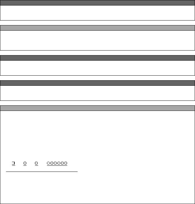
Rating plate example
Symbol Year Month Control number
SERIAL (Serial No.)
The SERIAL consists of 1 version symbol, 2 numeric characters or 1 numeric character and 1 alphabet letter indicating year and month, and 6 numeric characters indicating control number.
Last digit of the production year is indicated as the Year, and the Month is indicated by 1 to 9, X (October), Y (November), and Z (December).

1. General description
Features
Mitsubishi FR-D700 safety stop function prevents a drive from supplying rotational energy to motors. Dual safety channels ‘S1’ and ‘S2’ cut off the gate-drive power for IGBT to turn off.
Input power
|
|
+24V |
FR-D700 |
|
|
|
|
|
|
|
|
|
S2 |
|
|
|
|
|
|
+24V |
|
|
|
|
S1 |
|
|
|
|
Internal |
|
|
G |
G |
IGBTs |
Safety |
|
|
|
|
|
|
|
|
|
|
|
Circuit |
|
|
Gate |
Gate |
|
|
|
|
|
|
|
|
SC |
CPU |
Driver |
Driver |
|
Safety relay module |
|
|
|
||
|
|
|
|
|
|
|
|
|
|
|
M |
Fig.1 FR-D700 safety stop function diagram
WARNING
The safety stop function doesn’t isolate electrically between drive and motor. To avoid an electric shock hazard, disconnect power to the drive and verify that the voltage is zero before performing any work on the motor (refer to your drive’s User Manual for discharging time).
Directives
Mitsubishi FR-D700 safety stop function meets the following directives and categories. ISO13849-1:2008 Category 3/PLd (applies to the FR-D700 manufactured in January 2012 or later) IEC62061:2005 / IEC61800-5-2:2007 / IEC61508 SIL2
IEC60204-1:2006 / IEC61800-5-2:2007 Stop category 0
WARNING
The misuse of safety function leads to personal injury or death, property damage, or economic loss.
To ensure that the system complies fully with requirement of safety, make a system-level risk assessment. Mitsubishi Electric Co. cannot assume responsibility for any system to comply with safety directive.
1

2. Installation and wiring
CAUTION
The following information is merely a guide for proper installation.
Mitsubishi Electric Co. cannot assume responsibility for the compliance or the noncompliance to any code, national, local or otherwise for the proper installation of this equipment.
A hazard of personal injury and/or equipment damage exists if codes are ignored during installation.
CAUTION
Ensure the safety relay unit and the FR-D700 unit is mounted closely in enclosure meeting IP54 and all interconnection wiring is short and protected against open and short circuit faults.
Refer EN/ISO13849-2.
Installation
Mitsubishi FR-D700 safety stop function should be used under following condition and environment.
Table.1 The condition and environment for using safety stop function
Item |
|
Condition |
|
Temperature |
|
Operation |
-10°C to +50°C (non-freezing) |
range |
|
Storage |
-20°C to +65°C |
Ambient humidity |
|
90%RH maximum (non-condensing) |
|
Vibration |
|
5.9m/s2 or less |
|
Altitude |
|
maximum 1000m above sea level |
|
Atmosphere |
|
Indoors (without corrosive gas, flammable gas, oil mist, dust and dirt etc.) |
|
Over voltage category |
II or less |
||
Pollution degree |
|
II or less |
|
Mounting |
|
wall mounting / vertical orientation |
|
CAUTION
In order to meet safety stop, an approved safety relay unit to ISO13849-1/EN954-1 safety category 3 or better shall be used in conjunction with FR-D700 as shown in example1,2.
In addition, all other components with in the safety stop loop shall be ‘safety approved’ types.
WARNING
To avoid an electric shock hazard, insert the magnetic contactor (MC) between power source and drive. Open the contact of MC and keep away from drive for discharging time (refer to your drive’s User Manual for information) before performing any work on the drive.
And verify that the voltage on the bus capacitors has discharged before Measure the DC bus voltage at the P(+) and N(-) terminals or test points (refer to your drive’s User Manual for locations). The voltage must be zero.
CAUTION
To avoid systematic faults, a test even for faulty demands of the safety function has to be performed in order to check the correct function of the monitor signal. This test shall be carried out at system installation, any software changes, parameterization changes, and/or at least once per year.
Refer to ‘4. Test and checking failure’.
2

Wiring
The safety related terminals are described in Table.2 and Table.3
|
|
Table.2 The safety related terminals |
|
|
|
|
|
|
|
|
|
|
|
Terminal |
|
Description |
|
|
Rating |
|
Symbol |
|
|
|
|
||
|
|
|
|
|
|
|
|
|
For input of safety stop channel1. |
|
Input resistance:4.7kΩ |
||
S1 |
|
S1-SC is |
|
Current : 4 to 6 mA |
||
|
Open: In safety stop mode. |
|
(In case of shorted to SC) |
|||
|
|
|
||||
|
|
Short: Non safety stop mode. |
|
Voltage : 21 to 26 V |
||
|
|
For input of safety stop channel2. |
|
(In case of open from SC) |
||
S2 |
|
S2-SC is |
|
|
|
|
|
Open: In safety stop mode. |
|
|
|
||
|
|
|
|
|
||
|
|
Short: Non safety stop mode. |
|
|
|
|
|
|
As output for safety stop condition. |
|
Load: 24VDC/0.1A max. |
||
|
|
SO terminal type is ‘Open collector output’. |
|
Voltage drop: 3.4V max. |
||
SO |
|
SO-SC is |
|
(In case of ‘ON’ state) |
||
|
OFF(Open): Drive enabled, or drive shutoff (with |
|
|
|
||
(SAFE) |
|
internal circuit fault) |
|
|
|
|
|
|
ON(Close): Drive shutoff (no internal circuit fault) |
|
|
|
|
|
|
Important: SO terminal should be used for monitoring safety stop |
|
|
|
|
|
|
condition only. SO terminal cannot be used for safety function. |
|
|
|
|
SC |
|
Common terminal for S1, S2, SO terminals. |
|
|
|
|
|
*SC is connected terminal SD internally. |
|
|
|
||
|
|
|
|
|
||
|
|
As output for failure detection and alarm. RUN terminal type is ‘Open |
|
Load: 24VDC/0.1A max. |
||
|
|
collector output’. |
|
Voltage drop: 3.4V max. |
||
|
|
RUN-SE is |
|
(In case of ‘ON’ state) |
||
|
|
OFF(Open): Detect failure or Alarm. |
|
|
|
|
RUN |
|
ON(Close): No failure detected. |
|
|
|
|
|
|
|
|
|
|
|
(SAFE2) |
|
Attention: To use RUN terminal for monitor output of failure |
|
|
|
|
|
|
detection, The parameter No.190 should be set 81 |
|
|
|
|
|
|
(Safety monitor 2). |
|
|
|
|
|
|
Note: This terminal can be used for alarm or to prevent restart only, |
|
|
|
|
|
|
no other safety function. |
|
|
|
|
SE |
|
Common terminal for safety RUN terminal. |
|
|
|
|
|
|
As output for failure detection. A,C terminal type is ‘Relay output’. |
|
Load: 30VDC/0.3A max. |
||
|
|
A-C is |
|
|
|
|
|
|
OFF(Open): Detect failure or Alarm. |
|
|
|
|
A,C |
|
ON(Close): No failure detected. |
|
|
|
|
|
|
|
|
|
|
|
(SAFE2) |
|
Attention: To use A,C terminal for monitor output of failure |
|
|
|
|
|
|
detection, The parameter No.192 should be set 81 |
|
|
|
|
|
|
(Safety monitor 2). |
|
|
|
|
|
|
Note: This terminal can be used for alarm or to prevent restart only, |
|
|
|
|
|
|
no other safety function. |
|
|
|
|
SD |
|
Signal ground |
|
|
|
|
3
Loading...