


 MITSUBISHI ELECTRIC
FR-F700
Inverter
Instruction Manual
FR-F740 EC
FR-F746 EC
Art. no.: 166461 |
|
|
|
13 06 2013 |
MITSUBISHI ELECTRIC INDUSTRIAL AUTOMATION |
||
|
|||
Version F |
|
|
Version check |

|
|
|
|
Instruction Manual |
|
|
|
|
Inverter FR-F700 EC |
|
|
|
|
Art. no.: 166461 |
|
|
|
|
|
|
Version |
|
|
Changes / Additions / Corrections |
A |
04/2005 |
pdp |
First Edition |
|
|
|
|
|
|
B |
07/2005 |
pdp |
Section 3.8.1 |
Revision of the section "Note on selecting a suitable power |
|
|
|
|
supply ELCB" |
|
|
|
|
|
C |
03/2006 |
pdp |
General |
Extension of the capacity classes by the inverters |
|
|
|
|
FR-F740-02600 to 12120 |
|
|
|
|
Addition of the inverters FR-F746-00023 to 01160 with |
|
|
|
|
IP54 protection rating |
|
|
|
|
New parameter 299 |
|
|
|
Section 2.4.3 |
Addition of a heatsink protrusion attachment |
|
|
|
|
|
D |
08/2010 |
akl |
General |
Adaption of document version numbers (english, german) |
|
|
|
|
|
E |
10/2010 |
akl |
General |
Additions: |
|
|
|
|
• Voltage/current input switch |
|
|
|
Section 7.2 |
• Additional explanation to "Causes and corrective actions" |
|
|
|
General |
• DC feeding operation permission signal (X70), DC feeding |
|
|
|
|
cancel signal (X71), PID integral value reset signal (X72) |
|
|
|
|
• PID deviation limit signal (Y48), Pulse output of output power |
|
|
|
|
signal (Y79), DC feeding signal (Y85) |
New setting values:
•Pr. 29 "Acceleration/deceleration pattern selection" setting value "6"
•Pr. 30 "Regenerative function selection" setting values "10", "11", "20", "21"
•Pr. 59 "Remote function selection" setting values "11", "12", "13"
•Pr. 128 "PID action selection" setting values "110", "111", "120", "121"
•Pr. 167 "Output current detection operation selection" setting values "10", "11"
•Pr. 261 "Power failure stop selection" setting values "21", "22"
•Pr. 495 "Remote output selection" setting values "10", "11"
New parameters:
•Pr. 522 "Output stop frequency"
•Pr. 539 "Modbus-RTU communication check time interval"
•Pr. 653 "Speed smoothing control"
•Pr. 654 "Speed smoothing cutoff frequency"
•Pr. 553 "PID deviation limit", Pr. 554 "PID signal operation selection", C42 (Pr. 934) "PID display bias coefficient",
C43 (Pr. 934) "PID display bias analog value", C44 (Pr. 935) "PID display gain coefficient", C45 (Pr. 935) "PID display gain analog value"
•Pr. 799 "Pulse increment setting for output power"
Partial changes
• Pr. 153 "Zero current detection time" setting range "0 to 10s" Section 7.6 • Check first when you have a trouble

|
|
|
Instruction Manual |
|
|
|
Inverter FR-F700 EC |
|
|
|
Art. no.: 166461 |
|
|
|
|
|
Version |
|
Changes / Additions / Corrections |
F |
06/2013 |
akl General |
New parameters: |
|
|
|
• Pr. 147, Pr. 296, Pr. 297, Pr. 390, Pr. 414, Pr. 415, Pr. 498, |
|
|
|
Pr. 502, Pr. 505 to Pr. 515, Pr. 561, Pr. 665, Pr. 726 to Pr. 729, |
|
|
|
Pr. 753 to Pr. 769, Pr. 774 to Pr. 779, Pr. 826 to Pr. 865, Pr. 870, |
|
|
|
Pr. 986, Pr. 997, Pr. 999 |
New setting values:
•Pr. 30, Pr. 52, Pr. 54, Pr. 128, Pr. 158, Pr. 178 to Pr. 189, Pr. 190 to Pr. 196, Pr. 331, Pr. 332, Pr. 549, Pr. 573
Additions:
•Option connector 2
•Easy operation mode setting
•Function enhancement of Mitsubishi inverter protocol/ Modbus-RTU protocol communication
•BACnet MS/TP protocol
•PLC function
•Initial value change list
•Protective functions (LOCD, E.2, E.OP2, E.PCH, E.LCI)
•Dimensions of DC reactors FFR-HEL-H-E

Thank you for choosing this Mitsubishi inverter.
This instruction manual provides instructions for advanced use of the FR-F700 series inverters. Incorrect handling might cause an unexpected fault. Before using the inverter, always read this instruction manual to use the equipment to its optimum.
Safety instructions
Do not attempt to install, operate, maintain or inspect the inverter until you have read through this instruction manual carefully and can use the equipment correctly. Do not use the inverter until you have a full knowledge of the equipment, safety information and instructions. In this instruction manual, the safety instruction levels are classified into "WARNING" and "CAUTION".
WARNING:
P Assumes that incorrect handling may cause hazardous conditions, resulting in death or severe injury.
CAUTION:
E Assumes that incorrect handling may cause hazardous conditions, resulting in medium or slight injury, or may cause physical damage only.
Note that even the CAUTION level may lead to a serious consequence according to conditions. Please follow strictly the instructions of both levels because they are important to personnel safety.
FR-F700 EC |
I |

Electric shock prevention
WARNING:
P ● While power is on or when the inverter is running, do not open the front cover.
Otherwise you may get an electric shock.
●Do not run the inverter with the front cover removed. Otherwise, you may access the exposed high-voltage terminals or the charging part of the circuitry and get an electric shock.
●Even if power is off, do not remove the front cover except for wiring or periodic inspection. You may access the charged inverter circuits and get an electric shock.
●Before starting wiring or inspection, check to make sure that the operation panel indicator is off, wait for at least 10 minutes after the power supply has been switched off, and check that there are no residual voltage using a tester or the like. The capacitor is charged with high voltage for some time after power off and it is dangerous.
●This inverter must be earthed. Earthing must conform to the requirements of national and local safety regulations and electrical codes. (JIS, NEC section 250, IEC 536 class 1 and other applicable standards)
●Any person who is involved in the wiring or inspection of this equipment should be fully competent to do the work.
●Always install the inverter before wiring. Otherwise, you may get an electric shock or be injured.
●If your application requires by installation standards an RCD (residual current device) as up stream protection please select according to DIN VDE 0100-530 as following:
Single phase inverter type A or B Three phase inverter only type B.
●Perform setting dial and key operations with dry hands to prevent an electric shock. Otherwise you may get an electric shock. Perform setting dial and key operations with dry hands to prevent an electric shock. Otherwise you may get an electric shock.
●Do not subject the cables to scratches, excessive stress, heavy loads or pinching. Otherwise you may get an electric shock.
●Do not replace the cooling fan while power is on. It is dangerous to replace the cooling fan while power is on.
●Do not touch the printed circuit board or handle the cables with wet hands. You may get an electric shock.
II |
MITSUBISHI ELECTRIC |

Fire prevention
CAUTION:
E ● Install the inverter on a nonflammable wall without holes (so that nobody can touch the inverter heatsink on the rear side, etc.). Mounting it to or near combustible material can cause a fire.
●If the inverter has become faulty, switch off the inverter power. A continuous flow of large current could cause a fire.
●Do not connect a resistor directly to the DC terminals P/+, N/–. This could cause a fire and destroy the inverter. The surface temperature of braking resistors can far exceed 100°C for brief periods. Make sure that there is adequate protection against accidental contact and a safe distance is maintained to other units and system parts.
Injury prevention
CAUTION:
E ● Apply only the voltage specified in the instruction manual to each terminal. Otherwise, burst, damage, etc. may occur.
●Ensure that the cables are connected to the correct terminals. Otherwise, burst, damage, etc. may occur.
●Always make sure that polarity is correct to prevent damage, etc. Otherwise, burst, damage, etc. may occur.
●While power is on or for some time after power-off, do not touch the inverter as it is hot and you may get burnt.
FR-F700 EC |
III |

Additional instructions
Also note the following points to prevent an accidental failure, injury, electric shock, etc.
Transportation and installation
E |
CAUTION: |
|
|
● When carrying products, use correct lifting gear to prevent injury. |
|||
|
● Do not stack the inverter boxes higher than the number recommended. |
||
|
● Ensure that installation position and material can withstand the weight of the |
||
|
inverter. Install according to the information in the instruction manual. |
||
|
● Do not install or operate the inverter if it is damaged or has parts missing. This can |
||
|
result in breakdowns. |
|
|
|
● When carrying the inverter, do not hold it by the front cover or setting dial; it may |
||
|
fall off or fail. |
|
|
|
● Do not stand or rest heavy objects on the product. |
|
|
|
● Check the inverter mounting orientation is correct. |
|
|
|
● Prevent other conductive bodies such as screws and metal fragments or other |
||
|
flammable substance such as oil from entering the inverter. |
||
|
● As the inverter is a precision instrument, do not drop or subject it to impact. |
||
|
● Use the inverter under the following environmental conditions. Otherwise, the |
||
|
inverter may be damaged |
|
|
|
|
|
|
|
|
|
|
|
Operating Condition |
FR-F740 |
FR-F746 |
|
|
|
|
|
Ambient temperature |
−10°C to +40/+50°C (non-freezing) |
−10°C to +30/+40°C (non-freezing) |
|
|
|
|
|
The maximum temperature depends on the setting of Pr. 570. |
||
|
|
||
|
|
|
|
|
Ambient humidity |
90% RH or less (non-condensing) |
|
|
|
|
|
|
Storage temperature |
−20°C to +65°C |
|
|
Atmosphere |
Indoors (free from corrosive gas, flammable gas, oil mist, dust and dirt) |
|
|
|
|
|
|
Altitude |
Maximum 1000m above sea level for standard operation. After that derate by 3% for |
|
|
every extra 500m up to 2500m (91%) |
|
|
|
|
|
|
|
|
|
|
|
Vibration |
5.9m² or less at 10 to 55Hz (directions of X, Y, Z axes) |
|
Temperature applicable for a short time, e.g. in transit.
2.9m/s² or less for the 04320 or more.
Wiring
CAUTION:
E ● Do not install assemblies or components (e. g. power factor correction capacitors) on the inverter output side, which are not approved from Mitsubishi.
●The direction of rotation of the motor corresponds to the direction of rotation commands (STF/STR) only if the phase sequence (U, V, W) is maintained.
IV |
MITSUBISHI ELECTRIC |

Operation
WARNING:
P ● When you have chosen the retry function, stay away from the equipment as it will restart suddenly after an alarm stop.
●Since pressing STOP/RESET key may not stop output depending on the function setting status, provide a circuit and switch separately to make an emergency stop (power off, mechanical brake operation for emergency stop, etc.).
●Make sure that the start signal is off before resetting the inverter alarm. A failure to do so may restart the motor suddenly.
●The inverter can be started and stopped via the serial port communications link or the field bus. However, please note that depending on the settings of the communications parameters it may not be possible to stop the system via these connections if there is an error in the communications system or the data line. In configurations like this it is thus essential to install additional safety hardware that makes it possible to stop the system in an emergency (e.g. controller inhibit via control signal, external motor contactor etc). Clear and unambiguous warnings about this must be posted on site for the operating and service staff.
●The load used should be a three-phase induction motor only. Connection of any other electrical equipment to the inverter output may damage the inverter as well as the equipment.
●Do not modify the equipment.
●Do not perform parts removal which is not instructed in this manual. Doing so may lead to fault or damage of the inverter.
FR-F700 EC |
V |

CAUTION:
E ● The electronic thermal relay function does not guarantee protection of the motor from overheating. It is recommended to install both an external thermal and PTC thermistor for overheat protection.
●Do not use a magnetic contactor on the inverter input for frequent starting/stopping of the inverter. Otherwise, the life of the inverter decreases.
●Use a noise filter to reduce the effect of electromagnetic interference and follow the accepted EMC procedures for proper installation of frequency inverters. Otherwise nearby electronic equipment may be affected.
●Take appropriate measures regarding harmonics. Otherwise this can endanger compensation systems or overload generators.
●Use a motor designed for inverter operation. (The stress for motor windings is bigger than in line power supply).
●When parameter clear or all clear is performed, set again the required parameters before starting operations. Each parameter returns to the initial value.
●The inverter can be easily set for high-speed operation. Before changing its setting, fully examine the performances of the motor and machine.
●The DC braking function of the frequency inverter is not designed to continuously hold a load. Use an electro-mechanical holding brake on the motor for this purpose.
●Before running an inverter which had been stored for a long period, always perform inspection and test operation.
●For prevention of damage due to static electricity, touch nearby metal before touching this product to eliminate static electricity from your body.
Diagnosis and settings
CAUTION:
E ● Before starting operation, confirm and adjust the parameters. A failure to do so may cause some machines to make unexpected motions.
Emergency stop
CAUTION:
E ● Provide a safety backup such as an emergency brake which will prevent the machine and equipment from hazardous conditions if the inverter fails.
●When the breaker on the inverter primary side trips, check for the wiring fault (short circuit), damage to internal parts of the inverter, etc. Identify the cause of the trip, then remove the cause and power on the breaker.
●When the protective function is activated (i. e. the frequency inverter switches off with an error message), take the corresponding corrective action as described in the inverter manual, then reset the inverter, and resume operation.
VI |
MITSUBISHI ELECTRIC |
|
Maintenance, inspection and parts replacement |
|
|
E |
CAUTION: |
● Do not carry out a megger (insulation resistance) test on the control circuit of the |
|
inverter. It will cause a failure. |
|
|
|
|
Disposing the inverter |
|
|
E |
CAUTION: |
● Treat as industrial waste. |
|
|
|
|
General instructions |
|
Many of the diagrams and drawings in instruction manuals show the inverter without a cover, or |
|
partially open. Never run the inverter in this status. Always replace the cover and follow this in- |
|
struction manual when operating the inverter. |
FR-F700 EC |
VII |

Symbols used in the manual
Use of instructions
Instructions concerning important information are marked separately and are displayed as follows:
NOTE Text of instruction
Use of examples
Examples are marked separately and are displayed as follows:
Example |
Example text |
|
Use of numbering in the figures
Numbering within the figures is displayed by white numbers within black circles and is explained in a table following it using the same number, e.g.:
Use of handling instructions
Handling instructions are steps that must be carried out in their exact sequence during startup, operation, maintenance and similar operations.
They are numbered consecutively (black numbers in white circles):
Text.
Text.
Text.
Use of footnotes in tables
Instructions in tables are explained in footnotes underneath the tables (in superscript). There is a footnote character at the appropriate position in the table (in superscript).
If there are several footnotes for one table then these are numbered consecutively underneath the table (black numbers in white circle, in superscript):
Text
Text
Text
VIII |
MITSUBISHI ELECTRIC |

Contents
Contents
1 Product checking and part identification
1.1 Inverter type . . . . . . . . . . . . . . . . . . . . . . . . . . . . . . . . . . . . . . . . . . . . . . . . . . . . . . . . 1-1 1.2 Description of the case. . . . . . . . . . . . . . . . . . . . . . . . . . . . . . . . . . . . . . . . . . . . . . . . 1-2 1.2.1 Accessory . . . . . . . . . . . . . . . . . . . . . . . . . . . . . . . . . . . . . . . . . . . . . . . . . . . 1-3
2 Installation
2.1 Removal and reinstallation of the operation panel . . . . . . . . . . . . . . . . . . . . . . . . . . . 2-1 2.2 Removal and reinstallation of the front cover. . . . . . . . . . . . . . . . . . . . . . . . . . . . . . . 2-2 2.2.1 FR-F740-00023 to 00620-EC . . . . . . . . . . . . . . . . . . . . . . . . . . . . . . . . . . . . 2-2 2.2.2 FR-F740-00770 to 12120-EC . . . . . . . . . . . . . . . . . . . . . . . . . . . . . . . . . . . . 2-3 2.2.3 FR-F746-00023 to 01160-EC . . . . . . . . . . . . . . . . . . . . . . . . . . . . . . . . . . . . 2-5
2.3 Mounting . . . . . . . . . . . . . . . . . . . . . . . . . . . . . . . . . . . . . . . . . . . . . . . . . . . . . . . . . . 2-6 2.4 Enclosure design . . . . . . . . . . . . . . . . . . . . . . . . . . . . . . . . . . . . . . . . . . . . . . . . . . . . 2-7 2.4.1 Inverter installation environment . . . . . . . . . . . . . . . . . . . . . . . . . . . . . . . . . . 2-7 2.4.2 Inverter placement . . . . . . . . . . . . . . . . . . . . . . . . . . . . . . . . . . . . . . . . . . . 2-11 2.4.3 Heatsink protrusion attachment (FR-A7CN) . . . . . . . . . . . . . . . . . . . . . . . . 2-13
3 Wiring
3.1 Inverter and peripheral devices . . . . . . . . . . . . . . . . . . . . . . . . . . . . . . . . . . . . . . . . . 3-1 3.1.1 Peripheral devices . . . . . . . . . . . . . . . . . . . . . . . . . . . . . . . . . . . . . . . . . . . . 3-3 3.2 Terminal connection diagram. . . . . . . . . . . . . . . . . . . . . . . . . . . . . . . . . . . . . . . . . . . 3-5
3.3 Main circuit connection. . . . . . . . . . . . . . . . . . . . . . . . . . . . . . . . . . . . . . . . . . . . . . . . 3-7 3.3.1 Specification of main circuit terminal. . . . . . . . . . . . . . . . . . . . . . . . . . . . . . . 3-7 3.3.2 Terminal layout and wiring . . . . . . . . . . . . . . . . . . . . . . . . . . . . . . . . . . . . . . 3-8
3.4 Control circuit specifications. . . . . . . . . . . . . . . . . . . . . . . . . . . . . . . . . . . . . . . . . . . 3-16 3.4.1 Control circuit terminals . . . . . . . . . . . . . . . . . . . . . . . . . . . . . . . . . . . . . . . 3-21 3.4.2 Wiring instructions . . . . . . . . . . . . . . . . . . . . . . . . . . . . . . . . . . . . . . . . . . . 3-23 3.4.3 Separate power supply for the control circuit . . . . . . . . . . . . . . . . . . . . . . . 3-24 3.4.4 Changing the control logic . . . . . . . . . . . . . . . . . . . . . . . . . . . . . . . . . . . . . 3-27
3.5 Connecting the operation panel/parameter unit using a connection cable . . . . . . . 3-30 3.6 RS485 terminal block . . . . . . . . . . . . . . . . . . . . . . . . . . . . . . . . . . . . . . . . . . . . . . . . 3-31 3.6.1 Communication operation . . . . . . . . . . . . . . . . . . . . . . . . . . . . . . . . . . . . . . 3-32 3.7 Connection of stand-alone option units . . . . . . . . . . . . . . . . . . . . . . . . . . . . . . . . . . 3-33 3.7.1 Magnetic contactors (MC). . . . . . . . . . . . . . . . . . . . . . . . . . . . . . . . . . . . . . 3-33 3.7.2 Connection of a brake unit (FR-BU/MT-BU5) . . . . . . . . . . . . . . . . . . . . . . . 3-35 3.7.3 Connection of the high power factor converter (FR-HC, MT-HC) . . . . . . . . 3-38
3.7.4Connection of the power regeneration common converter FR-CV
(01160 or less) . . . . . . . . . . . . . . . . . . . . . . . . . . . . . . . . . . . . . . . . . . . . . . 3-40 3.7.5 Connection of power regeneration converter (MT-RC) (01800 or more) . . 3-41 3.7.6 Connection of the power improving DC reactor . . . . . . . . . . . . . . . . . . . . . 3-42 3.7.7 Installation of a reactor . . . . . . . . . . . . . . . . . . . . . . . . . . . . . . . . . . . . . . . . 3-43
FR-F700 EC |
IX |

Contents
3.8 Electromagnetic compatibility (EMC) . . . . . . . . . . . . . . . . . . . . . . . . . . . . . . . . . . . . 3-44 3.8.1 Leakage currents and countermeasures . . . . . . . . . . . . . . . . . . . . . . . . . . 3-44 3.8.2 Inverter-generated noises and their reduction techniques . . . . . . . . . . . . . 3-49 3.8.3 EMC filter . . . . . . . . . . . . . . . . . . . . . . . . . . . . . . . . . . . . . . . . . . . . . . . . . . 3-52 3.8.4 Power supply harmonics. . . . . . . . . . . . . . . . . . . . . . . . . . . . . . . . . . . . . . . 3-53 3.8.5 Inverter-driven 400V class motor . . . . . . . . . . . . . . . . . . . . . . . . . . . . . . . . 3-54
4 Operation
4.1 Precautions for use of the inverter . . . . . . . . . . . . . . . . . . . . . . . . . . . . . . . . . . . . . . . 4-1 4.2 Drive the motor. . . . . . . . . . . . . . . . . . . . . . . . . . . . . . . . . . . . . . . . . . . . . . . . . . . . . . 4-4 4.3 Operation panel FR-DU07 . . . . . . . . . . . . . . . . . . . . . . . . . . . . . . . . . . . . . . . . . . . . . 4-5 4.3.1 Parts of the operation panel . . . . . . . . . . . . . . . . . . . . . . . . . . . . . . . . . . . . . 4-5 4.3.2 Basic operation (factory setting) . . . . . . . . . . . . . . . . . . . . . . . . . . . . . . . . . . 4-7 4.3.3 Easy operation mode setting (easy setting mode) . . . . . . . . . . . . . . . . . . . . 4-8 4.3.4 Operation lock. . . . . . . . . . . . . . . . . . . . . . . . . . . . . . . . . . . . . . . . . . . . . . . 4-10 4.3.5 Monitoring of output current and output voltage . . . . . . . . . . . . . . . . . . . . . 4-12 4.3.6 First priority monitor . . . . . . . . . . . . . . . . . . . . . . . . . . . . . . . . . . . . . . . . . . 4-12 4.3.7 Digital dial push . . . . . . . . . . . . . . . . . . . . . . . . . . . . . . . . . . . . . . . . . . . . . 4-12 4.3.8 Change the parameter setting value. . . . . . . . . . . . . . . . . . . . . . . . . . . . . . 4-13
4.4 Overheat protection of the motor by the inverter . . . . . . . . . . . . . . . . . . . . . . . . . . . 4-15 4.5 PU operation mode . . . . . . . . . . . . . . . . . . . . . . . . . . . . . . . . . . . . . . . . . . . . . . . . . 4-17 4.5.1 Set the set frequency to operate. . . . . . . . . . . . . . . . . . . . . . . . . . . . . . . . . 4-18 4.5.2 Use the digital dial like a potentiometer to perform operation. . . . . . . . . . . 4-19 4.5.3 Use switches to give the frequency command (multi-speed setting) . . . . . 4-20 4.5.4 Perform frequency setting by analog voltage input. . . . . . . . . . . . . . . . . . . 4-23 4.5.5 Perform frequency setting by analog current input . . . . . . . . . . . . . . . . . . . 4-25
4.6 External operation . . . . . . . . . . . . . . . . . . . . . . . . . . . . . . . . . . . . . . . . . . . . . . . . . . 4-27 4.6.1 Use the set frequency set by the operation panel (Pr. 79 = 3) . . . . . . . . . . 4-27
4.6.2Use switches to give a start command and a frequency command
(multi-speed setting) (Pr. 4 to Pr. 6) . . . . . . . . . . . . . . . . . . . . . . . . . . . . . . 4-29 4.6.3 Perform frequency setting by analog voltage input. . . . . . . . . . . . . . . . . . . 4-32
4.6.4Change the frequency (50Hz) of the maximum value of potentiometer
(at 5V) . . . . . . . . . . . . . . . . . . . . . . . . . . . . . . . . . . . . . . . . . . . . . . . . . . . . . 4-35 4.6.5 Perform frequency setting by analog current input . . . . . . . . . . . . . . . . . . . 4-36
4.6.6Change the frequency (50Hz) of the maximum value of potentiometer
(at 20mA) . . . . . . . . . . . . . . . . . . . . . . . . . . . . . . . . . . . . . . . . . . . . . . . . . . 4-38
5 Basic settings
5.1 Simple mode parameter list . . . . . . . . . . . . . . . . . . . . . . . . . . . . . . . . . . . . . . . . . . . . 5-1 5.2 Increase the starting torque (Pr. 0) . . . . . . . . . . . . . . . . . . . . . . . . . . . . . . . . . . . . . . 5-3 5.3 Limit the maximum and minimum output frequency (Pr. 1, Pr. 2) . . . . . . . . . . . . . . . 5-5 5.4 When the rated motor frequency is 60Hz (Pr. 3) . . . . . . . . . . . . . . . . . . . . . . . . . . . . 5-7 5.5 Change the acceleration/deceleration time (Pr. 7, Pr. 8) . . . . . . . . . . . . . . . . . . . . . . 5-8 5.6 Energy saving operation (Pr. 60) . . . . . . . . . . . . . . . . . . . . . . . . . . . . . . . . . . . . . . . 5-10 5.7 Operation mode (Pr. 79) . . . . . . . . . . . . . . . . . . . . . . . . . . . . . . . . . . . . . . . . . . . . . 5-12 5.8 Parameter clear . . . . . . . . . . . . . . . . . . . . . . . . . . . . . . . . . . . . . . . . . . . . . . . . . . . . 5-13 5.9 All parameter clear . . . . . . . . . . . . . . . . . . . . . . . . . . . . . . . . . . . . . . . . . . . . . . . . . . 5-14
X |
MITSUBISHI ELECTRIC |

Contents
5.10 Parameter copy and parameter verification . . . . . . . . . . . . . . . . . . . . . . . . . . . . . . . 5-15 5.10.1 Parameter copy . . . . . . . . . . . . . . . . . . . . . . . . . . . . . . . . . . . . . . . . . . . . . 5-16 5.10.2 Parameter verification . . . . . . . . . . . . . . . . . . . . . . . . . . . . . . . . . . . . . . . . . 5-18 5.11 Initial value change list . . . . . . . . . . . . . . . . . . . . . . . . . . . . . . . . . . . . . . . . . . . . . . . 5-19
6 Parameter
6.1 Parameter overview . . . . . . . . . . . . . . . . . . . . . . . . . . . . . . . . . . . . . . . . . . . . . . . . . . 6-1 6.2 Motor torque. . . . . . . . . . . . . . . . . . . . . . . . . . . . . . . . . . . . . . . . . . . . . . . . . . . . . . . 6-39 6.2.1 Manual torque boost (Pr. 0, Pr. 46) . . . . . . . . . . . . . . . . . . . . . . . . . . . . . . 6-39 6.2.2 Simple magnetic flux vector control (Pr. 80, Pr. 90) . . . . . . . . . . . . . . . . . . 6-42 6.2.3 Slip compensation (Pr. 245 to Pr. 247) . . . . . . . . . . . . . . . . . . . . . . . . . . . . 6-43
6.2.4Stall prevention operation (Pr. 22, Pr. 23, Pr. 48, Pr. 49, Pr. 66, Pr. 148,
Pr. 149, Pr. 154, Pr. 156, Pr. 157) . . . . . . . . . . . . . . . . . . . . . . . . . . . . . . . 6-44
6.2.5Multiple rating (LD = Light Duty, SLD = Super Light Duty) (Pr. 570) . . . . . 6-53
6.3 Limit the output frequency . . . . . . . . . . . . . . . . . . . . . . . . . . . . . . . . . . . . . . . . . . . . 6-54 6.3.1 Maximum and minimum frequency (Pr. 1, Pr. 2, Pr. 18). . . . . . . . . . . . . . . 6-54
6.3.2Avoid mechanical resonance points (Frequency jump)
(Pr. 31 to Pr. 36) . . . . . . . . . . . . . . . . . . . . . . . . . . . . . . . . . . . . . . . . . . . . . 6-56 6.4 Set V/f pattern . . . . . . . . . . . . . . . . . . . . . . . . . . . . . . . . . . . . . . . . . . . . . . . . . . . . . 6-58 6.4.1 Base frequency, voltage (Pr. 3, Pr. 19, Pr. 47) . . . . . . . . . . . . . . . . . . . . . . 6-58 6.4.2 Load pattern selection (Pr. 14) . . . . . . . . . . . . . . . . . . . . . . . . . . . . . . . . . . 6-60 6.4.3 Adjustable 5 points V/f (Pr. 71, Pr. 100 to Pr. 109). . . . . . . . . . . . . . . . . . . 6-61
6.5 Frequency setting by external terminals . . . . . . . . . . . . . . . . . . . . . . . . . . . . . . . . . 6-63
6.5.1Multi-speed setting operation
(Pr. 4 to Pr. 6, Pr. 24 to Pr. 27, Pr. 232 to Pr. 239). . . . . . . . . . . . . . . . . . . 6-63 6.5.2 Jog operation (Pr. 15, Pr. 16) . . . . . . . . . . . . . . . . . . . . . . . . . . . . . . . . . . . 6-66 6.5.3 Input compensation of multi-speed and remote setting (Pr. 28) . . . . . . . . . 6-70 6.5.4 Remote setting function (Pr. 59) . . . . . . . . . . . . . . . . . . . . . . . . . . . . . . . . . 6-71
6.6 Acceleration and deceleration . . . . . . . . . . . . . . . . . . . . . . . . . . . . . . . . . . . . . . . . . 6-75
6.6.1Acceleration and deceleration time
(Pr. 7, Pr. 8, Pr. 20, Pr. 21, Pr. 44, Pr. 45, Pr. 147) . . . . . . . . . . . . . . . . . . 6-75 6.6.2 Starting frequency and start-time hold function (Pr. 13, Pr. 571) . . . . . . . . 6-79 6.6.3 Acceleration and deceleration pattern (Pr. 29, Pr. 140 to Pr. 143) . . . . . . . 6-81
6.7 Selection and protection of a motor . . . . . . . . . . . . . . . . . . . . . . . . . . . . . . . . . . . . . 6-85
6.7.1Motor protection from overheat (Electronic thermal relay function)
(Pr. 9, Pr. 51, Pr. 561, Pr. 986) . . . . . . . . . . . . . . . . . . . . . . . . . . . . . . . . . . 6-85 6.7.2 Applied motor (Pr. 71). . . . . . . . . . . . . . . . . . . . . . . . . . . . . . . . . . . . . . . . . 6-93 6.8 Motor brake and stop operation . . . . . . . . . . . . . . . . . . . . . . . . . . . . . . . . . . . . . . . . 6-94 6.8.1 DC injection brake (Pr. 10 to Pr. 12). . . . . . . . . . . . . . . . . . . . . . . . . . . . . . 6-94 6.8.2 Selection of a regenerative brake and DC feeding (Pr. 30, Pr. 70). . . . . . . 6-97 6.8.3 Stop selection (Pr. 250) . . . . . . . . . . . . . . . . . . . . . . . . . . . . . . . . . . . . . . 6-105 6.8.4 Output stop function (Pr. 522). . . . . . . . . . . . . . . . . . . . . . . . . . . . . . . . . . 6-107
FR-F700 EC |
XI |

Contents
6.9 Function assignment of external terminals. . . . . . . . . . . . . . . . . . . . . . . . . . . . . . . 6-109 6.9.1 Input terminal function selection (Pr. 178 to Pr. 189) . . . . . . . . . . . . . . . . 6-109 6.9.2 Inverter output shutoff signal (MRS signal, Pr. 17) . . . . . . . . . . . . . . . . . . 6-112
6.9.3Operation condition selection of second function selection signal
(Terminal RT, Pr. 155) . . . . . . . . . . . . . . . . . . . . . . . . . . . . . . . . . . . . . . . 6-114 6.9.4 Start signal selection (Terminal STF, STR, STOP, Pr. 250) . . . . . . . . . . . 6-116 6.9.5 Output terminal function selection (Pr. 190 to Pr. 196) . . . . . . . . . . . . . . . 6-120
6.9.6Detection of output frequency
(SU, FU, FU2, Pr. 41 to Pr. 43, Pr. 50, Pr. 870) . . . . . . . . . . . . . . . . . . . . 6-127
6.9.7Output current detection function
(Y12, Y13, Pr. 150 to Pr. 153, Pr. 166, Pr. 167) . . . . . . . . . . . . . . . . . . . . 6-130 6.9.8 Remote output function (REM, Pr. 495 to Pr. 497) . . . . . . . . . . . . . . . . . . 6-133 6.9.9 Pulse train output of output power (Y79 signal, Pr. 799) . . . . . . . . . . . . . 6-135
6.10 Monitor display and monitor output signals . . . . . . . . . . . . . . . . . . . . . . . . . . . . . . 6-136 6.10.1 Speed display and speed setting (Pr. 37, Pr. 144, Pr. 505) . . . . . . . . . . . 6-136 6.10.2 DU/PU monitor display selection (Pr. 52, Pr. 54, Pr. 158, Pr. 170,
Pr. 171, Pr. 268, Pr. 563, Pr. 564, Pr. 891). . . . . . . . . . . . . . . . . . . . . . . . 6-138 6.10.3 CA, AM terminal function selection (Pr. 55, Pr. 56, Pr. 867, Pr. 869) . . . . 6-146 6.10.4 Terminal CA, AM calibration
[C0 (Pr. 900), C1 (Pr. 901), C8 (Pr. 930) to C11 (Pr. 931)]. . . . . . . . . . . . 6-148 6.11 Operation selection at power failure. . . . . . . . . . . . . . . . . . . . . . . . . . . . . . . . . . . . 6-153 6.11.1 Automatic restart (Pr. 57, Pr. 58, Pr. 162 to Pr. 165, Pr. 299, Pr. 611). . . 6-153 6.11.2 Power failure signal (Y67 signal) . . . . . . . . . . . . . . . . . . . . . . . . . . . . . . . 6-161 6.11.3 Power failure-time deceleration-to-stop function (Pr. 261 to Pr. 266) . . . . 6-162 6.12 Operation setting at alarm occurrence . . . . . . . . . . . . . . . . . . . . . . . . . . . . . . . . . . 6-169 6.12.1 Retry function (Pr. 65, Pr. 67 to Pr. 69). . . . . . . . . . . . . . . . . . . . . . . . . . . 6-169 6.12.2 Alarm code output selection (Pr. 76). . . . . . . . . . . . . . . . . . . . . . . . . . . . . 6-173 6.12.3 Input/output phase loss protection selection (Pr. 251, Pr. 872) . . . . . . . . 6-175
6.13 Energy saving operation and energy saving monitor . . . . . . . . . . . . . . . . . . . . . . . 6-176 6.13.1 Energy saving control and optimum excitation control (Pr. 60). . . . . . . . . 6-176 6.13.2 Energy saving monitor (Pr. 52, Pr. 54, Pr. 158, Pr. 891 to Pr. 899) . . . . . 6-178 6.14 Motor noise, noise reduction . . . . . . . . . . . . . . . . . . . . . . . . . . . . . . . . . . . . . . . . . 6-185
6.14.1 PWM carrier frequency and Soft-PWM control
(Pr. 72, Pr. 240, Pr. 260). . . . . . . . . . . . . . . . . . . . . . . . . . . . . . . . . . . . . . 6-185 6.14.2 Speed smoothing control (Pr. 653, Pr. 654) . . . . . . . . . . . . . . . . . . . . . . . 6-187 6.15 Frequency setting by analog input (terminals 1, 2 and 4) . . . . . . . . . . . . . . . . . . . 6-188 6.15.1 Analog input selection (Pr. 73, Pr. 267) . . . . . . . . . . . . . . . . . . . . . . . . . . 6-188 6.15.2 Analog input compensation (Pr. 73, Pr. 242, Pr. 243, Pr. 252, Pr. 253) . . 6-195 6.15.3 Input filter time constant (Pr. 74). . . . . . . . . . . . . . . . . . . . . . . . . . . . . . . . 6-198
6.15.4 Bias and gain of frequency setting voltage (current)
[Pr. 125, Pr. 126, Pr. 241, C2 (Pr. 902) to C7 (Pr. 905)] . . . . . . . . . . . . . . 6-199 6.15.5 4mA input check of current input (Pr. 573, Pr. 777, Pr. 778) . . . . . . . . . . 6-207 6.16 Misoperation prevention and parameter setting restriction . . . . . . . . . . . . . . . . . . 6-213 6.16.1 Reset selection/disconnected PU detection/PU stop selection (Pr. 75) . . 6-213 6.16.2 Parameter write selection (Pr. 77) . . . . . . . . . . . . . . . . . . . . . . . . . . . . . . 6-218 6.16.3 Reverse rotation prevention selection (Pr. 78) . . . . . . . . . . . . . . . . . . . . . 6-220 6.16.4 User groups (Pr. 160, Pr. 172 to Pr. 174) . . . . . . . . . . . . . . . . . . . . . . . . . 6-221 6.16.5 Password function (Pr. 296, Pr. 297) . . . . . . . . . . . . . . . . . . . . . . . . . . . . 6-224
XII |
MITSUBISHI ELECTRIC |

|
|
|
Contents |
6.17 Selection of operation mode and operation location . . . . . . . . . . . . . . . . . . . . . . . |
6-229 |
||
|
6.17.1 |
Operation mode selection (Pr. 79) . . . . . . . . . . . . . . . . . . . . . . . . . . . . . . |
6-229 |
|
6.17.2 |
Operation mode at power on (Pr. 79, Pr. 340) . . . . . . . . . . . . . . . . . . . . . |
6-242 |
|
6.17.3 |
Operation command source and speed command source during |
|
|
|
communication operation (Pr. 338, Pr. 339, Pr. 550, Pr. 551) . . . . . . . . . |
6-244 |
6.18 Communication operation and setting . . . . . . . . . . . . . . . . . . . . . . . . . . . . . . . . . . |
6-252 |
||
|
6.18.1 |
PU connector . . . . . . . . . . . . . . . . . . . . . . . . . . . . . . . . . . . . . . . . . . . . . . |
6-253 |
|
6.18.2 |
RS485 terminals . . . . . . . . . . . . . . . . . . . . . . . . . . . . . . . . . . . . . . . . . . . . |
6-256 |
|
6.18.3 |
Initial settings and specifications of RS485 communication |
|
|
|
(Pr. 117 to Pr. 124, Pr. 331 to Pr. 337, Pr. 341, Pr. 502, Pr. 549, Pr. 779). . |
6-261 |
|
6.18.4 |
Communication E²PROM write selection (Pr. 342). . . . . . . . . . . . . . . . . . |
6-264 |
|
6.18.5 |
Operation selection at communication error (Pr. 502, Pr. 779). . . . . . . . . |
6-264 |
|
6.18.6 |
Mitsubishi inverter protocol (computer link communication) . . . . . . . . . . . |
6-268 |
|
6.18.7 |
Modbus-RTU communication |
|
|
|
(Pr. 331, Pr. 332, Pr. 334, Pr. 343, Pr. 502, Pr. 539, Pr. 549, Pr. 779). . . |
6-289 |
|
6.18.8 |
BACnet MS/TP protocol (Pr. 52, Pr. 774 to Pr. 776, Pr. 331, Pr. 332, |
|
|
|
Pr. 390, Pr. 549, Pr. 726 to Pr. 729) . . . . . . . . . . . . . . . . . . . . . . . . . . . . . |
6-310 |
|
6.18.9 |
Protocol Implementation Conformance Statement – PICS. . . . . . . . . . . . |
6-326 |
|
6.18.10 Operation by PLC function |
|
|
|
|
(Pr. 414, Pr. 415, Pr. 498, Pr. 506 to Pr. 515, Pr. 826 to Pr. 865) . . . . . . |
6-327 |
6.19 |
PID control . . . . . . . . . . . . . . . . . . . . . . . . . . . . . . . . . . . . . . . . . . . . . . . . . . . . . . . |
6-328 |
|
|
6.19.1 PID control (Pr. 127 to Pr. 134, Pr. 553, Pr. 554, Pr. 575 to Pr. 577) . . . . |
6-328 |
|
|
6.19.2 Bias and gain calibration for PID displayed value |
|
|
|
|
[Pr. 241, Pr. 759, C42 (Pr. 934) to C45 (Pr. 935)]. . . . . . . . . . . . . . . . . . . |
6-346 |
|
6.19.3 Pre-charge function (Pr. 760 to Pr. 769). . . . . . . . . . . . . . . . . . . . . . . . . . |
6-350 |
|
|
6.19.4 Second PID function (Pr. 753 to Pr. 758, Pr. 765 to Pr. 769) . . . . . . . . . . |
6-358 |
|
|
6.19.5 Advanced PID function (pump function) (Pr. 554, Pr. 575 to Pr. 591) . . . |
6-361 |
|
6.20 |
Special operation . . . . . . . . . . . . . . . . . . . . . . . . . . . . . . . . . . . . . . . . . . . . . . . . . . |
6-375 |
|
|
6.20.1 Commercial power supply-inverter switchover function |
|
|
|
|
(Pr. 57, Pr. 58, Pr. 135 to Pr. 139, Pr. 159) . . . . . . . . . . . . . . . . . . . . . . . |
6-375 |
|
6.20.2 Traverse function (Pr. 592 to Pr. 597). . . . . . . . . . . . . . . . . . . . . . . . . . . . |
6-383 |
|
|
6.20.3 Regeneration avoidance function (Pr. 665, Pr. 882 to Pr. 886) . . . . . . . . |
6-386 |
|
6.21 |
Useful functions . . . . . . . . . . . . . . . . . . . . . . . . . . . . . . . . . . . . . . . . . . . . . . . . . . . |
6-389 |
|
|
6.21.1 Cooling fan operation selection (Pr. 244) . . . . . . . . . . . . . . . . . . . . . . . . . |
6-389 |
|
|
6.21.2 Display of the life of the inverter parts (Pr. 255 to Pr. 259) . . . . . . . . . . . . |
6-390 |
|
|
6.21.3 Maintenance timer alarm (Pr. 503, Pr. 504) . . . . . . . . . . . . . . . . . . . . . . . |
6-394 |
|
|
6.21.4 Current average value monitor signal (Pr. 555 to Pr. 557) . . . . . . . . . . . . |
6-395 |
|
|
6.21.5 Free parameters (Pr. 888, Pr. 889). . . . . . . . . . . . . . . . . . . . . . . . . . . . . . |
6-399 |
|
|
6.21.6 Initiating a fault (Pr. 997). . . . . . . . . . . . . . . . . . . . . . . . . . . . . . . . . . . . . . |
6-400 |
|
|
6.21.7 Setting multiple parameters as a batch (Pr. 999) . . . . . . . . . . . . . . . . . . . |
6-402 |
|
6.22 Setting of parameter unit and operation panel . . . . . . . . . . . . . . . . . . . . . . . . . . . . |
6-408 |
||
|
6.22.1 PU display language selection (Pr. 145). . . . . . . . . . . . . . . . . . . . . . . . . . |
6-408 |
|
|
6.22.2 Operation panel frequency setting/key lock operation selection |
|
|
|
|
(Pr. 161) . . . . . . . . . . . . . . . . . . . . . . . . . . . . . . . . . . . . . . . . . . . . . . . . . . |
6-409 |
|
6.22.3 Buzzer control (Pr. 990) . . . . . . . . . . . . . . . . . . . . . . . . . . . . . . . . . . . . . . |
6-409 |
|
|
6.22.4 PU contrast adjustment (Pr. 991) . . . . . . . . . . . . . . . . . . . . . . . . . . . . . . . |
6-410 |
|
FR-F700 EC |
XIII |

Contents
6.23 Setting of FR-PU07-01. . . . . . . . . . . . . . . . . . . . . . . . . . . . . . . . . . . . . . . . . . . . . . 6-411 6.23.1 PID display bias/gain setting menu. . . . . . . . . . . . . . . . . . . . . . . . . . . . . . 6-412 6.23.2 Unit selection for the PID parameter/PID monitored items (Pr. 759) . . . . 6-413 6.23.3 PID set point direct setting menu . . . . . . . . . . . . . . . . . . . . . . . . . . . . . . . 6-415 6.23.4 3-line monitor selection (Pr. 774 to Pr.776) . . . . . . . . . . . . . . . . . . . . . . . 6-416
7 Troubleshooting
7.1 List of alarm display . . . . . . . . . . . . . . . . . . . . . . . . . . . . . . . . . . . . . . . . . . . . . . . . . . 7-2 7.2 Causes and corrective actions . . . . . . . . . . . . . . . . . . . . . . . . . . . . . . . . . . . . . . . . . . 7-4 7.3 Reset method of protective function. . . . . . . . . . . . . . . . . . . . . . . . . . . . . . . . . . . . . 7-23 7.4 LED display . . . . . . . . . . . . . . . . . . . . . . . . . . . . . . . . . . . . . . . . . . . . . . . . . . . . . . . 7-25 7.5 Check and clear of the alarm history . . . . . . . . . . . . . . . . . . . . . . . . . . . . . . . . . . . . 7-26 7.6 Check first when you have troubles . . . . . . . . . . . . . . . . . . . . . . . . . . . . . . . . . . . . . 7-28
7.6.1 Motor does not start . . . . . . . . . . . . . . . . . . . . . . . . . . . . . . . . . . . . . . . . . . 7-28 7.6.2 Motor or machine is making abnormal acoustic noise . . . . . . . . . . . . . . . . 7-30 7.6.3 Inverter generates abnormal noise . . . . . . . . . . . . . . . . . . . . . . . . . . . . . . . 7-30 7.6.4 Motor generates heat abnormally . . . . . . . . . . . . . . . . . . . . . . . . . . . . . . . . 7-30 7.6.5 Motor rotates in the opposite direction . . . . . . . . . . . . . . . . . . . . . . . . . . . . 7-31 7.6.6 Speed greatly differs from the setting . . . . . . . . . . . . . . . . . . . . . . . . . . . . . 7-31 7.6.7 Acceleration/deceleration is not smooth . . . . . . . . . . . . . . . . . . . . . . . . . . . 7-31 7.6.8 Speed varies during operation . . . . . . . . . . . . . . . . . . . . . . . . . . . . . . . . . . 7-32 7.6.9 Operation mode is not changed properly . . . . . . . . . . . . . . . . . . . . . . . . . . 7-32 7.6.10 Operation panel (FR-DU07) display is not operating . . . . . . . . . . . . . . . . . 7-33 7.6.11 Motor current is too large . . . . . . . . . . . . . . . . . . . . . . . . . . . . . . . . . . . . . . 7-33 7.6.12 Speed does not accelerate . . . . . . . . . . . . . . . . . . . . . . . . . . . . . . . . . . . . . 7-34 7.6.13 Unable to write parameter setting. . . . . . . . . . . . . . . . . . . . . . . . . . . . . . . . 7-35 7.6.14 Power lamp is not lit . . . . . . . . . . . . . . . . . . . . . . . . . . . . . . . . . . . . . . . . . . 7-35
7.7 Meters and measuring methods. . . . . . . . . . . . . . . . . . . . . . . . . . . . . . . . . . . . . . . . 7-36 7.7.1 Measurement of powers . . . . . . . . . . . . . . . . . . . . . . . . . . . . . . . . . . . . . . . 7-37 7.7.2 Measurement of voltages and use of PT . . . . . . . . . . . . . . . . . . . . . . . . . . 7-38 7.7.3 Measurement of currents . . . . . . . . . . . . . . . . . . . . . . . . . . . . . . . . . . . . . . 7-38 7.7.4 Use of CT and transducer. . . . . . . . . . . . . . . . . . . . . . . . . . . . . . . . . . . . . . 7-39 7.7.5 Measurement of inverter input power factor . . . . . . . . . . . . . . . . . . . . . . . . 7-39
7.7.6Measurement of converter output voltage
(across terminals P/+ and N/–) . . . . . . . . . . . . . . . . . . . . . . . . . . . . . . . . . . 7-39
XIV |
MITSUBISHI ELECTRIC |

|
|
|
|
Contents |
|
|
|
|
|
||
|
8 |
Maintenance and inspection |
|
|
|
8.1 |
Inspection. . . . . . . . . . . . . . . . . . . . . . . . . . . . . . . . . . . . . . . . . . . . . . . . . . . . . . . . . |
. 8-1 |
|||
|
|
8.1.1 |
Daily inspection. . . . . . . . . . . . . . . . . . . . . . . . . . . . . . . . . . . . . . . . . . . . . . |
. 8-1 |
|
|
|
8.1.2 |
Periodic inspection . . . . . . . . . . . . . . . . . . . . . . . . . . . . . . . . . . . . . . . . . . . |
. 8-1 |
|
|
|
8.1.3 |
Daily and periodic inspection . . . . . . . . . . . . . . . . . . . . . . . . . . . . . . . . . . . |
. 8-2 |
|
|
|
8.1.4 |
Display of the life of the inverter parts. . . . . . . . . . . . . . . . . . . . . . . . . . . . . |
. 8-4 |
|
|
|
8.1.5 |
Checking the inverter and converter modules . . . . . . . . . . . . . . . . . . . . . . |
. 8-7 |
|
|
|
8.1.6 |
Cleaning . . . . . . . . . . . . . . . . . . . . . . . . . . . . . . . . . . . . . . . . . . . . . . . . . . . |
. 8-8 |
|
|
|
8.1.7 |
Replacement of parts . . . . . . . . . . . . . . . . . . . . . . . . . . . . . . . . . . . . . . . . . |
. 8-8 |
|
|
|
8.1.8 |
Inverter replacement. . . . . . . . . . . . . . . . . . . . . . . . . . . . . . . . . . . . . . . . . . |
8-16 |
|
8.2 |
Measurements on the main circuit . . . . . . . . . . . . . . . . . . . . . . . . . . . . . . . . . . . . . . |
8-17 |
|
||
|
|
8.2.1 |
Insulation resistance test using megger . . . . . . . . . . . . . . . . . . . . . . . . . . . |
8-17 |
|
|
|
8.2.2 |
Pressure test. . . . . . . . . . . . . . . . . . . . . . . . . . . . . . . . . . . . . . . . . . . . . . . . |
8-17 |
|
|
|
8.2.3 |
Measurement of voltages and currents. . . . . . . . . . . . . . . . . . . . . . . . . . . . |
8-18 |
|
|
|
|
|
|
|
|
A |
Appendix |
|
|
|
|
A.1 |
Specifications FR-F740-00023 to -01160 . . . . . . . . . . . . . . . . . . . . . . . . . . . . . . . . |
. A-1 |
||
|
A.2 |
Specifications FR-F740-01800 to -12120 . . . . . . . . . . . . . . . . . . . . . . . . . . . . . . . . |
. A-2 |
||
|
A.3 |
Specifications FR-F746-00023 to -01160 . . . . . . . . . . . . . . . . . . . . . . . . . . . . . . . . |
. A-3 |
||
|
A.4 |
Common specifications . . . . . . . . . . . . . . . . . . . . . . . . . . . . . . . . . . . . . . . . . . . . . . |
. A-4 |
||
|
A.5 |
Outline dimension drawings . . . . . . . . . . . . . . . . . . . . . . . . . . . . . . . . . . . . . . . . . . |
. A-6 |
||
|
|
A.5.1 |
FR-F740-00023 to -00126 . . . . . . . . . . . . . . . . . . . . . . . . . . . . . . . . . . . . . |
. A-6 |
|
|
|
A.5.2 |
FR-F740-00170 to -00380 . . . . . . . . . . . . . . . . . . . . . . . . . . . . . . . . . . . . . |
. A-7 |
|
|
|
A.5.3 |
FR-F740-00470 and -00620 . . . . . . . . . . . . . . . . . . . . . . . . . . . . . . . . . . . |
. A-8 |
|
|
|
A.5.4 |
FR-F740-00770 to -01160 . . . . . . . . . . . . . . . . . . . . . . . . . . . . . . . . . . . . . |
. A-9 |
|
|
|
A.5.5 |
FR-F740-01800 . . . . . . . . . . . . . . . . . . . . . . . . . . . . . . . . . . . . . . . . . . . . . |
A-10 |
|
|
|
A.5.6 |
FR-F740-02160 to -03610 . . . . . . . . . . . . . . . . . . . . . . . . . . . . . . . . . . . . . |
A-11 |
|
|
|
A.5.7 |
FR-F740-04320 to -06830 . . . . . . . . . . . . . . . . . . . . . . . . . . . . . . . . . . . . . |
A-12 |
|
|
|
A.5.8 |
FR-F740-07700 and -08660 . . . . . . . . . . . . . . . . . . . . . . . . . . . . . . . . . . . |
A-13 |
|
|
|
A.5.9 |
FR-F740-09620 to -12120 . . . . . . . . . . . . . . . . . . . . . . . . . . . . . . . . . . . . . |
A-14 |
|
|
|
A.5.10 |
FR-F746-00023 to -00126 . . . . . . . . . . . . . . . . . . . . . . . . . . . . . . . . . . . . . |
A-15 |
|
|
|
A.5.11 |
FR-F746-00170 and -00250 . . . . . . . . . . . . . . . . . . . . . . . . . . . . . . . . . . . |
A-15 |
|
|
|
A.5.12 |
FR-F746-00310 and -00380 . . . . . . . . . . . . . . . . . . . . . . . . . . . . . . . . . . . |
A-16 |
|
|
|
A.5.13 |
FR-F746-00470 and -00620 . . . . . . . . . . . . . . . . . . . . . . . . . . . . . . . . . . . |
A-16 |
|
|
|
A.5.14 |
FR-F746-00770 . . . . . . . . . . . . . . . . . . . . . . . . . . . . . . . . . . . . . . . . . . . . . |
A-17 |
|
|
|
A.5.15 |
FR-F746-00930 and -01160 . . . . . . . . . . . . . . . . . . . . . . . . . . . . . . . . . . . |
A-17 |
|
|
|
A.5.16 |
DC reactors . . . . . . . . . . . . . . . . . . . . . . . . . . . . . . . . . . . . . . . . . . . . . . . . |
A-18 |
|
|
|
A.5.17 |
Panel cutting for the heatsink protrusion attachment . . . . . . . . . . . . . . . . . |
A-20 |
|
|
|
A.5.18 |
Operation panel FR-DU07 . . . . . . . . . . . . . . . . . . . . . . . . . . . . . . . . . . . . . |
A-21 |
|
|
|
A.5.19 |
Parameter unit FR-PU07 . . . . . . . . . . . . . . . . . . . . . . . . . . . . . . . . . . . . . . |
A-21 |
|
|
A.6 |
Parameter list with instruction codes . . . . . . . . . . . . . . . . . . . . . . . . . . . . . . . . . . . . |
A-22 |
||
|
A.7 |
Specification change . . . . . . . . . . . . . . . . . . . . . . . . . . . . . . . . . . . . . . . . . . . . . . . . |
A-41 |
||
|
|
A.7.1 |
SERIAL number check . . . . . . . . . . . . . . . . . . . . . . . . . . . . . . . . . . . . . . . |
A-41 |
|
FR-F700 EC |
XV |

Contents
XVI |
MITSUBISHI ELECTRIC |
Product checking and part identification |
Inverter type |
1 Product checking and part identification
Unpack the inverter and check the capacity plate on the front cover and the rating plate on the inverter side face to ensure that the product agrees with your order and the inverter is intact.
1.1Inverter type
|
|
|
|
|
|
|
|
|
|
|
|
|
|
|
|
|
|
|
|
|
|
|
|
|
|
|
Symbol |
|
|
|
Voltage Class |
|
|
||
F740 |
|
|
|
Three-phase |
|
|
||
|
|
|
400V class |
|
|
|||
|
|
|
|
|
|
|||
|
|
|
|
|
|
|
|
|
|
|
|
|
|
|
|
|
|
|
|
|
|
|
|
|
|
|
|
|
|
|
|
|
Symbol |
Type number |
||||
|
|
|
|
|
|
00023
to 5-digit display 12120
I001331E
Fig. 1-1: Inverter Type FR-F740 EC
|
|
|
|
|
|
|
|
|
|
|
|
|
|
|
|
|
|
|
|
|
|
|
|
Symbol |
|
|
Voltage Class |
|
|
||
|
|
|
|
|
|
|
|
Three-phase 400V class
F746 waterproof structure IP54 (standard IEC 60529: 2001)
specification
|
|
|
|
|
|
|
|
|
|
|
|
|
|
|
|
|
|
Symbol |
Type number |
||||
|
|
|
|
|
|
00023
to 5-digit display 01160
I001393E
Fig. 1-2: Inverter type FR-F746 EC
FR-F700 EC |
1 - 1 |

Description of the case |
Product checking and part identification |
1.2Description of the case
RS485 terminal
Connector for plug-in option connection
(Refer to the instruction manual of options) There are two connection connectors, called connector 1 and connector 2 from the top.
Voltage/current input switch
(refer to section 3.2)
AU/PTC-switchover
(refer to section 3.4)
Connector with/without EMC filter
(refer to section 3.8.3)
Operation panel FR-DU07
(refer to section 4.3)
POWER lamp
Lit when the control circuit (R1/L11, S1/L21) is supplied with power.
Cooling fan
(refer to section 8.1.7)
PU connector
(refer to section 3.5) 


ALARM lamp
Lit when the inverter is in the alarm status (major fault)
(refer to chapter 7)
Front cover
Capacity plate
Capacity plate
Main circuit terminal |
block(refertosection3.3) |
|
Control circuit |
|
CHARGE lamp |
|
|
terminal block |
|
||
|
|
Lit when power is |
||
|
(refer to section 3.4) |
|
||
|
|
supplied to the main |
||
|
|
|
||
|
|
|
circuit. |
|
|
|
Rating plate |
|
|
|
Comb shaped |
|
Production year-month |
|
|
|
|
|
|
|
wiring cover |
Inverter type |
FR-F740-00126-EC |
|
|
(refer to section 2.3) |
|||
FR-F740-00126-EC |
Input rating |
|
||
|
|
Output rating |
|
|
Inverter type |
Serial number |
|
|
LD (50 C) XXA |
Serial number |
SLD (40 C) XXA |
|||
|
|
|
||
|
|
|
Overload current |
Ambient |
|
|
|
rating |
temperature |
|
|
LD |
120% 60s, 150% 3s |
50 C |
|
|
SLD |
110% 60s, 120% 3s |
40 C |
|
|
|
|
I000990E_F |
Fig. 1-3: Appearance and Structure
NOTE For removal and reinstallation of covers, refer to section 2.2.
1 - 2

Product checking and part identification |
Description of the case |
1.2.1Accessory
Fan cover fixing screws
Capacity |
Screw Size[mm] |
Number |
|
|
|
00083/00126 |
M3 × 35 |
1 |
|
|
|
00170 to 00380 |
M4 × 40 |
2 |
|
|
|
00470/00620 |
M4 × 50 |
1 |
|
|
|
Tab. 1-1: Fan cover fixing screws
NOTES The fan cover fixing screws are not delivered with models 00620 or less. For removal and reinstallation of the cooling fans, refer to section 8.1.7.
DC reactor
For models 01800 or more the supplied DC reactor has to be installed.
Eyebolts
Eyebolts for hanging the inverter are delivered with the models 00770 to 06830.
Capacity |
Eyebolt size |
Number |
00770 |
M8 |
2 |
00930 to 03610 |
M10 |
2 |
04320 to 06830 |
M12 |
2 |
Tab. 1-2: Size of the delivered eyebolts |
|
|
FR-F700 EC |
1 - 3 |

Description of the case |
Product checking and part identification |
1 - 4

Installation |
Removal and reinstallation of the operation panel |
2 Installation
CAUTION:
E Check that packing is not removed at removal or reinstallation of a cover. If packing is removed, contact the sales representative. If the inverter is used with packing removed, the inverter does not conform to IP54.
2.1Removal and reinstallation of the operation panel
CAUTION:
E ● If the operation panel of the inverter FR-F746 is removed from the front cover, the inverter does not conform to IP54.
●The operation panel (FR-DU07) is designed to IP54 specifications. Do not install the FR-DU07 mounted on the FR-F740 EC.
Loosen the two screws on the operation panel. (These screws cannot be removed.)
Push the left and right hooks of the operation panel and pull the operation panel toward you to remove.
|
Loosen the screws |
Remove operation panel |
|
|
I000991E |
Fig. 2-1: |
Removal and reinstallation of the operation panel |
|
When reinstalling the operation panel, insert it straight to reinstall securely and tighten the fixed screws of the operation panel.
FR-F700 EC |
2 - 1 |

Removal and reinstallation of the front cover |
Installation |
2.2Removal and reinstallation of the front cover
2.2.1FR-F740-00023 to 00620-EC
Removal
Loosen the installation screws of the front cover.
Pull the front cover toward you to remove by pushing an installation hook using left fixed hooks as supports.
Loosen the screws |
Remove front cover |
|
|
|
Installation hook |
|
|
I000992E |
Fig. 2-2: |
Removal of the front cover |
|
Reinstallation |
|
|
Insert the two fixed hooks on the left side of the front cover into the sockets of the inverter. |
||
Using the fixed hooks as supports, securely press the front cover against the inverter. (Although installation can be done with the operation panel mounted, make sure that a connector is securely fixed.)
Tighten the installation screws and fix the front cover. |
|
|
Insert hooks into the sockets |
Press front cover against |
Tighten the installation |
|
the inverter |
screws |
|
|
I000993E |
Fig. 2-3: Reinstallation of the front cover
2 - 2

Installation |
Removal and reinstallation of the front cover |
2.2.2FR-F740-00770 to 12120-EC
Removal
Loosen the installation screws of the front cover 1.
Loosen the installation screws of the front cover 2.
Pull the front cover 2 toward you to remove by pushing an installation hook on the right side using left fixed hooks as supports.
Loosen the screw of front cover 1
Cover 1
Loosen the screw of front |
Remove front cover |
cover 2 |
|
Installation hook
Cover 2
I000994E
Fig. 2-4: Removal of the front cover
FR-F700 EC |
2 - 3 |

Removal and reinstallation of the front cover |
Installation |
Reinstallation
Insert the two fixed hooks on the left side of the front cover 2 into the sockets of the inverter.
Using the fixed hooks as supports, securely press the front cover 2 against the inverter. (Although installation can be done with the operation panel mounted, make sure that a connector is securely fixed.)
Fix the front cover 2 with the installation screws. Fix the front cover 1 with the installation screws.
Insert hooks into the sockets |
Press front cover 2 against the inverter |
|
|
|
|
|
|
|
Fix front cover 2 with the installation screws
Fix front cover 1 with the installation screws
I000995E
Fig. 2-5: Reinstallation of the front cover
NOTES For the FR-F740-04320 or more, the front cover 1 is separated into two parts.
Fully make sure that the front cover has been reinstalled securely. Always tighten the installation screws of the front cover.
The same serial number is printed on the capacity plate of the front cover and the rating plate of the inverter. Before reinstalling the front cover, check the serial numbers to ensure that the cover removed is reinstalled to the inverter from where it was removed.
2 - 4

Installation |
Removal and reinstallation of the front cover |
2.2.3FR-F746-00023 to 01160-EC
Removal
Loosen the installation screw of the front cover.
Since the metal chain is mounted to the front cover, remove the front cover slowly.
Remove the connection cable from the PU connector. Remove the hook of metal chain end from the inverter.
Remove the front cover.
|
|
|
|
Fig. 2-6: |
Removal/installation |
Removal of the front cover |
|||
hook |
|
|||
|
|
|
|
|
Metal chain |
Connection cable |
I001394E
Reinstallation
Install the hook of metal chain end to the inverter.
Connect the connection cable to the PU connector.
Fix the front cover using the installation screws securely. When installing the front cover, be careful not to pinch the connection cable or the metal chain.
Fig. 2-7:
Reinstallation of the front cover
I001395E
FR-F700 EC |
2 - 5 |
Mounting |
Installation |
2.3Mounting
00023 to 00620 |
00770 to 12120 |
CAUTION: |
|||||||||||||||||||||||
|
|
|
|
|
|
|
|
When encasing multiple inverters, follow the |
|||||||||||||||||
|
|
|
|
|
|
|
|
instructions on page 2-11. |
|||||||||||||||||
|
|
|
|
|
|
|
|
|
|
|
|
|
|
|
|
|
|
|
|
|
|
|
|
|
|
|
|
|
|
|
|
|
|
|
|
|
|
|
|
|
|
|
|
|
|
|
|
|
|
|
|
|
|
|
|
|
|
|
|
|
|
|
|
|
|
|
|
|
|
|
|
|
|
|
|
|
|
|
|
|
|
|
|
|
|
|
|
|
|
|
|
|
|
|
|
|
|
|
|
|
|
|
|
|
|
|
|
|
|
|
|
|
|
|
|
|
|
|
|
|
|
|
|
|
|
|
|
|
|
|
|
|
|
|
|
|
|
|
|
|
|
|
|
|
|
|
|
|
|
|
|
|
|
|
|
|
|
|
|
|
|
|
|
|
|
|
|
|
|
|
|
|
|
|
|
|
|
|
|
|
|
|
|
|
|
|
|
|
|
|
|
|
|
|
|
|
|
|
|
|
|
|
|
|
|
|
|
|
|
|
|
|
|
|
|
|
|
|
|
|
|
|
|
|
|
|
|
|
|
|
|
|
|
|
|
|
|
|
|
|
|
|
|
|
|
|
|
|
|
|
|
|
|
|
|
|
|
|
|
Refer to Fig. 2-10


Fix six positions for the FR-F740-04320 to 08660 and fix eight positions for the FR-F740-09620 to 12120.
I000997E
Fig. 2-8: Installation on the panel
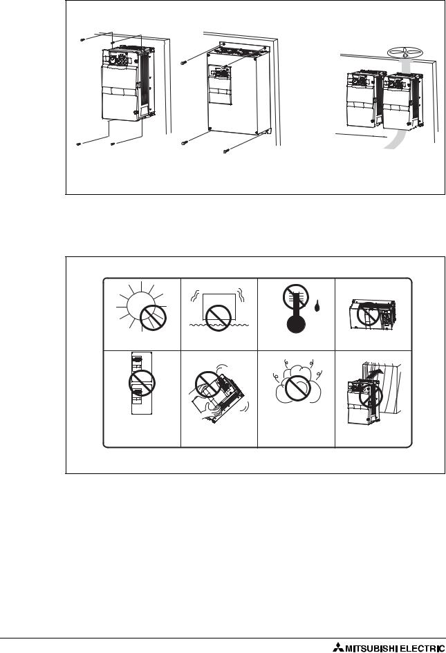
The inverter consists of precision mechanical and electronic parts. Never install or handle it in any of the following conditions as doing so could cause an operation fault or failure.
|
Direct sunlight |
Vibration (≥ 5,9 m/s²) |
High temperature, |
Horizontal placement |
|
|
(≥ 2.9m/s² for the 04320 or more) |
high humidity |
|
|
Vertical mounting |
|
|
|
|
(When installing two or more |
|
|
Mounting to combustible |
|
inverters, install them in |
Transportation by holding |
Oil mist, flammable gas, |
|
|
parallel.) |
the front cover |
corrosive gas, fluff, dust, etc. |
material |
|
|
|
|
I000998E |
Fig. 2-9: |
Conditions, that could cause an operation fault or failure |
|
||
2 - 6
 Loading...