


 Loading...
USER’S MANUAL
FX2N-5A Special function block

FX2N-5A Special function block
Foreword
•This manual contains text, diagrams and explanations which will guide the reader in the correct installation and operation of the FX2N-5A Special function block. It should be read and understood before attempting to install or use the unit.
•Further information can be found in the FX0N/FX1N/FX2N/FX2NC/FX3U/FX3UC Series Hardware Manual for connecting main unit, and the FX Series Programming Manual(ΙΙ).
•If in doubt at any stage of the installation of FX2N-5A Special function block always consult a professional electrical engineer who is qualified and trained to the local and national standards that applies to the installation site.
•If in doubt about the operation or use of FX2N-5A Special function block please consult the nearest Mitsubishi Electric distributor.
•This manual is subject to change without notice.

FX2N-5A Special function block
FX2N-5A Special function block
USER’S MANUAL
Manual number : JY997D11401
Manual revision : D
Date |
: September 2008 |
This manual confers no industrial property rights or any rights of any other kind, nor does it confer any patent licenses. Mitsubishi Electric Corporation cannot be held responsible for any problems involving industrial property rights which may occur as a result of using the contents noted in this manual.

FX2N-5A Special function block
ii

FX2N-5A Special function block
Guidelines for the Safety of the User and Protection of the FX2N-5A Special function block.
This manual provides information for the use of the FX2N-5A Special function block. The manual has been written to be used by trained and competent personnel. The definition of such a person or persons is as follows:
a)Any engineer who is responsible for the planning, design and construction of automatic equipment using the product associated with this manual, should be of a competent nature, trained and qualified to the local and national standards required to fulfill that role. These engineers should be fully aware of all aspects of safety with regards to automated equipment.
b)Any commissioning or service engineer must be of a competent nature, trained and qualified to the local and national standards required to fulfill that job. These engineers should also be trained in the use and maintenance of the completed product. This includes being completely familiar with all associated documentation for said product. All maintenance should be carried out in accordance with established safety practices.
c)All operators of the completed equipment (see Note) should be trained to use this product in a safe manner in compliance to established safety practices. The operators should also be familiar with documentation which is associated with the actual operation of the completed equipment.
Note : The term ‘completed equipment’ refers to a third party constructed device which contains or uses the product associated with this manual.
iii

FX2N-5A Special function block
Notes on the Symbols Used in this Manual
At various times throughout this manual certain symbols will be used to highlight points which are intended to ensure the users personal safety and protect the integrity of equipment. Whenever any of the following symbols are encountered its associated note must be read and understood. Each of the symbols used will now be listed with a brief description of its meaning.
Hardware Warnings
1) Indicates that the identified danger WILL cause physical and property damage.
2) Indicates that the identified danger could POSSIBLY cause physical and property damage.
3) Indicates a point of further interest or further explanation.
Software Warnings
4) Indicates special care must be taken when using this element of software.
5) Indicates a special point which the user of the associate software element should be aware.
6) Indicates a point of interest or further explanation.
iv

FX2N-5A Special function block
•Under no circumstances will Mitsubishi Electric be liable responsible for any consequential damage that may arise as a result of the installation or use of this equipment.
•All examples and diagrams shown in this manual are intended only as an aid to understanding the text, not to guarantee operation. Mitsubishi Electric will accept no responsibility for actual use of the product based on these illustrative examples.
•Please contact a Mitsubishi Electric distributor for more information concerning applications in life critical situations or high reliability.
v

FX2N-5A Special function block
Note Concerning the CE Marking
This document does not guarantee that a mechanical system including this product will comply with the following standards. Compliance to EMC standards of the entire mechanical system should be checked by the user / manufacturer. Compliance to LVD standards of the entire mechanical system should be checked by the user / manufacturer.
vi

FX2N-5A Special function block
EMC
The following products have shown compliance through direct testing (of the identified standards below) and design analysis (through the creation of a technical construction file) to the European Directive for Electromagnetic Compatibility (89/336/EEC) when used as directed by the appropriate documentation. Refer to a manual or related material of each product other than the following.
Type : Programmable Controller (Open Type Equipment)
Models : FX2N-5A manufactured
from November 1st, 2003 to April 30th, 2006 are
compliant with EN50081-2 and EN61131-2:1994+A11:1996+A12:2000 after May 1st, 2006 are compliant with EN61131-2:2003
|
Standard |
Remark |
|
|
|
EN50081-2:1993 Electromagnetic compatibility |
Compliance with all relevant aspects of the standard. |
|
|
- Generic emission standard |
(Radiated Emissions and Mains Terminal Voltage |
|
Industrial environment |
Emissions) |
|
|
|
EN61131-2:1994 Programmable controllers |
Compliance with all relevant aspects of the standard. |
|
/A11:1996 |
- Equipment requirements |
(RF Immunity, Fast Transients , ESD and Damped |
/A12:2000 |
and tests |
oscillatory wave) |
|
|
|
EN61131-2:2003 Programmable controllers |
Compliance with all relevant aspects of the standard. |
|
(Radiated Emissions, Mains Terminal Voltage |
||
|
- Equipment requirements |
Emissions, RF immunity, Fast Transients, ESD, |
|
and tests |
Surge, Voltage drops and interruptions, Conducted |
|
|
and Power magnetic fields) |
|
|
|
For more details, please contact the local Mitsubishi Electric sales site.
vii

FX2N-5A Special function block
viii
FX2N-5A Special function block |
Contents. |
||
Guideline............................................................................................................................ |
iii |
||
1. |
Introduction ......................................................................................... |
1-1 |
|
2. |
External Dimensions and Parts........................................................... |
2-1 |
|
3. |
Installation ........................................................................................... |
3-1 |
|
4. |
Connection to PLC .............................................................................. |
4-1 |
|
5. |
Wiring .................................................................................................. |
5-1 |
|
|
5.1 |
Caution............................................................................................................. |
5-1 |
|
5.2 |
Input Wiring...................................................................................................... |
5-2 |
|
5.3 |
Output Wiring ................................................................................................... |
5-3 |
6. |
Specifications ...................................................................................... |
6-1 |
|
7. |
Buffer Memory (BFM)......................................................................... |
7-1 |
|
|
7.1 |
Buffer Memories (BFM) lists ............................................................................ |
7-2 |
|
7.2 |
Details of buffer memories ............................................................................. |
7-12 |
7.2.1 |
BFM 0 input mode specification (READ/WRITE) .............................................. |
7-12 |
|
7.2.2 |
BFM 1 output mode specification (READ/WRITE) ............................................ |
7-14 |
|
7.2.3 |
BFM 2 to BFM 5 |
Number of averaging times (READ/WRITE) .......................... |
7-16 |
7.2.4 |
BFM 6 to BFM 9 |
Averaged Input Channel data (READ only) ........................... |
7-17 |
7.2.5 |
BFM 10 to BFM 13 Immediate Input Channel data (READ only) ...................... |
7-17 |
|
7.2.6 |
BFM 14 Analog Output data (READ/WRITE).................................................... |
7-17 |
|
7.2.7BFM 15 Calculated Analog output data (when direct control function is active)
|
(READ only) ...................................................................................................... |
7-17 |
7.2.8 |
BFM 16 to BFM 17 Reserved............................................................................ |
7-17 |
7.2.9 |
BFM 18 hold/ reset analog output when PLC is stopped (READ/WRITE) ........ |
7-18 |
7.2.10 |
BFM 19 setting change enable/disable (READ/WRITE) ................................... |
7-19 |
7.2.11 |
BFM 20 Initialization function (reset all values to default) (READ/WRITE) ....... |
7-20 |
ix

FX2N-5A Special function block |
Contents. |
7.2.12BFM 21 Writes I/O characteristics (offset/gain Scaling function setting)
(READ/WRITE) ................................................................................................. |
7-21 |
7.2.13 BFM 22 Convenient functions setting (READ/WRITE)...................................... |
7-22 |
7.2.14BFM 23 Set parameter for direct control between the input channel and output
channel (READ/WRITE).................................................................................... |
7-23 |
7.2.15 BFM 24 Reserved ............................................................................................. |
7-24 |
7.2.16 BFM 25 Filter-level selection register (READ/WRITE) ...................................... |
7-25 |
7.2.17 BFM 26 Upper/lower limit value alarm status (READ only)............................... |
7-28 |
7.2.18 BFM 27 A/D data sudden change detection status (READ only) ...................... |
7-30 |
7.2.19 BFM 28 Scale over status (READ/WRITE) ....................................................... |
7-32 |
7.2.20 BFM 29 Error status .......................................................................................... |
7-34 |
7.2.21 BFM 30 Model ID code (READ only)................................................................. |
7-37 |
7.2.22 BFM 31 to BFM 40 reserved ............................................................................. |
7-37 |
7.2.23 BFM 41 to BFM 44 Analog input Offset data (READ/WRITE)........................... |
7-37 |
7.2.24 BFM 45 Analog output Offset data (READ/WRITE) .......................................... |
7-37 |
7.2.25 BFM 51 to BFM 54 Analog Input Gain data (READ/WRITE) ............................ |
7-38 |
7.2.26 BFM 55 Analog output Gain data (READ/WRITE) ............................................ |
7-40 |
7.2.27 BFM 71 to BFM 74 Lower limit, alarm set value (READ/WRITE)...................... |
7-41 |
7.2.28 BFM 81 to BFM 84 Upper limit, alarm set value (READ/WRITE)...................... |
7-41 |
7.2.29 BFM 91 to BFM 94 Sudden change detection set value (READ/WRITE) ......... |
7-43 |
7.2.30BFM 99: Clears upper/lower limit value error and sudden change detection error
(READ/WRITE) ................................................................................................. |
|
7-44 |
7.2.31 BFM 101 to BFM 108 |
Peak value (minimum value) (READ only)..................... |
7-45 |
7.2.32 BFM 111 to BFM 118 |
Peak value (maximum value) (READ only).................... |
7-45 |
7.2.33 BFM 109: Peak value reset flag (minimum value) (READ/WRITE)................... |
7-46 |
|
7.2.34 BFM 119: Peak value reset flag (maximum value) (READ/WRITE).................. |
7-46 |
|
7.2.35 BFM 200 to BFM 249 |
Scaling function (READ/WRITE).................................... |
7-47 |
x

FX2N-5A Special function block Contents.
8. |
Adjustment of I/O Characteristics........................................................ |
8-1 |
|
|
8.1 |
Standard I/O characteristics............................................................................. |
8-1 |
|
8.2 |
Adjustment of I/O characteristics ..................................................................... |
8-8 |
9. |
Example program................................................................................ |
9-1 |
|
|
9.1 |
Program example for analog input/output........................................................ |
9-1 |
|
9.2 |
Outline of FROM/TO commands ..................................................................... |
9-4 |
Associated Manuals List........................................................................... |
A-1 |
||
xi

FX2N-5A Special function block |
Contents. |
xii

FX2N-5A Special function block |
Introduction 1 |
1.Introduction
The FX2N-5A analog special function block has four input channels and one output channel. The input channels receive analog signals and converts them to the comparable digital values. The output channel takes a digital value and outputs an equivalent analog signal.
1)Analog signal inputs can be selected from either voltage or current input. The applicable analog signal input is set using the TO instruction supplied by the PLC main unit.
This PLC instruction is used to select different analog input signal types for each corresponding channel.
2)The FX2N-5A can be connect to FX0N/FX1N/FX2N/FX2NC/FX3U/FX3UC series PLC
3)Up to 2 FX2N-5A units can be connected to FX0N main unit, FX0N extension unit, FX1N Main unit.
Up to 8 FX2N-5A units can be connected to FX2N/FX3U/FX3UC*1 Series PLC. Up to 4 FX2N-5A units can be connected to one FX2NC Series PLC.
For connection to the FX2NC Series PLC, an FX2NC-CNV-IF is required.
For connection to the FX3UC Series PLC, an FX2NC-CNV-IF or FX3UC-1PS-5V is required. Data transfer with the PLC is performed via buffer memories of the FX2N-5A using FROM/ TO Instructions.
*1 Up to 7 units can be connected to an FX3UC-32MT-LT PLC.
1-1

FX2N-5A Special function block |
Introduction 1 |
MEMO
1-2
FX2N-5A Special function block |
External Dimensions and Parts 2 |
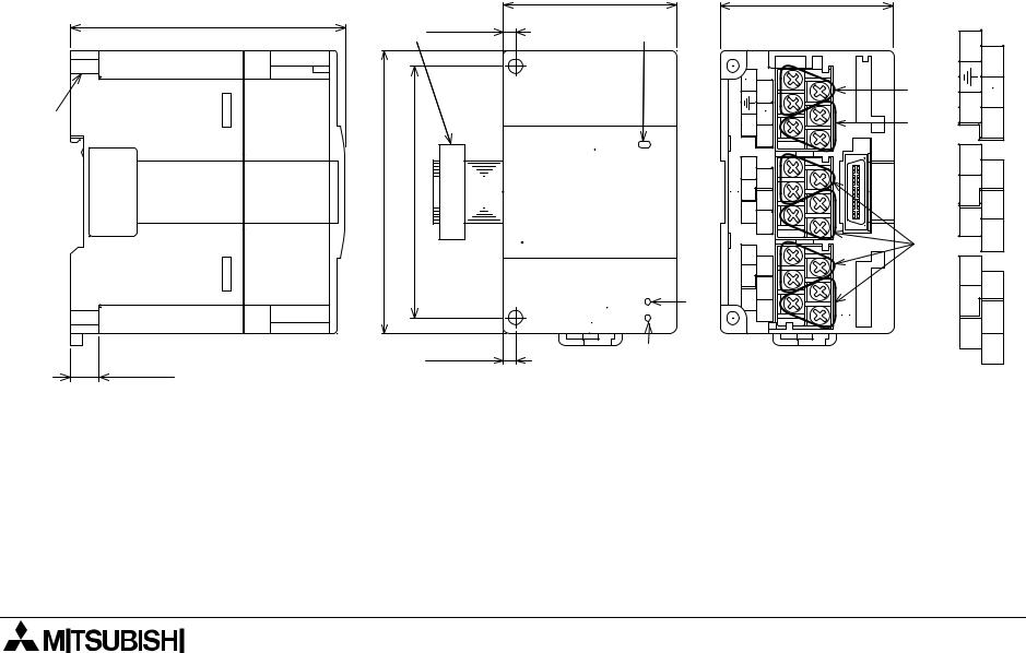
2.External Dimensions and Parts
87(3.43")
1)
10)
9)
9(0.35")
55(2.17")
2) 4(0.16")
90(3.54") |
80(3.15") |
POWER |
|
FX2N-5A |
|||
|
|
||
|
|
24V |
|
|
|
AD/DA |
|
|
|
4(0.16") |
Dimensions: mm(inches)
|
|
|
55(2.17") |
Terminal |
|
|||
3) |
|
|
|
|
arrangement |
|||
|
|
|
|
|
|
24+ |
|
|
|
|
|
|
|
|
|
24 |
|
|
|
24+ |
|
|
|
|
|
- |
|
|
I+V+ -24 |
|
4) |
OUT |
-VI |
I+ V+ |
|
|
-VI OUT |
|
||||||
|
|
5) |
||||||
|
|
|
|
|
|
|
|
|
|
IN2 IN1 |
-VI I+ V+ |
I+ V+ -VI |
|
6) |
IN2 IN1 |
-VI I+ V+ |
I+ V+ -VI |
|
|
V+ |
|
|
|
|
|
|
|
IN4IN3 |
I+V+-VI |
5A |
|
IN4IN3 |
-VII+ |
I+-VIV+ |
|
|
-VII+ |
|
||||||
|
|
|
|
|
|
|
V+ |
|
7) |
|
|
|
|
|
|
|
|
8) |
|
|
|
|
|
|
|
|
Mass (Weight): 0.3kg (0.66lbs)
2-1

FX2N-5A Special function block |
External Dimensions and Parts 2 |
1)Direct mounting hole (2-φ4.5) (0.18)
2)Extension cable
3)Power indicator lamp (LED)
5V power is supplied from the programmable controller to light this indicator lamp.
4)Power supply terminals (Screw terminal: M3 (0.12))
5)Analog output terminals (Screw terminal: M3 (0.12))
6)Analog input terminals (Screw terminal: M3 (0.12))
7)24V power indicator lamp (LED) 24V DC power is supplied to the terminals of the FX2N-5A to light this indicator lamp.
8)AD/DA conversion indicator lamp (LED)
Flashes at a high speed if AD/DA conversion is performing without a problem.
9)DIN rail mounting clip
10)DIN rail mounting slot (width of DIN rail: 35mm 1.38")
2-2

FX2N-5A Special function block |
Installation 3 |
3.Installation
Install the FX2N-5A to the right side of a main unit, extension unit, extension block or special block of the FX0N/FX1N/FX2N/FX2NC/FX3U/FX3UC Series PLC.
The FX2N-5A can be installed with DIN rail (DIN46277 of 35 mm in width) or directly installed with screws M4. For the details, refer to the handy manual supplied together with the PLC main unit.)
3-1

FX2N-5A Special function block |
Installation 3 |
Figure 3.1: Installation with DIN rail
POWER
FX2N-5A
24V
AD/DA
Hook for DIN rail
Figure 3.2: Direct installation
Installation |
screw M4 |
80(3.15) |
51(2.01) |
Dimensions: mm(inch)
•The FX2N-5A can be installed on DIN rail (DIN46277) of 35 mm in width as it is. For removal, pull down on the DIN rail mounting hook, then remove the FX2N-5A.
•The FX2N-5A can be installed directly by inserting screws (M4) into installation holes. For the pitch and the position of installation holes, refer to the figure on the left.
3-2
FX2N-5A Special function block |
Connection to PLC 4 |
4.Connection to PLC
Connect the FX2N-5A to the right side of a main unit, extension unit or extension block of FX0N/ FX1N/FX2N/FX2NC/FX3U/FX3UC Series PLC with an extension cable.
For connection to a basic unit or extension block of the FX2NC Series PLC, use an FX2NC-CNV- IF.
For connection to a basic unit or extension block of the FX3UC Series PLC, use an FX2NC-CNV- IF or FX3UC-1PS-5V.
Please check the power supply availability to determine the number of FX2N-5A blocks that can be connected to the FX0N/FX1N/FX2N/FX2NC/FX3U/FX3UC PLCs.
A unit No. 0 to 7 is automatically assigned to each special unit or special block connected to a PLC basic unit from the one nearest to the basic unit.*1
The data is read from and written to the FX2N-5A by FROM/TO instructions supplied by the main unit.
*1 Because the unit No.0 is assigned to the built-in CC-Link/LT master in the FX3UC-32MT-LT, unit numbers assigned to special extension units/blocks begins with No.1.
4-1

FX2N-5A Special function block |
Connection to PLC 4 |
MEMO
4-2

FX2N-5A Special function block |
Wiring 5 |
5.Wiring
5.1Caution
1) Do not lay signal cabling near to high voltage power cabling or house them in the same trunking duct. Effects of noise or surge induction may occur. Keep signal cables at safe distance of more than 100 mm (3.94") from these power cables.
2)The terminal screws of the FX2N-5A are M3 (0.12"), therefore crimp style terminals (see drawing) suitable for use with these screws should be fitted to the cable for wiring.
Figure 5.1: Crimp Terminals
For M3 (0.12") |
For M3 (0.12") |
|
6.2 mm (0.24" ) |
6.2 mm (0.24") |
|
or less |
||
or less |
||
|
3)The terminal tightening torque is 0.5 to 0.8 Nxm. Tighten securely to avoid malfunction.
4)Cut off all phases of power source before installation or performing wiring work in order to avoid electric shock or product damage.
5)Remount the provided terminal cover before supplying power and operating the unit after installation or wiring work in order to avoid electric shock.
5-1

FX2N-5A Special function block |
Wiring 5 |
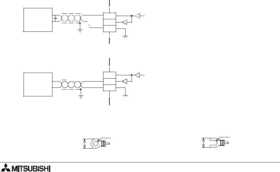
5.2Input Wiring
Figure 5.2: Input Wiring
|
|
|
|
FX2N-5A |
|
*5 |
|
|
24+ |
|
+15V |
|
|
DC/DC |
|
||
24V DC |
|
24- |
AG |
||
|
converter |
||||
*4 |
" |
|
|||
Connected to " |
|
|
|
|
|
terminal of PLC |
|
|
|
|
-15V |
main unit |
Class D |
|
|
|
|
|
|
|
|
|
|
grounding |
IN1 |
|
4.7kΩ |
|
|
Voltage |
|
V+ |
|
||
input |
|
*2 |
250Ω |
CH1 |
|
|
I+ |
||||
|
*1 |
200kΩ |
|||
|
|
VI- |
|
||
|
Shielded |
|
|
|
|
|
|
|
|
|
|
Current |
cable |
IN2 |
|
4.7kΩ |
|
|
V+ |
|
|||
|
|
|
|
||
input |
|
*3 |
250Ω |
CH2 |
|
|
I+ |
||||
|
|
|
200kΩ |
||
|
|
|
VI- |
|
|
|
|
|
|
|
|
|
|
IN4 |
V+ |
4.7kΩ |
|
|
|
|
250Ω |
CH4 |
|
|
|
|
I+ |
||
|
|
|
200kΩ |
||
|
|
|
VI- |
|
|
|
|
|
|
|
|
|
|
|
|
AG |
|
*1 Use a two-core, shielded twisted pair for the analog input line, and separate it from other power lines or a lines easily induced.
*2 If there is voltage ripple in the input signal or there is noise in the external wiring, connect a bipolar capacitor of approximately 0.1 to 0.47 µF, 25 V.
*3 For the current input, short-circuit the “V+” terminal and the “I+” terminal.
*4 Make sure to connect the 

 terminal to the

 terminal of the PLC basic unit to which Class D grounding (100 Ω or less) is performed.
*5 The 24 V DC service power supply of the PLC is also available.
-For the terminal arrangement, refer to Section 2.
5-2
FX2N-5A Special function block |
Wiring 5 |
5.3Output Wiring
Please refer to 5.2 for the wiring for "24+", "24-" terminals.
Figure 5.3: Output Wiring
Voltage output *1 |
FX2N-5A |
|
|
||
|
Shielded cable |
OUT |
Inverter, |
|
V+ |
etc. |
*3 |
I+ |
|
VI- |
|
|
*2 |
|
|
|
|
|
|
|
FX2N-5A |
Current output |
*1 |
OUT |
|
|
N.C. |
V+ |
|
|
Shielded cable |
||
Recorder, |
|
|
I+ |
etc. |
|
|
VI- |
|
*2 |
|
|
*1 Use a twisted pair shielded cable for the analog output. This cable should be wired away from power lines or any other lines which could induce noise.
*2 Apply 1-point grounding at the load side of the output cable (grounding: 100Ω or less).
*3 If electrical noise or a voltage ripple exists at the output, connect a smoothing capacitor of
0.1to 0.47µF, 25V.
-Shorting the voltage output terminal or connecting the current output load to the voltage output terminal may damage the FX2N-5A.
-For the terminal arrangement, refer to Section 2.
Figure 5.4: Crimp Terminals
For M3 (0.12") |
For M3 (0.12") |
|
6.2 mm (0.24" ) |
6.2 mm (0.24") |
|
or less |
||
or less |
||
|
5-3

FX2N-5A Special function block |
Wiring 5 |
MEMO
5-4

FX2N-5A Special function block |
Specifications 6 |
6.Specifications
Table 6.1: General specifications
|
|
|
|
|
Item |
Specifications |
|
|
Ambient |
0 to +55 °C during operation, -20 to +70 °C during storage |
|
|
temperature range |
|
|
|
|
|
|
|
|
|
|
|
Ambient humidity |
35 to 85 % RH during operation (Dew condensation shall not be allowed.) |
|
|
|
|
|
|
|
Frequency 10 to 57 Hz, half amplitude 0.075 mm, 57 to 150 Hz, acceleration 9.8 |
|
|
Vibration resistance |
m/s2, 10 times in each of X, Y and Z directions (80 min. in each direction) |
|
|
(For product installed with DIN rail: Frequency 10 to 57 Hz, half amplitude 0.035 |
|
|
|
|
mm, 57 to 150 Hz, acceleration 4.9 m/s2) |
|
|
Impact resistance |
147 m/s2 for 11 ms, 3 times in each of X, Y and Z directions with half-sine pulses |
|
|
Noise resistance |
By noise simulator of noise voltage 1,000 Vp-p, noise width 1 µs and frequency |
|
|
30 to 100 Hz |
|
|
|
|
|
|
|
|
|
|
|
Withstand voltage |
500 V AC for 1 min |
|
|
(between analog input terminal and each terminal of PLC main unit) |
|
|
|
|
|
|
|
|
|
|
|
Insulation resistance |
5 MΩ or more by 500 V DC Megger (between all terminals as a whole and earth) |
|
|
|
|
|
|
Operating |
Corrosive gas and much dusts shall not be detected. |
|
|
atmosphere |
|
|
|
|
|
|
|
|
|
|
|
Working altitude |
<2000m*1 |
|
|
|
|
|
*1 If the pressure is higher than the atmospheric pressure, do not use FX2N-8AD. Malfunctions may occur.
6-1

FX2N-5A Special function block Specifications 6
Table 6.2: Power supply specifications
|
|
|
|
|
Item |
Specifications |
|
|
|
|
|
|
Interface driving |
24 V DC±10%, 90 mA (maximum), externally supplied |
|
|
power supply |
|
|
|
|
|
|
|
|
|
|
|
CPU driving power |
5 V DC, 70 mA, supplied via extension cable from PLC main unit |
|
|
supply |
|
|
|
|
|
|
|
|
|
|
|
|
|
|
Table 6.3: Performance specifications
|
|
|
|
|
Item |
Specifications |
|
|
|
|
|
|
|
Channel for voltage/current input: 1 ms x Number of used channels |
|
|
Conversion speed |
Channel for voltage/current output: 2 ms |
|
|
|
(See BFM 25) |
|
|
|
|
|
|
|
Photocoupler insulates the analog input/output area from PLC. |
|
|
Insulation method |
DC/DC converter insulates the power supply from analog I/O. |
|
|
|
Channels are not insulated against each other. |
|
|
|
|
|
|
Number of occupied |
8 points (including input and output points) |
|
|
I/O points |
|
|
|
|
|
|
|
|
FX0N, FX1N, FX2N, FX2NC, FX3U, FX3UC Series PLC |
|
|
Applicable PLC |
For connection to the FX2NC Series PLC, an FX2NC-CNV-IF is required. |
|
|
For connection to the FX3UC Series PLC, an FX2NC-CNV-IF or FX3UC-1PS-5V is |
|
|
|
|
|
|
|
|
required. |
|
|
|
|
|
|
Built-in memory |
EEPROM |
|
|
|
|
|
|
|
|
|
6-2

FX2N-5A Special function block Specifications 6
Table 6.4: Voltage/current input specifications
|
|
|
|
|
|
Item |
Voltage input |
Current input |
|
|
|
|
|
|
|
|
-10 to +10 V DC |
|
|
|
|
(input resistance: 200 kΩ) |
|
|
|
|
Adjustment is enabled with the |
|
|
|
|
following conditions: |
-20 to +20 mA DC, +4 to +20 mA DC |
|
|
|
Offset value: -32000 to +5000 mV |
|
|
|
|
(input resistance: 250 Ω) |
|
|
|
|
Gain value: -5000 to +32000 mV |
|
|
|
|
Adjustment is enabled with the |
|
|
|
|
"Gain - Offset": > 1000 mV |
|
|
|
|
-100 to +100mV DC |
following conditions: |
|
|
|
Offset value: -32000 to +10000 µA |
|
|
|
|
(input resistance: 200kΩ) |
|
|
|
Analog input range |
Gain value: -10000 to +32000 µA |
|
|
|
Adjustment is enabled with the |
|
||
|
|
"Gain - Offset": > 1000 µA |
|
|
|
|
following conditions: |
|
|
|
|
(Resolution is constant.) |
|
|
|
|
Offset value: -320000 to +50000µV |
|
|
|
|
Change is disabled while the |
|
|
|
|
Gain value: -50000 to +320000µV |
|
|
|
|
Amperemeter display mode is used. |
|
|
|
|
"Gain - Offset": > 10000 µV |
|
|
|
|
Maximum absolute input: ±30 mA |
|
|
|
|
(Resolution is constant.) |
|
|
|
|
|
|
|
|
|
Change is disabled while the Voltmeter |
|
|
|
|
display mode is used. |
|
|
|
|
Maximum absolute input: ±15 V |
|
|
|
|
|
|
|
|
|
Signed 16-bit binary |
|
|
|
Digital output |
(-10 to +10V at input) |
Signed 15-bit binary |
|
|
Signed 12-bit binary |
|
||
|
|
|
|
|
|
|
(-100 to +100mV at input) |
|
|
|
|
|
|
|
|
|
|
|
|
6-3

FX2N-5A Special function block Specifications 6
Table 6.4: Voltage/current input specifications
|
|
|
|
|
|
Item |
Voltage input |
Current input |
|
|
|
|
|
|
|
|
|
• 10 µA (40 mA × 1/4000) |
|
|
|
|
-20 to +20 mA at input |
|
|
|
• 312.5 µV (20 V × 1/64000) |
• 1.25 µA (40 mA × 1/32000) |
|
|
Resolution |
-10 to +10V at input |
-20 to +20 mA at input |
|
|
• 50µV (200 mV × 1/4000) |
• 10 µA (40 mA × 1/4000) |
|
|
|
|
|
||
|
|
-100 to +100mV at input |
+4 to +20 mA at input |
|
|
|
|
• 1.25 µA (40 mA × 1/32000) |
|
|
|
|
+4 to +20 mA at input |
|
|
|
|
|
|
|
|
Ambient temperature: 25 °C ± 5 °C |
Ambient temperature: 25 °C ± 5 °C |
|
|
|
-10 to +10V DC : |
|
|
|
|
-20 to +20mA DC : |
|
|
|
|
±0.3% (±60 mV) against full scale 20V |
|
|
|
|
±0.5% (±200 µA) against full scale 40 |
|
|
|
|
-100 to +100mV DC : |
mA |
|
|
|
±0.5% (±100 mV) against full scale 20V |
|
|
|
Total accuracy |
+4 to +20mA input is same (±200 µA) |
|
|
|
Ambient temperature: 0 to +55 °C |
Ambient temperature: 0 to +55 °C |
|
|
|
|
-10 to +10V DC : |
|
|
|
|
-20 to +20mA DC : |
|
|
|
|
±0.5% (±100 mV) against full scale |
|
|
|
|
±1.0% (±400 µA) against full scale |
|
|
|
|
20V |
|
|
|
|
40 mA |
|
|
|
|
-100 to +100mV DC : |
|
|
|
|
+4 to +20mA input is same (±400 µA) |
|
|
|
|
±1.0% (±200 mV) against full scale 20V |
|
|
|
|
|
|
|
|
|
|
|
|
6-4
Loading...