


 Loading...
11B-0-1
ENGINE
4M41
CONTENTS
GENERAL INFORMATION . . . . . . . . . . . . . . . . . . . . . . . . . . . . . . . . . . . . . . . . . . . . . |
. . . . . . 11B-0-3 |
|
1. |
SPECIFICATIONS . . . . . . . . . . . . . . . . . . . . . . . . . . . . . . . . . . . . . . . . . . . . . . . . . |
. . . . . . 11B-1-1 |
|
SERVICE SPECIFICATIONS . . . . . . . . . . . . . . . . . . . . . . . . . . . . . . . . . . . . . . |
. . . . . . 11B-1-1 |
|
TORQUE SPECIFICATIONS . . . . . . . . . . . . . . . . . . . . . . . . . . . . . . . . . . . . . . |
. . . . . . 11B-1-4 |
|
SEALANT . . . . . . . . . . . . . . . . . . . . . . . . . . . . . . . . . . . . . . . . . . . . . . . . . . . . . |
. . . . . . 11B-1-8 |
2. |
SPECIAL TOOLS . . . . . . . . . . . . . . . . . . . . . . . . . . . . . . . . . . . . . . . . . . . . . . . . . |
. . . . . . 11B-2-1 |
3. |
GENERATOR ASSEMBLY . . . . . . . . . . . . . . . . . . . . . . . . . . . . . . . . . . . . . . . . . |
. . . . . . 11B-3-1 |
4. |
GLOW PLUG . . . . . . . . . . . . . . . . . . . . . . . . . . . . . . . . . . . . . . . . . . . . . . . . . . . . . |
. . . . . . 11B-4-1 |
5. |
COOLING FAN, V-BELT AND WATER PUMP . . . . . . . . . . . . . . . . . . . . . . . . . |
. . . . . . 11B-5-1 |
6. |
WATER HOSES AND PIPES . . . . . . . . . . . . . . . . . . . . . . . . . . . . . . . . . . . . . . . . |
. . . . . . 11B-6-1 |
7. |
THERMOSTAT . . . . . . . . . . . . . . . . . . . . . . . . . . . . . . . . . . . . . . . . . . . . . . . . . . . . |
. . . . . . 11B-7-1 |
8. |
EGR VALVE ASSEMBLY . . . . . . . . . . . . . . . . . . . . . . . . . . . . . . . . . . . . . . . . . . . |
. . . . . . 11B-8-1 |
9. |
INTAKE MANIFOLD . . . . . . . . . . . . . . . . . . . . . . . . . . . . . . . . . . . . . . . . . . . . . . . |
. . . . . . 11B-9-1 |
10. |
TURBOCHARGER ASSEMBLY . . . . . . . . . . . . . . . . . . . . . . . . . . . . . . . . . . . . . |
. . . . 11B-10-1 |
11. EXHAUST MANIFOLD . . . . . . . . . . . . . . . . . . . . . . . . . . . . . . . . . . . . . . . . . . . . . |
. . . . . 11B-11-1 |
|
12. |
INJECTION PUMP ASSEMBLY . . . . . . . . . . . . . . . . . . . . . . . . . . . . . . . . . . . . . |
. . . . 11B-12-1 |
13. |
INJECTION PUMP GEAR . . . . . . . . . . . . . . . . . . . . . . . . . . . . . . . . . . . . . . . . . . |
. . . . 11B-13-1 |
14. |
ROCKER COVER, CAMSHAFT HOLDER ASSEMBLY AND CAMSHAFT |
. . . . 11B-14-1 |
15. |
INJECTION NOZZLE . . . . . . . . . . . . . . . . . . . . . . . . . . . . . . . . . . . . . . . . . . . . . . |
. . . . 11B-15-1 |
16. |
CYLINDER HEAD AND VALVE MECHANISM . . . . . . . . . . . . . . . . . . . . . . . . . |
. . . . 11B-16-1 |
17. |
VACUUM PUMP . . . . . . . . . . . . . . . . . . . . . . . . . . . . . . . . . . . . . . . . . . . . . . . . . . |
. . . . 11B-17-1 |
18. |
TIMING GEAR CASE . . . . . . . . . . . . . . . . . . . . . . . . . . . . . . . . . . . . . . . . . . . . . . |
. . . . 11B-18-1 |
19. |
TIMING GEAR AND BALANCE SHAFT . . . . . . . . . . . . . . . . . . . . . . . . . . . . . . |
. . . . 11B-19-1 |
20. |
OIL PUMP . . . . . . . . . . . . . . . . . . . . . . . . . . . . . . . . . . . . . . . . . . . . . . . . . . . . . . . . |
. . . . 11B-20-1 |
21. |
OIL COOLER AND OIL FILTER . . . . . . . . . . . . . . . . . . . . . . . . . . . . . . . . . . . . . |
. . . . 11B-21-1 |
22. |
OIL PAN, OIL STRAINER AND OIL JET . . . . . . . . . . . . . . . . . . . . . . . . . . . . . . |
. . . . 11B-22-1 |
23. |
PISTON AND CONNECTING ROD . . . . . . . . . . . . . . . . . . . . . . . . . . . . . . . . . . |
. . . . 11B-23-1 |
24. |
DRIVE PLATE . . . . . . . . . . . . . . . . . . . . . . . . . . . . . . . . . . . . . . . . . . . . . . . . . . . . |
. . . . 11B-24-1 |
25. |
CRANK SHAFT AND CRANK CASE . . . . . . . . . . . . . . . . . . . . . . . . . . . . . . . . |
. . . . 11B-25-1 |
26. |
BALANCE SHAFT BUSH . . . . . . . . . . . . . . . . . . . . . . . . . . . . . . . . . . . . . . . . . . |
. . . . 11B-26-1 |
|
|
|
|
|
|
E Mitsubishi Motors Corporation |
Feb. 2000 |
PWEE9409-D |
Added |

11B-0-2
NOTES
E Mitsubishi Motors Corporation |
Feb. 2000 |
PWEE9409-D |
Added |

4M41 ENGINE - General Information |
11B-0-3 |
|
|
|
|
GENERAL INFORMATION |
|
|
|
|
|
Descriptions |
Specifications |
|
|
|
|
Total displacement dm3 |
3200 |
|
No. and arrangement of cylinders |
4 in-line |
|
|
|
|
Combustion chamber |
Direct injection |
|
|
|
|
No. of intake/exhaust valves (per cylinder) |
2 each |
|
|
|
|
Valve mechanism |
Double overhead camshaft, 4-valve |
|
|
|
|
Cylinder bore x stroke mm |
98.5 x 10⁵ |
|
|
|
|
Compression ratio |
17 |
|
|
|
|
Supercharger |
Turbo-charging type |
|
|
|
|
Intercooler |
Air-cooling type |
|
|
|
|
Fuel supply |
Distributor type electronically controlled fuel injection pump |
|
|
|
|
E Mitsubishi Motors Corporation |
Feb. 2000 |
PWEE9409-D |
Added |

|
4M41 ENGINE - Specifications |
|
|
11B-1-1 |
|||||
|
|
|
|
|
|
|
|
|
|
1. SPECIFICATIONS |
|
|
|
|
|
|
|
|
|
SERVICE SPECIFICATIONS |
|
|
|
|
|
|
|
Unit: mm |
|
|
|
|
|
|
|
|
|
|
|
|
|
|
|
|
|
|
|
|
|
Descriptions |
|
|
|
|
|
|
Standard |
Limit |
|
|
|
|
|
|
|
|
|
|
|
Glow plug |
|
|
|
|
|
|
|
|
|
|
|
|
|
|
|
|
|
|
|
Glow plug |
Resistance W |
|
|
|
|
|
1.1 |
|
- |
|
|
|
|
|
|
|
|
|
|
Turbocharger assembly |
|
|
|
|
|
|
|
|
|
|
|
|
|
|
|
|
|
|
|
Turbocharger |
Actuator operating pressure |
|
|
|
|
161 |
|
- |
|
|
(when operating 1 mm) |
kPa |
|
|
|
|
|||
|
|
|
|
|
|
|
|
||
Rocker cover, camshaft holder assembly, camshaft assembly |
|
|
|
|
|||||
|
|
|
|
|
|
|
|
|
|
Camshaft |
End play |
|
|
|
|
|
0.10 - 0.18 |
0.3 |
|
|
|
|
|
|
|
|
|
|
|
|
Cam lobe lift |
Intake |
|
|
Front |
|
6.16 |
|
6.11 |
|
|
|
|
|
|
|
|
|
|
|
|
|
|
|
Rear |
|
6.10 |
|
6.05 |
|
|
|
|
|
|
|
|
|
|
|
|
Exhaust |
|
|
Front |
|
5.91 |
|
5.86 |
|
|
|
|
|
|
|
|
|
|
|
|
|
|
|
Rear |
|
6.16 |
|
6.11 |
|
|
|
|
|
|
|
|
|
|
|
Bend |
|
|
|
|
|
Less than 0.015 |
0.03 |
|
|
|
|
|
|
|
|
|
|
|
|
Journal oil clearance |
|
|
|
|
0.05 |
- 0.09 |
0.15 |
|
|
|
|
|
|
|
|
|
|
|
Rocker |
Rocker roller radial play |
|
|
|
|
0.03 |
- 0.07 |
- |
|
|
|
|
|
|
|
|
|
|
|
Injection nozzle |
|
|
|
|
|
|
|
|
|
|
|
|
|
|
|||||
Injection nozzle |
Injection pressure |
No. 1 valve opening pressure |
17.60 - 18.58 |
- |
|||||
|
(valve opening |
|
|
|
|
MPa |
|
|
|
|
pressure) |
|
|
|
|
|
|
|
|
|
No. 2 valve opening pressure |
22.6 |
- 23.6 |
- |
|||||
|
|
||||||||
|
|
|
|
|
|
MPa |
|
|
|
|
|
|
|
|
|
|
|
|
|
|
Pre-lift |
|
|
|
|
|
0.05 |
- 0.07 |
- |
|
|
|
|
|
|
|
|
|
|
|
Needle valve lift |
|
|
|
|
|
0.23 |
- 0.28 |
- |
|
|
|
|
|
|
|
|
|
|
Cylinder head and valve mechanism |
|
|
|
|
|
|
|
|
|
|
|
|
|
|
|
|
|
|
|
Valve spring |
Free height |
|
|
|
|
|
51.3 |
|
- |
|
|
|
|
|
|
|
|
|
|
|
Load (installed height: 39.5) |
N |
|
|
|
255 |
|
- |
|
|
|
|
|
|
|
|
|
|
|
|
Out-of-squareness |
|
|
|
|
|
2_ |
|
4_ |
|
|
|
|
|
|
|
|
||
Valve |
Intake |
Stem diameter |
|
|
|
6.560 - 6.575 |
6.45 |
||
|
|
|
|
|
|
|
|
|
|
|
|
Sinkage |
from |
cylinder |
head |
0.05 |
- 0.55 |
0.8 |
|
|
|
bottom |
|
|
|
|
|
|
|
|
|
|
|
|
|
|
|
|
|
|
|
Margin |
|
|
|
|
1.0 |
|
0.8 |
|
|
|
|
|
|
|
|
||
|
|
Valve seat angle |
|
|
|
45_ ± 15’ |
- |
||
|
|
|
|
|
|
|
|
||
|
Exhaust |
Stem diameter |
|
|
|
6.53 - 6.55 |
6.45 |
||
|
|
|
|
|
|
|
|
|
|
|
|
Sinkage |
from |
cylinder |
head |
0.05 |
- 0.55 |
0.8 |
|
|
|
bottom |
|
|
|
|
|
|
|
|
|
|
|
|
|
|
|
|
|
|
|
Margin |
|
|
|
|
1.0 |
|
0.8 |
|
|
|
|
|
|
|
|
||
|
|
Valve seat angle |
|
|
|
45_ ± 15’ |
- |
||
|
|
|
|
|
|
|
|
|
|
Valve guide |
Stem-to-guide clearance |
|
|
Intake |
|
0.02 |
- 0.06 |
0.10 |
|
|
|
|
|
|
|
|
|
||
|
|
|
|
|
Exhaust |
0.05 - 0.09 |
0.15 |
||
|
|
|
|
|
|
|
|
|
|
E Mitsubishi Motors Corporation |
Feb. 2000 |
PWEE9409-D |
Added |

11B-1-2 |
4M41 ENGINE - Specifications |
|
|
|
||
|
|
|
|
|
|
|
|
|
|
|
|
|
|
Descriptions |
|
|
|
Standard |
Limit |
|
|
|
|
|
|
|
|
Valve seat |
Seat width |
|
|
1.8 - 2.2 |
2.8 |
|
|
|
|
|
|
|
|
Cylinder head |
Bottom surface distortion |
|
Less than 0.05 |
0.2 |
||
|
|
|
|
|
|
|
Vacuum pump |
|
|
|
|
|
|
|
|
|
|
|
||
Vacuum pump |
Performance |
Attained degree of vacuum |
93 kPa or more |
- |
||
|
|
|
|
|
||
|
|
Pump speed |
1500 r/min |
- |
||
|
|
|
|
|
|
|
Timing gears and balance shafts |
|
|
|
|
|
|
|
|
|
|
|||
Backlash between gears |
Balance shaft gear RH and oil pump gear |
0.04 - 0.19 |
0.3 |
|||
|
|
|
|
|||
|
Oil pump gear and crankshaft gear |
0.04 - 0.18 |
0.3 |
|||
|
|
|
|
|
||
|
Crankshaft gear and idler gear |
0.04 |
- 0.18 |
0.3 |
||
|
|
|
|
|
|
|
|
Idler gear and idler gear LH |
|
0.04 |
- 0.19 |
0.3 |
|
|
|
|
|
|||
|
Idler gear LH and balance shaft gear LH |
0.04 - 0.22 |
0.4 |
|||
|
|
|
|
|
||
|
Idler gear and injection pump gear |
0.04 |
- 0.21 |
0.4 |
||
|
|
|
|
|
||
End play |
Balance shaft LH, RH |
|
0.09 - 0.24 |
0.3 |
||
|
|
|
|
|
||
|
Idler gear/sprocket assembly |
0.05 |
- 0.20 |
0.3 |
||
|
|
|
|
|
||
|
Idler gear LH assembly |
|
0.05 - 0.20 |
0.3 |
||
|
|
|
|
|
||
Timing chain elongation (minimum distance between chain spans facing each |
16.5 |
|
9 |
|||
other when pressing on tensioner lever) |
|
|
|
|
|
|
|
|
|
|
|
|
|
Tension lever-to-tension lever shaft clearance |
|
|
0.06 |
- 0.18 |
0.3 |
|
|
|
|
|
|
|
|
Idler gear bush LH-to-idler shaft clearance |
|
|
0.02 |
- 0.05 |
0.1 |
|
|
|
|
|
|
|
|
Idler sprocket bush-to-idler shaft clearance |
|
|
0.02 |
- 0.06 |
0.1 |
|
|
|
|
|
|
|
|
Oil pump |
|
|
|
|
|
|
|
|
|
|
|
||
Oil pump |
Driven gear shaft-to-oil pump case and cover |
0.03 |
- 0.05 |
0.15 |
||
|
clearance |
|
|
|
|
|
|
|
|
|
|
|
|
|
Side clearance |
|
|
0.05 |
- 0.10 |
0.15 |
|
|
|
|
|
|
|
|
Tip clearance |
|
|
0.15 |
- 0.26 |
0.27 |
|
|
|
|
|
|
|
Oil cooler and oil filter |
|
|
|
|
|
|
|
|
|
|
|
||
Bypass valve spring |
Valve opening pressure |
kPa |
490 ± 30 |
- |
||
|
|
|
|
|
||
Regulator valve spring |
Valve opening pressure |
kPa |
620 ± 30 |
- |
||
|
|
|
|
|
|
|
Piston and connecting rod assembly |
|
|
|
|
|
|
|
|
|
|
|
|
|
Piston |
Protrusion |
|
|
-0.20 - - 0.30 |
- |
|
|
|
|
|
|
||
Piston pin |
Piston pin-to-connecting rod bush clearance |
0.03 |
- 0.05 |
0.1 |
||
|
|
|
|
|||
|
Piston pin-to-piston clearance |
0.007 - 0.021 |
0.05 |
|||
|
|
|
|
|
|
|
Piston ring |
Ring-to-ring |
No.1 compression ring |
0.03 |
- 0.08 |
0.15 |
|
|
groove clearance |
|
|
|
|
|
|
No.2 compression ring |
0.07 - 0.10 |
0.15 |
|||
|
|
|||||
|
|
|
|
|
|
|
|
|
Oil ring |
|
0.03 |
- 0.06 |
0.15 |
|
|
|
|
|
||
|
End gap |
No.1 compression ring |
0.3 - 0.45 |
0.8 |
||
|
|
|
|
|
||
|
|
No.2 compression ring |
0.4 - 0.55 |
0.8 |
||
|
|
|
|
|
|
|
|
|
Oil ring |
|
0.3 - 0.5 |
0.8 |
|
|
|
|
|
|
|
|
E Mitsubishi Motors Corporation |
Feb. 2000 |
PWEE9409-D |
Added |

|
4M41 ENGINE - Specifications |
|
|
11B-1-3 |
|
|
|
|
|
|
|
|
|
|
|
|
|
Descriptions |
|
|
Standard |
Limit |
|
|
|
|
|
|
|
Connecting rod |
End play |
|
0.15 |
- 0.45 |
0.6 |
|
|
|
|
|
|
|
Bend |
|
- |
|
0.05 |
|
|
|
|
|
|
|
Twist |
|
- |
|
0.1 |
|
|
|
|
|
|
Connecting rod bearing |
Oil clearance |
|
0.03 |
- 0.05 |
0.1 |
|
|
|
|
|
|
|
Free span |
|
- |
|
58.8 max. |
|
|
|
|
|
|
Crankshaft and crankcase |
|
|
|
|
|
|
|
|
|
|
|
Crankshaft |
End play |
|
0.10 |
- 0.28 |
0.4 |
|
|
|
|
|
|
|
Bend |
|
Less than 0.02 |
0.05 |
|
|
|
|
|
|
|
|
Pin and journal |
Out-of-roundness |
Less than 0.01 |
- |
|
|
|
|
|
|
|
|
|
Conicity |
Less than 0.006 |
- |
|
|
|
|
|
|
|
Main bearing |
Main bearing-to- |
No.1, 2, 4 and 5 journal |
0.04 |
- 0.06 |
0.1 |
|
crankshaft clear- |
|
|
|
|
|
No.3 journal |
0.06 |
- 0.08 |
0.1 |
|
|
ance |
||||
|
|
|
|
|
|
|
Free span |
|
- |
|
73.16 max. |
|
|
|
|
||
Upper crankcase |
Upper surface distortion |
Less than 0.05 |
0.1 |
||
|
|
|
|
|
|
|
Cylinder I.D. |
|
98.5 |
- 98.53 |
98.75 |
|
|
|
|
|
|
|
Piston and connecting rod assembly-to-upper |
0.04 |
- 0.05 |
- |
|
|
crankcase cylinder clearance |
|
|
|
|
|
|
|
|
|
|
Balance shaft bush |
|
|
|
|
|
|
|
|
|
|
|
Balance shaft |
Clearance between balance shaft and balance shaft |
0.06 |
- 0.11 |
0.16 |
|
|
bush |
|
|
|
|
|
|
|
|
|
|
E Mitsubishi Motors Corporation |
Feb. 2000 |
PWEE9409-D |
Added |

11B-1-4 |
4M41 ENGINE - Specifications |
|
||
|
|
|
|
|
TORQUE SPECIFICATIONS |
|
|
||
|
|
|
|
|
Items |
|
|
Torque Nm |
|
|
|
|
|
|
Glow plug |
|
|
|
|
|
|
|
|
|
Connection plate |
|
|
1.3 ± 1 |
|
|
|
|
|
|
Glow plug |
|
|
18 |
± 1 |
|
|
|
|
|
Cooling fan V-belt and water pump |
|
|
||
|
|
|
|
|
Cooling fan bolt |
|
|
10 |
± 1 |
|
|
|
|
|
Auto-cooling fan coupling nut |
|
|
24 |
± 2 |
|
|
|
|
|
Water pump bolt |
|
|
24 |
± 2 |
|
|
|
|
|
Water hoses and pipes |
|
|
|
|
|
|
|
|
|
Eyebolt |
|
|
25 |
± 2 |
|
|
|
|
|
Coolant temperature sensor |
|
|
9 ± 1 |
|
|
|
|
|
|
Intake manifold |
|
|
|
|
|
|
|
|
|
Boost air temperature sensor |
|
|
15 |
± 1 |
|
|
|
|
|
Gas filter assembly |
|
|
17 |
± 1 |
|
|
|
|
|
Turbocharger assembly |
|
|
|
|
|
|
|
|
|
Eye bolt (for oil pipe) |
|
|
20 |
± 2 |
|
|
|
|
|
Eye bolt (for water pipe) |
|
|
25 |
± 2 |
|
|
|
|
|
Coupler nut |
|
|
49 |
± 4 |
|
|
|
|
|
Turbocharger nut |
|
|
49 |
± 4 |
|
|
|
|
|
Turbocharger bolt |
|
|
54 |
± 5 |
|
|
|
|
|
Exhaust manifold |
|
|
|
|
|
|
|
|
|
Exhaust manifold nut |
|
|
30 |
± 3 |
|
|
|
|
|
Injection pump assembly |
|
|
|
|
|
|
|
|
|
Injection pipe |
|
|
25 |
± 2 |
|
|
|
|
|
Pump stay mounting bolt |
|
|
18 |
± 2 |
|
|
|
|
|
Injection pump |
|
|
|
|
|
|
|
|
|
Injection pump gear mounting nut |
|
|
180 ± 10 |
|
|
|
|
|
|
Sensor plate mounting bolt |
|
|
5 ± 1 |
|
|
|
|
|
|
Flange plate mounting nut |
|
|
38 |
± 2 |
|
|
|
|
|
Engine speed sensor mounting bolt |
|
|
5 ± 1 |
|
|
|
|
|
|
Rocker cover, camshaft holder assembly, camshaft assembly |
|
|
||
|
|
|
|
|
Rocker cover mounting bolt |
|
|
3.0 ± 0.3 |
|
|
|
|
|
|
Fuel leak-off pipe eyebolt |
|
Injection nozzle side |
13 |
± 2 |
|
|
|
|
|
|
|
Cylinder head side |
11 ± 1 |
|
|
|
|
|
|
Cam sprocket mounting bolt |
|
|
88 |
± 10 |
|
|
|
|
|
Camshaft cap mounting bolt |
|
|
20 |
± 1 |
|
|
|
|
|
Adjust screw locknut |
|
|
9.5 ± 0.5 |
|
|
|
|
|
|
Pivot bolt |
|
|
38 |
± 8 |
|
|
|
|
|
E Mitsubishi Motors Corporation |
Feb. 2000 |
PWEE9409-D |
Added |

4M41 ENGINE - Specifications |
11B-1-5 |
|
|
|
|
|
|
|
Items |
Torque Nm |
|
|
|
|
Injection nozzle |
|
|
|
|
|
Injection pipe |
33 |
± 3 |
|
|
|
Return pipe eyebolt |
11 ± 1 |
|
|
|
|
Injection nozzle assembly eyebolt |
13 |
± 2 |
|
|
|
Leak-off pipe eye bolt |
11 ± 1 |
|
|
|
|
Injection nozzle assembly mounting bolt |
21 |
± 2 |
|
|
|
Retaining nut |
34 |
± 5 |
|
|
|
Cylinder head and valve mechanism |
|
|
|
|
|
Injection nozzle mounting bolt |
21 |
± 2 |
|
|
|
Connecting plate mounting nut |
1.3 ± 1.0 |
|
|
|
|
Glow plug |
18 |
± 2 |
|
|
|
Bolt (M10) |
58 |
± 6 |
|
|
|
Cylinder head bolt (M12: long) |
49 |
± 5 + 90_ + 90_ |
|
|
|
Cylinder head bolt (M12: short) |
49 |
± 5 + 90_ + 90_ |
|
|
|
Water joint |
47 |
± 5 |
|
|
|
Vacuum pump |
|
|
|
|
|
Eyebolt |
20 |
± 2 |
|
|
|
Cover and body assembly mounting bolt |
5.4 ± 0.5 |
|
|
|
|
Timing gear case |
|
|
|
|
|
Crankshaft pulley mounting bolt |
323 ± 32 |
|
|
|
|
Cap nut |
23 |
± 2 |
|
|
|
Timing gear and balance shaft |
|
|
|
|
|
Tension lever shaft mounting bolt |
40 |
± 4 |
|
|
|
Guide plate mounting bolt |
33 |
± 3 |
|
|
|
Balance shaft gear RH mounting bolt |
36 |
± 4 |
|
|
|
Thrust plate mounting bolt |
12 |
± 1 |
|
|
|
Balance shaft gear LH mounting bolt |
36 |
± 4 |
|
|
|
Oil Pump |
|
|
|
|
|
Balance shaft RH bolt |
36 |
± 3 |
|
|
|
Plug |
44 |
± 4 |
|
|
|
Oil pump cover screw |
10 |
± 1 |
|
|
|
Oil cooler and oil filter |
|
|
|
|
|
Oil cooler element nut |
20 |
± 2 |
|
|
|
Bypass plug |
44 |
± 4 |
|
|
|
Regulator plug |
44 |
± 4 |
|
|
|
Water drain plug |
30 |
± 3 |
|
|
|
E Mitsubishi Motors Corporation |
Feb. 2000 |
PWEE9409-D |
Added |
11B-1-6 |
4M41 ENGINE - Specifications |
|
|
|
|
|
|
|
|
|
|
Items |
|
Torque Nm |
|
|
|
|
|
Oil pan, oil strainer and oil jet |
|
|
|
|
|
|
|
Drain plug |
|
39 |
± 3 |
|
|
|
|
Oil jet |
|
32 |
± 3 |
|
|
|
|
Piston and connecting rod |
|
|
|
|
|
|
|
Connecting rod cap mounting nut |
|
29 |
± 3 + 49 ± 5 + 45_ + 45_ |
|
|
|
|
Drive plate |
|
|
|
|
|
||
Drive plate assembly and crankshaft mounting bolt |
123 ± 12 |
||
|
|
|
|
Crankshaft and crankcase |
|
|
|
|
|
|
|
Dust cover mounting bolt |
|
47 |
± 5 |
|
|
|
|
Lower crankcase mounting bolt |
|
25 |
± 3 |
|
|
|
|
Main bearing cap bolt |
|
20 |
± 2 + 90_ + 90_ |
|
|
|
|
Check valve |
|
32 |
± 3 |
|
|
|
|
STANDARD BOLT AND NUT TIGHTENING TORQUE TABLE
1.Fasten the parts and equipment of vehicle using the specified standard bolts and nuts. Tighten these bolts and nuts to the torques indicated below, unless otherwise specified.
2.Threads and bearing surfaces must be dry.
3.In case nut and bolt (or stud bolt) differ in strength, tighten them to the torque specified for the bolt.
Hexagon head bolts and stud bolts
Unit: Nm
Strength |
4T |
|
|
7T |
|
|
|
|
8T |
|
|
|
|
|
|
Code |
|
|
|
|
|
|
|
|
|
|
|
|
|
|
|
|
|
|
|
|
|
|
|
|
|
|
|
|
|
|
|
Head Mark |
|
|
|
|
|
|
|
|
|
|
|
|
|
|
|
|
|
|
|
|
|
|
|
|
|
|
|
|
|
|
|
Nominal |
|
|
|
|
|
|
|
|
|
|
|
|
|
|
|
|
|
|
|
|
|
|
|
|
|
|
|
(Stud) |
|
||
|
(Stud) |
|
|
|
|
|
|
|
|
|
|
|
|||
Diameter mm |
|
|
|
|
|
(Stud) |
|
|
|
|
|
||||
|
|
|
|
|
|
|
|
|
|
|
|
||||
|
|
|
|
|
|
|
|
|
|
|
|
|
|||
|
|
|
|
|
|
|
|
|
|
|
|
|
|
|
|
|
|
|
|
|
|
|
|
|
|
|
|
|
|||
M5 |
2.5 ± 0.5 |
|
- |
5 ± 1 |
|
- |
|
6 ± 1 |
|
|
- |
||||
|
|
|
|
|
|
|
|
|
|
|
|
|
|||
M6 |
5 ± 1 |
|
|
- |
9 ± 2 |
|
- |
|
10 ± 2 |
|
|
- |
|||
|
|
|
|
|
|
|
|
|
|
|
|
|
|
||
M8 |
11.5 ± 2.5 |
|
- |
21 |
± 4 |
|
- |
|
25 |
± 4 |
|
|
- |
||
|
|
|
|
|
|
|
|
|
|
|
|
|
|||
M10 |
23 ± 4 |
|
22 ± 4 |
44 |
± 10 |
|
41 ± 8 |
52 |
± 7 |
|
|
55 ± 13 |
|||
|
|
|
|
|
|
|
|
|
|
|
|
||||
M12 |
41 ± 8 |
|
38 ± 8 |
81 |
± 12 |
|
74 ± 9 |
96 |
± 12 |
|
86 ± 12 |
||||
|
|
|
|
|
|
|
|
|
|
|
|
|
|
|
|
E Mitsubishi Motors Corporation |
Feb. 2000 |
PWEE9409-D |
Added |

|
|
|
|
4M41 ENGINE - Specifications |
|
|
|
11B-1-7 |
||||
|
|
|
|
|
|
|
|
|
|
|
|
|
Hexagon flange bolts |
|
|
|
|
|
|
|
|
|
Unit: Nm |
||
|
|
|
|
|
|
|
|
|
|
|
|
|
|
|
|
|
|
|
|
|
|
|
|
|
|
Strength |
|
4T |
|
|
|
7T |
|
8T |
|
|||
Code |
|
|
|
|
|
|
|
|
|
|
|
|
|
|
|
|
|
|
|
|
|
|
|
|
|
Head Mark |
|
|
|
|
|
|
|
|
|
|
|
|
|
|
|
|
|
|
|
|
|
|
|
|
|
Nominal |
|
|
|
|
|
|
|
|
|
|
|
|
Diameter mm |
|
|
|
|
|
|
|
|
|
|
|
|
|
|
|
|
|
|
|
|
|
|
|
|
|
M6 |
|
5 ± 1 |
- |
|
10 ± 2 |
- |
12 ± 2 |
|
- |
|||
|
|
|
|
|
|
|
|
|
|
|
|
|
M8 |
|
13 ± 2 |
- |
|
23 ± 4 |
- |
27 ± 5 |
|
- |
|||
|
|
|
|
|
|
|
|
|
|
|
|
|
M10 |
|
26 ± 4 |
22 ± 4 |
|
49 ± 10 |
44 ± 9 |
57 ± 7 |
|
54 ± 10 |
|||
|
|
|
|
|
|
|
|
|
|
|
|
|
M12 |
|
46 ± 8 |
42 ± 9 |
|
93 ± 15 |
81 ± 12 |
103 ± 15 |
|
96 ± 12 |
|||
|
|
|
|
|
|
|
|
|
|
|
|
|
Hexagon nuts |
|
|
|
|
|
|
|
|
|
|
Unit: Nm |
|
|
|
|
|
|
|
|
|
|
|
|
|
|
Strength Code |
4T |
|
|
|
|
6T |
|
|
|
|
|
|
|
|
|
|
|
|
|
|
|
|
|
|
|
Head Mark |
|
|
|
|
|
|
|
|
|
|
|
|
|
|
|
|
|
|
|
|
|||||
Nominal |
Standard |
|
Coarse Thread |
Standard Thread |
|
Coarse Thread |
|
|||||
Diameter mm |
Thread |
|
|
|
|
|
|
|
|
|
|
|
|
|
|
|
|
|
|
|
|
|
|
||
M5 |
2.5 ± 0.5 |
|
- |
|
|
5 ± 1 |
|
|
- |
|
|
|
|
|
|
|
|
|
|
|
|
|
|
||
M6 |
5 ± 1 |
|
- |
|
9 ± 2 |
|
|
- |
|
|
||
|
|
|
|
|
|
|
|
|
|
|
||
M8 |
12 ± 2 |
|
- |
|
|
21 ± 4 |
|
|
- |
|
|
|
|
|
|
|
|
|
|
|
|
|
|
||
M10 |
23 ± 4 |
|
22 ± 4 |
|
44 ± 10 |
|
|
41 ± 8 |
|
|
||
|
|
|
|
|
|
|
|
|
|
|
||
M12 |
41 ± 8 |
|
38 ± 8 |
|
81 ± 12 |
|
|
73 ± 10 |
|
|
||
|
|
|
|
|
|
|
|
|
|
|
|
|
Hexagon flange nuts |
|
|
Unit: Nm |
|
|
|
|
|
||||
|
|
|
|
|
|
|
|
|
|
|||
Strength Code |
4T |
|
|
|
|
|
|
|
|
|
|
|
|
|
|
|
|
|
|
|
|
|
|
|
|
Head Mark |
|
|
|
|
|
|
|
|
|
|
|
|
|
|
|
|
|
|
|
|
|
|
|||
Nominal |
Standard |
|
Coarse Thread |
|
|
|
|
|
|
|||
Diameter mm |
Thread |
|
|
|
|
|
|
|
|
|
|
|
|
|
|
|
|
|
|
|
|
|
|
|
|
M6 |
5 ± 1 |
|
- |
|
|
|
|
|
|
|
|
|
|
|
|
|
|
|
|
|
|
|
|
|
|
M8 |
13 ± 2 |
|
- |
|
|
|
|
|
|
|
|
|
|
|
|
|
|
|
|
|
|
|
|
|
|
M10 |
26 ± 4 |
|
24 ± 4 |
|
|
|
|
|
|
|
|
|
|
|
|
|
|
|
|
|
|
|
|
|
|
M12 |
41 ± 8 |
|
42 ± 9 |
|
|
|
|
|
|
|
|
|
|
|
|
|
|
|
|
|
|
|
|
|
|
E Mitsubishi Motors Corporation |
Feb. 2000 |
PWEE9409-D |
Added |
11B-1-8 |
4M41 ENGINE - Specifications |
|
|
|
|
SEALANT |
|
|
|
|
|
Location |
|
Specified sealant |
|
|
|
Mating surface of front plate to cylinder head gasket |
3M ATD Part No.8660 or equivalent |
|
|
|
|
Inner surface of sealing cap press-fitting hole |
THREEBOND TB1386, LOCTITE 962T or equivalent |
|
|
|
|
Mating surface of timing gear case to front plate* |
Mitsubishi Genuine Part No. MD970389 or equivalent |
|
|
|
|
Upper crankcase assembly-to-lower crankcase assem- |
|
|
bly mounting surface* |
|
|
|
|
|
Rear oil seal case-to-upper or lower crankcase assembly |
|
|
mounting surface* |
|
|
|
|
|
Upper or lower crankcase assembly-to-front plate |
|
|
mounting surface* |
|
|
|
|
|
*: FIPG to be applied |
|
|
FORM-IN-PLACE GASKET
The engine has several areas where the form-in-place gasket (FIPG) is in use. To ensure that the gasket fully serves its purpose, it is necessary to observe some precautions when applying the gasket. Bead size, continuity and location are of paramount importance.
Too thin a bead could cause leaks. Too thick a bead, on the other hand, could be squeezed out of location, causing blocking or narrowing of the fluid feed line. To eliminate the possibility of leaks from a joint, therefore, it is absolutely necessary to apply the gasket evenly without a break, while observing the correct bead size.
Since the FIPG used in the engine hardens as it reacts with the moisture in the atmospheric air, it is normally used in the metallic flange areas.
Disassembly
The parts assembled with the FIPG can be easily disassembled without use of a special method. In some cases, however, the sealant between the joined surfaces may have to be broken by lightly striking with a mallet or similar tool. A flat gasket scraper may be lightly hammered in between the joined surfaces. In this case, however, care must be taken to prevent damage to the joined surfaces.
Surface Preparation
Thoroughly remove all substances deposited on the gasket application surfaces, using a gasket scraper or wire brush. Check to ensure that the surfaces to which the FIPG is to be applied is flat. Make sure that there are no oils, greases and foreign substances deposited on the application surfaces. Do not forget to remove the old sealant remaining in the bolt holes.
Form-In-Place Gasket Application
Applied FIPG bead should be of the specified size and without breaks. Also be sure to encircle the bolt hole circumference with a completely continuous bead. The FIPG can be wiped away unless it is hardened. While the FIPG is still moist (in less than 15 minutes), mount the parts in position. When the parts are mounted, make sure that the gasket is applied to the required area only. In addition, do not apply any oil or water to the sealing locations or start the engine until a sufficient amount of time (about one hour) has passed after installation is completed.
The FIPG application procedure may vary on different areas. Observe the procedure described in the text when applying the FIPG.
E Mitsubishi Motors Corporation |
Feb. 2000 |
PWEE9409-D |
Added |

|
|
|
|
|
|
4M41 ENGINE - Special Tools |
11B-2-1 |
||||
|
|
|
|
|
|
|
|
|
|
|
|
2. SPECIAL TOOLS |
|
|
|
|
|
||||||
|
|
|
|
|
|
|
|
|
|
|
|
Tool |
Number |
Name |
|
Use |
|
|
|||||
|
|
|
|
|
|
|
|
|
|
|
|
|
|
|
|
|
MB990767 |
Front hub |
and |
D |
Removal of crankshaft puley |
||
|
|
|
|
|
|
|
flange yoke holder |
D Installation of injection pump assembly |
|||
|
|
|
|
|
|
|
|
|
|
|
|
|
|
|
|
|
MD998754 |
Crankshaft |
pulley |
|
|
|
|
|
|
|
|
|
|
|
holder pin |
|
|
|
|
|
|
|
|
|
|
|
|
|
|
||
|
|
|
|
|
157944-9520 |
Plate |
|
Removal and installation of retaining nut |
|||
|
|
|
|
|
(Zexel) |
|
|
|
|
|
|
|
|
|
|
|
|
|
|
|
|||
|
|
|
|
|
105789-0010 |
Nozzle cleaning |
Cleaning of nozzle and needle valve |
||||
|
|
|
|
|
(Zexel) |
tool |
|
|
|
|
|
|
|
|
|
|
|
|
|
|
|||
|
|
|
|
|
157892-4420 |
Adjusting device |
D Adjustment of valve opening pressure |
||||
|
|
|
|
|
|
|
|
|
D Checking needle valve maximum lift |
||
|
|
|
|
|
|
157892-4400: A |
Holder |
|
D |
Checking injection nozzle assembly |
|
|
|
|
|
|
|
|
|
|
|
|
|
|
|
|
A |
|
|
157892-1000: B |
Nut |
|
|
|
|
|
B |
|
|
|
|
|
|
|
|||
|
|
|
|
|
|
|
|
|
|
|
|
|
|
|
|
|
|
|
|
|
|
|
|
|
|
|
|
|
|
|
|
|
|
|
|
|
|
|
|
|
157954-3801 |
Dial gauge |
|
|
|
|
|
|
|
|
|
|
|
|
|
|
|
|
|
|
|
|
|
|
157892-7200 |
Pin |
|
|
|
|
|
|
|
|
|
|
|
|
|
|
|
||
|
|
|
|
|
157892-5120 |
Retaining nut |
|
|
|
||
|
|
|
|
|
|
|
|
|
|
|
|
|
|
|
C |
|
157892-5100: A |
Retaining nut |
|
|
|
||
|
|
|
|
|
|
|
|
|
|
||
|
|
|
|
026508-1140: B |
Gasket |
|
|
|
|
||
|
|
B |
|
|
|
|
|
||||
|
|
|
|
|
|
|
|
|
|||
|
A |
|
157892-1600: C |
Plug |
|
|
|
|
|||
|
|
|
|
|
|
|
|
|
|
|
|
|
|
|
|
|
157892-3200 |
Gasket |
|
|
|
|
|
|
|
|
|
|
|
|
|
|
|
|
|
E Mitsubishi Motors Corporation |
Feb. 2000 |
PWEE9409-D |
Added |
11B-2-2 |
4M41 ENGINE - Special Tools |
|
|
Tool
f11.5
f6.6
f8
C |
A, B f35: A |
|
|
|
f33: B |
Number |
Name |
Use |
|
|
|
MH063490 |
Cam sprocket |
Holding cam sprocket |
|
holder kit |
|
|
|
|
MD998772 |
Valve spring com- |
Removal and installation of valve cotter |
|
pressor |
|
|
|
|
MD998784 |
Valve spring com- |
|
|
pressor adaptor |
|
|
plate |
|
|
|
|
MD999597 |
Valve spring com- |
|
|
pressor |
|
|
|
|
MD998665 |
Valve guide remov- |
Removal of valve guide |
|
er |
|
|
|
|
MH063611: A |
Calking ring inlet |
Installation of valve seat |
|
|
|
MH063612: B |
Calking ring ex- |
|
|
haust |
|
|
|
|
MH063613: C |
Calking tool body |
|
|
|
|
f12 |
MH063610 |
Valve guide install- |
Installation of valve guide |
|
er |
|
|
f21 |
|
|
|
16.5 |
|
|
|
|
|
|
|
E Mitsubishi Motors Corporation |
Feb. 2000 |
PWEE9409-D |
Added |

|
|
|
4M41 ENGINE - Special Tools |
11B-2-3 |
||||
|
|
|
|
|
|
|
|
|
|
|
|
|
|
|
|
|
|
Tool |
|
|
Number |
Name |
|
|
Use |
|
|
|
|
|
|
|
|
|
|
f18 |
|
f6.6 |
MH063609 |
Valve |
stem |
seal |
Installation of valve stem seal |
|
|
|
|
installer |
|
|
|
||
f15.4 |
|
|
|
|
|
|
|
|
|
|
|
|
|
|
|
|
|
f27.5 |
f32 |
f28 |
MH062463 |
Idler |
gear |
bush |
Removal and installation of idler gear bush |
|
|
|
|
|
puller |
|
|
|
|
|
|
|
|
|
|
|||
f41.5 |
f46 |
f42 |
MH062462 |
Idler sprocket bush |
Removal and installation of idler sprocket |
|||
|
|
|
|
puller |
|
|
bush |
|
|
|
|
|
|
|
|||
f60 - 120 |
|
|
MH060014 |
Piston ring tool |
Removal and installation of piston rings |
|||
|
|
|
|
|
|
|
|
|
|
|
|
|
|
|
|||
|
|
|
MH062574 |
Connecting rod |
Removal of connecting rod bush |
|||
|
|
|
|
bush puller kit |
|
|
|
|
|
|
|
|
|
|
|
|
|
|
|
|
MH063484 |
Piston guide |
|
Installation of piston |
|
|
|
f98.5 |
|
|
|
|
|
|
|
|
|
|
|
|
|
|
|
|
|
|
|
MH062469 |
Gear puller |
|
Removal of crankshaft gear |
|
|
|
|
|
|
|
|
|
||
|
|
|
MH062490 |
Balance shaft bush |
Removal of balance shaft bush |
|
||
|
|
|
|
remover |
|
|
|
|
|
|
|
|
|
|
|
||
|
|
|
MH062717 |
Balance shaft bush |
|
|
||
|
|
|
|
installer |
|
|
|
|
|
|
|
|
|
|
|
|
|
E Mitsubishi Motors Corporation |
Feb. 2000 |
PWEE9409-D |
Added |
11B-2-4 |
4M41 ENGINE - Special Tools |
||
|
|
|
|
|
|
|
|
Tool |
Number |
Name |
Use |
|
|
|
|
|
MH062567 |
Gear puller |
Removal of injection pump gear |
|
|
|
|
|
MH063473 |
Pin wrench arm |
Assembling of injection pump gear |
|
|
assembly |
|
|
|
|
|
E Mitsubishi Motors Corporation |
Feb. 2000 |
PWEE9409-D |
Added |
4M41 ENGINE - Generator Assembly |
11B-3-1 |
|
|
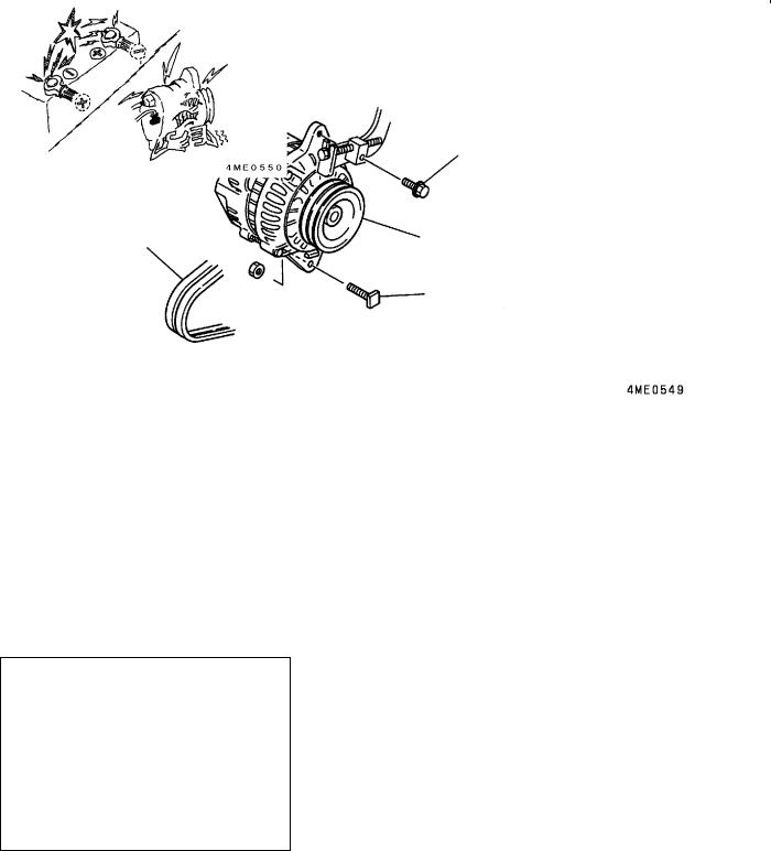
3. GENERATOR ASSEMBLY
REMOVAL AND INSTALLATION
1
2
4 |
5 |
3
Removal steps
1.Wiring harness
2.Adjusting bolt
3.Bolt
4.V-belt (Refer to page 11B-5-1.)
"AA 5. Generator
REMOVAL SERVICE POINT
"AAGENERATOR INSPECTION
Caution in Handling Generator
The following caution should be taken when servicing the generator 5.
Be sure to connect the generator 5 to the battery correctly. Reversed polarity causes an excessive current to flow from the battery to the generator 5, damaging the diodes and voltage regulator.
E Mitsubishi Motors Corporation |
Feb. 2000 |
PWEE9409-D |
Added |

4M41 ENGINE - Glow Plug |
11B-4-1 |
|
|
4. GLOW PLUG
REMOVAL AND INSTALLATION
13 ± 1 Nm
18 ± 1 Nm
1
4
5
Removal steps
1.Nut
2.Glow plug wiring harness
3.Connection plate
4.Glow plug
3
7
2
6
5.Coolant temperature sensor (For engine control)
6.Glow relay
7.Engine ECU
INSPECTION
GLOW PLUG
Measure resistance of the glow plug 4. Replace the glow plug if the reading deviates from the specified standard value.
Standard value: 1.1 W
E Mitsubishi Motors Corporation |
Feb. 2000 |
PWEE9409-D |
Added |
4M41 ENGINE - Cooling Fan, V-belt and Water Pump |
11B-5-1 |
|
|
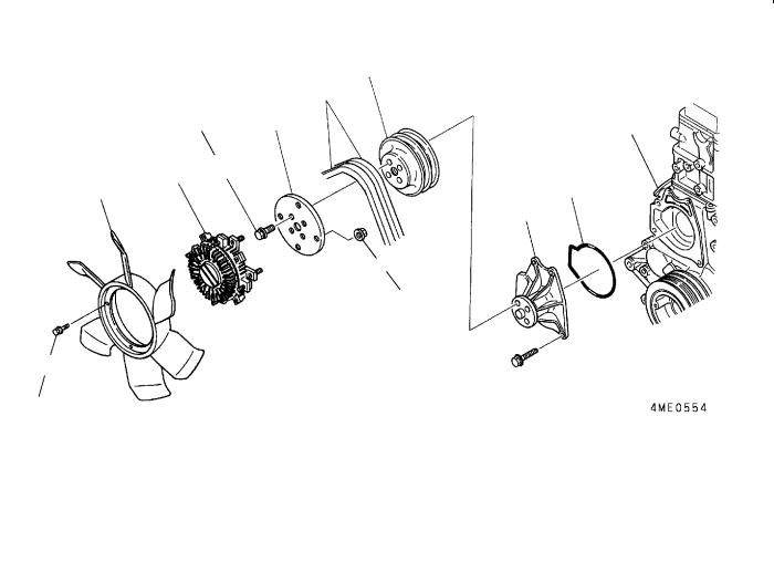
5. COOLING FAN, V-BELT AND WATER PUMP
REMOVAL AND INSTALLATION
|
|
|
|
8 |
|
|
|
|
5 |
|
|
7 |
*1 |
|
|
24 ± 2 Nm |
|||
|
|
|
|
|
4 |
6 |
|
|
|
2 |
|
|
|
10 |
|
|
|
|
9 |
3
24 ± 2 Nm
1
10 ± 1 Nm
Removal steps
1.Bolt
2.Cooling fan
3.Nut
4.Auto-cooling fan coupling
5.V-belt
6.Bolt
7.Coupling plate
8.Water pump pulley
9.Water pump assembly
10.O-ring
*1: Timing gear case
E Mitsubishi Motors Corporation |
Feb. 2000 |
PWEE9409-D |
Added |
11B-5-2 4M41 ENGINE - Cooling Fan, V-belt and Water Pump
5
A
C B
B
A
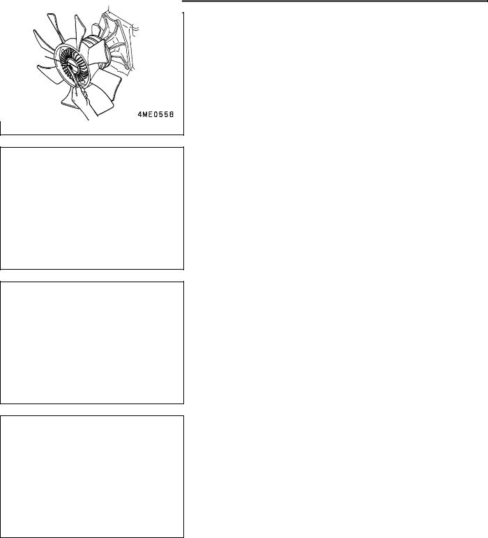
INSPECTION
1. AUTO-COOLING FAN COUPLING
Check the auto-cooling fan coupling 4, and replace if any of the following conditions exists:
(1)Hydraulic fluid is leaking from the hermetically sealed housing.
(2)The coupling turns irregularly or produces an abnormal sound when rotated by hand due to defective inside bearing.
(3)The coupling has an excessive axial play when moved with the engine in a cold state.
2.V-BELT
(1)Push the V-belt 5 at its midpoint with a force of approximately 98 N as shown and read the amount of deflection A.
(2)If the reading deviates from the specified standard value, accomplish the following adjustment.
(3)Loosen the bolt and nut B holding the generator, and adjust the tension of the V-belt 5 using the adjusting bolt C.
Caution
1.Be sure to retighten the bolt and nut securely after the adjustment.
2.Excessive tension damages not only the V-belt 5 itself but bearings elsewhere.
3.Be sure to replace the V-belt 5, when necessary, in pairs and keep it slush-free.
CLEANING
Remove foreign matters, if any, from the bimetal A using care not to apply unnecessary force to it.
E Mitsubishi Motors Corporation |
Feb. 2000 |
PWEE9409-D |
Added |

4M41 ENGINE - Water Hoses and Pipes |
11B-6-1 |
|
|
6. WATER HOSES AND PIPES
REMOVAL AND INSTALLATION
25 ± 2 Nm
"AA
3
4


8


6 7
9 ± 1 Nm
2 |
|
5 |
||
|
|
1 |
|
|
|
|
25 ± 2 Nm |
||
|
25 ± 2 Nm |
|||
|
|
|||
|
|
|
|
|
Removal steps
1.Turbocharger water outlet pipe
2.Turbocharger water inlet pipe
3.Heater return pipe
4.O-ring
5.Harness
6.Coolant temperature sensor (For water temperature gauge)
7.Water outlet pipe
8.Gasket
E Mitsubishi Motors Corporation |
Feb. 2000 |
PWEE9409-D |
Added |
11B-6-2 |
4M41 ENGINE - Water Hoses and Pipes |
|
|
INSTALLATION SERVICE POINTS
"AAO-RING INSTALLATION
Caution
Engine oil swells O-rings. When installing the O-rings 4, be sure that they are free of engine oil.
E Mitsubishi Motors Corporation |
Feb. 2000 |
PWEE9409-D |
Added |
4M41 ENGINE - Thermostat |
11B-7-1 |
|
|
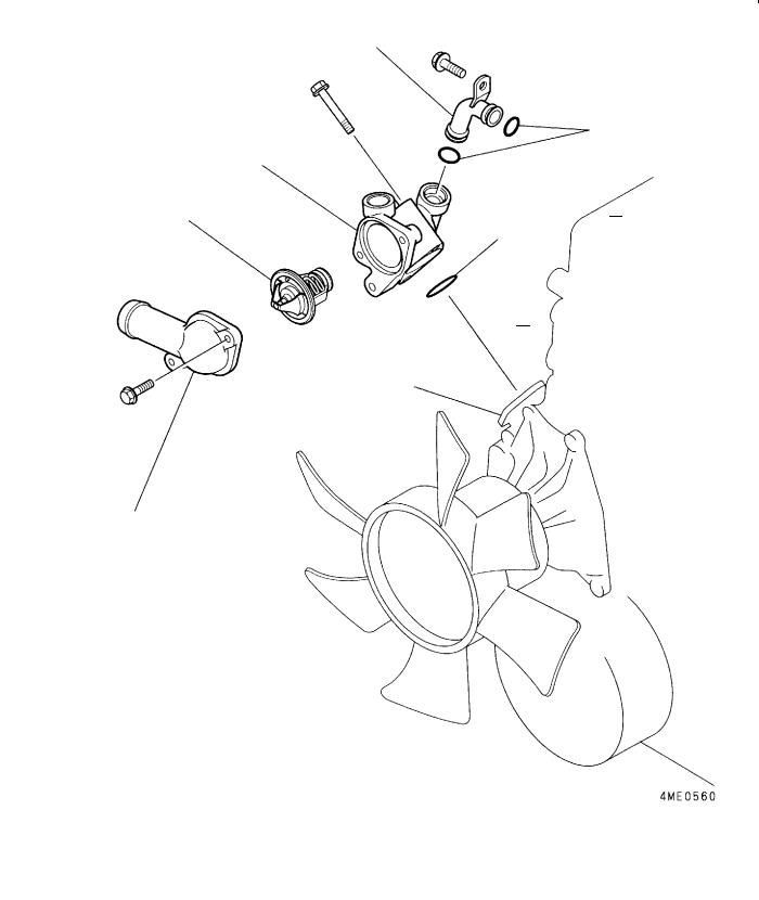
7. THERMOSTAT
REMOVAL AND INSTALLATION
3
4 
5
2
6 


1
Removal steps
1. Thermostat cover
"BA 2. Thermostat 3. Bypass pipe
"AA 4. O-ring
5. Thermostat case "AA 6. O-ring
E Mitsubishi Motors Corporation |
Feb. 2000 |
PWEE9409-D |
Added |
11B-7-2 4M41 ENGINE - Thermostat
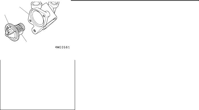
INSTALLATION SERVICE POINTS
"AAO-RING INSTALLATION
Caution
Engine oil swells O-rings. When installing the O-rings 4 and 6, be sure that they are free of engine oil.
|
|
"BATHERMOSTAT INSTALLATION |
|
5 |
|
|
Install the thermostat 2 with its jiggle valve A located at the |
|
|
|
|
A |
|
uppermost position. |
2
E Mitsubishi Motors Corporation |
Feb. 2000 |
PWEE9409-D |
Added |
4M41 ENGINE - EGR Valve Assembly |
11B-8-1 |
|
|
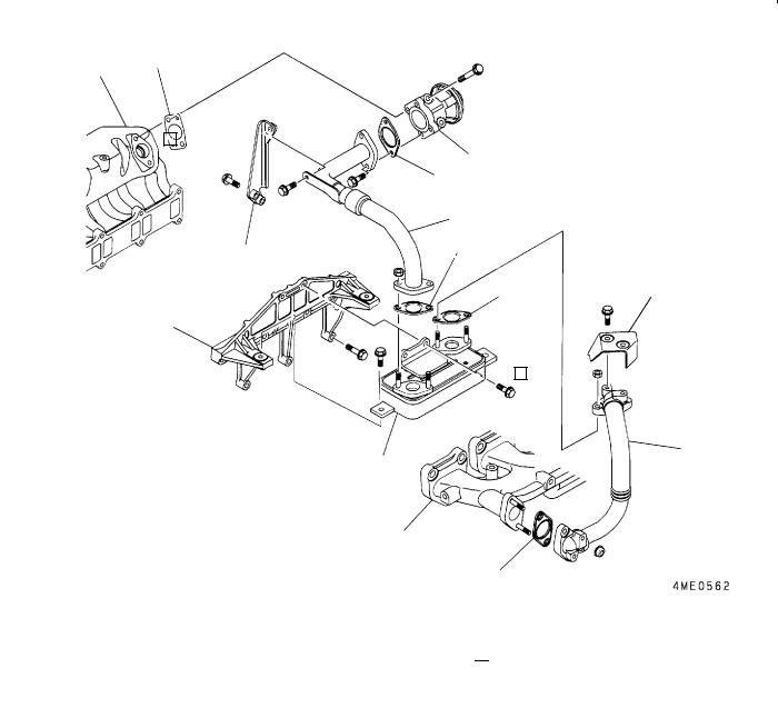
8. EGR VALVE ASSEMBLY
REMOVAL AND INSTALLATION
*a |
5 |
|
|
||
|
|
3
10
Removal steps
1.EGR pipe
2.Gasket
3.EGR pipe stay
4.EGR valve
5.Gasket
6.Insulator
7.EGR pipe
4
2


1
2


8 |
|
6 |
|
7
9
*b


 8
8
8.Gasket
9.EGR box
10.EGR box bracket
*a: Intake manifold *b: Exhaust manifold
E Mitsubishi Motors Corporation |
Feb. 2000 |
PWEE9409-D |
Added |
4M41 ENGINE - Intake Manifold |
11B-9-1 |
|
|
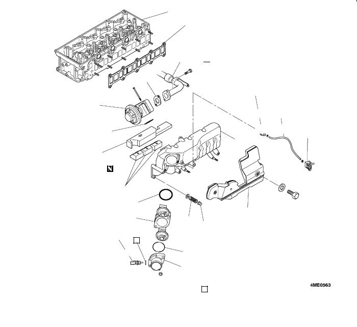
9. INTAKE MANIFOLD
REMOVAL AND INSTALLATION
*b
18 


*a
3 


17 ± 1 Nm
2
12 11
3 |
10 |
|
16
13
17
|
9 |
|
1 |
|
|
|
|||
8 |
15 |
|||
14 |
||||
|
|
|||
15 ± 1 Nm 5
4 |
7 |
|
|
||
|
||
|
6 |
|
Removal steps |
|
|
|
1. |
Side cover |
12. |
Gas filter assembly |
2. |
EGR valve |
13. |
Rubber spacer A |
3. |
Gasket |
14. |
Nut |
4. |
Boost air temperature sensor |
15. |
Spring |
5. |
Gasket |
16. |
Intake manifold |
6. |
Air inlet fitting |
17. |
Rubber spacer B |
7. |
O-ring |
"AA 18. |
Gasket |
8. |
Throttle body assembly |
|
|
9. |
O-ring |
*a. EGR pipe |
|
10. |
Boost pressure sensor |
*b. Cylinder head |
|
11. |
Boost hose |
|
|
E Mitsubishi Motors Corporation |
Feb. 2000 |
PWEE9409-D |
Added |

11B-9-2 |
4M41 ENGINE - Intake Manifold |
|
|
Cylinder head
Gasket
Gasket
Cylinder head
INSTALLATION SERVICE POINT
"AAGASKET INSTALLATION
Fit the gasket to the cylinder head in the direction shown in the illustration.
E Mitsubishi Motors Corporation |
Feb. 2000 |
PWEE9409-D |
Added |

4M41 ENGINE - Turbocharger Assembly |
11B-10-1 |
|
|
10. TURBOCHARGER ASSEMBLY
REMOVAL AND INSTALLATION
11
*2
25 ± 2 Nm
*3
14
54 ± 5 Nm
10 |
*1 |
|
5 |
|
20 Nm |
49 ± 4 Nm |
|
|
|
2 |
1 |
4 |
|
||
|
|
13
6
|
|
8 |
7 |
||
|
|
|
|
||
|
|
|
|
|
|
|
|
|
|
|
|
3 |
9 |
|
12 |
|
|
|
|
|
|
|
|
49 |
± 4 Nm |
|
|
|
|
||
|
|
|
|
|
Removal steps |
|
|
|
1. |
Eyebolt |
11. |
Insulator B |
2. |
Oil feed pipe |
12. |
Insulator A |
3. |
Oil return pipe |
13. |
Gasket |
4. |
Nut |
"AA 14. |
Turbocharger assembly |
5. |
Coupler insulator |
|
|
6. |
Insulator |
*1: Exhaust manifold |
|
7. |
Coupler |
*2: Turbocharger water outlet pipe |
|
8. |
Gasket |
|
(Refer to page 11B-6-1.) |
9. |
Nut |
*3: Turbocharger water inlet pipe |
|
10. |
Bolt |
|
(Refer to page 11B-6-1.) |
E Mitsubishi Motors Corporation |
Feb. 2000 |
PWEE9409-D |
Added |
11B-10-2 |
4M41 ENGINE - Turbocharger Assembly |
|
|
A
C
B
INSTALLATION SERVICE POINT
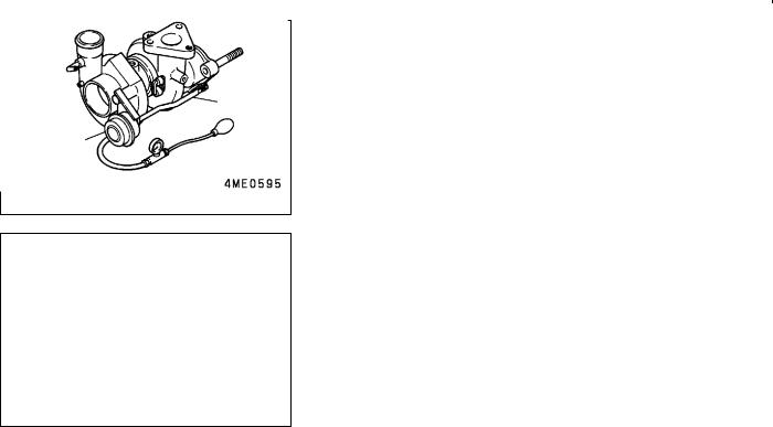
"AATURBOCHARGER ASSEMBLY INSTALLATION
(1)Prior to installing the turbocharger assembly 14, pour engine oil into it through the oil inlet hole A to lubricate its component parts for smooth movement.
(2)Using a tester, apply pressure to the actuator B and read the pressure at which the rod C begins to move (approximately 1 mm).
If the reading deviates from the specified standard value, replace the actuator.
Standard value: 161 kPa
Caution
Do not load the actuator B with any more pressure than 181 kPa nor carry the turbocharger by holding the rod C, or the diaphragm may be damaged.
E Mitsubishi Motors Corporation |
Feb. 2000 |
PWEE9409-D |
Added |

4M41 ENGINE - Exhaust Manifold |
11B-11-1 |
|
|
11. EXHAUST MANIFOLD
REMOVAL AND INSTALLATION
*1 |
3 |
2 |
6
1 |
7 |
|
|
||
|
*2
5
30 ± 3 Nm
*3
49 ± 4 Nm |
4 |
|
Removal steps |
|
|
1. |
Insulator |
*1: EGR pipe |
2. |
Insulator |
*2: Cylinder head |
3. |
Bolt |
*3: Turbocharger |
4.Nut
5.Nut
6.Exhaust manifold
7.Gasket
E Mitsubishi Motors Corporation |
Feb. 2000 |
PWEE9409-D |
Added |
|
4M41 ENGINE - Injection Pump Assembly |
|
|
|
11B-12-1 |
||||||
|
|
|
|
|
|
|
|
|
|||
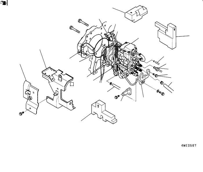
12. INJECTION PUMP ASSEMBLY |
|
|
|
|
|
|
|
||||
REMOVAL AND INSTALLATION |
|
|
|
|
|
|
|
|
|||
|
|
|
|
4 |
|
|
|
|
|
|
|
|
|
|
|
6 |
|
|
|
|
|
|
|
|
|
|
|
7 |
|
|
|
|
|
|
|
|
|
|
|
5 |
|
|
|
|
|
|
|
|
|
|
|
17 |
19 |
||||||
|
2 |
|
|
|
|
|
|
|
|
|
|
|
20 |
|
|
|
11 |
|
|
|
|
|
|
1 |
|
18 |
|
13 |
|
|
|
||||
|
|
||||||||||
|
|
|
|
|
|
|
|
|
|
|
|
|
|
|
|
|
|
25 ± 2 Nm |
|||||
|
|
|
|
|
|
|
|
|
|
|
|
|
|
|
|
|
14 |
|
|
|
|||
|
|
9 |
8 |
|
|
18 ± 2 Nm |
|
||||
|
|
|
|
12 |
|
|
|
||||
|
|
|
|
|
|
|
|
||||
|
|
|
|
10 |
|
|
|
|
|
|
|
|
|
|
|
|
|
|
|
|
|
|
|
15
16
3
Removal steps |
|
|
|
1. |
Injection pump cover B |
11. |
Fuel leak-off hose |
2. |
Injection pump cover A |
12. |
Fuel suction hose |
3. |
Rubber spacer |
AA" "BA 13. |
Injection pipe |
4. |
Rubber spacer |
14. |
Bolt |
5. |
Harness |
15. |
Pump stay |
6. |
Harness |
16. |
Pump stay |
7. |
Harness |
"AA 17. |
Injection pump assembly |
8. |
Harness |
18. |
O-ring |
9. |
Harness |
19. |
Rubber spacer |
10. |
Fuel return hose |
20. |
Stay |
Caution
1.Fuel is highly flammable. Keep it away from flames and sources of heat.
2.Be sure to wipe up spilt fuel completely. It could catch fire.
3.Have the injection pump assembly 17 serviced at an appropriate Zexel service station.
4.Dust particles entering the injection pump assembly 17 can seriously affect the engine performance. To prevent it, fully cover the openings left after the removal of parts such as pipes and hoses.
5.Before installing the injection pipe 13, check to ensure that the pipe seating surface is free from any damage and unevenness.
E Mitsubishi Motors Corporation |
Feb. 2000 |
PWEE9409-D |
Added |
Loading...